
Copyright © 2001 American Industrial Heat Transfer, Inc.
Shell & Tube Heat Exchangers Air Cooled Heat Exchangers
Visit our web site at
www.aihti.com
®
INSTALLATION & MAINTENANCE MANUAL
2001
Shell & tube cut-away and standard features ...................Page 2
Shell & tube installation & maintenance instructions ......Page 3
Shell & tube maintenance & schematic ...........................Page 4
Shell & tube piping diagram ............................................Page 5
Shell & tube accessories ..................................................Page 6
Air cooler general installation and maintenance ..............Page 7-8
Table of Contents
AOCS piping hook-up ................................Page 9
AC, AOCH, EOC, ACA piping hook-up ....Page 10
AOM, BM, LP, AOMF piping hook-up ......Page 11
Air cooler accessories ................................Page 12
Terms and conditions of sale ......................Page 13-15
Available products ......................................Page 16

Copyright © 2001 American Industrial Heat Transfer, Inc.
1- MOUNTING BRACKET
Heavy gauge steel mounting brackets are adjustable in
orientations to 360 degrees.
2- BONNET
Provides fluid into tubes with minimum restriction. One,
two, or four pass interchangeability.
3- FLOW CAVITY
Generously sized to allow for minimum pressure drop
and more uniform flow.
4- TUBES JOINT
Roller expanded tube joint to integral forged hub.
5- TUBES SHEET
Precision-machined tube-sheet provides for long last-
ing high strenght service.
6- THREAD
CNC precision threading to provide accurate leakproof
connections.
7- BAFFLES
CNC manufactured baffles to provide maximum turbu-
lence and heat transfer with a minimum fluid pressure
drop.
8- FINISH
Gray semigloss enamel suitable for outdoor service.
Can be used as a base for additional coats.
9- SHELL & TUBE BUNDLE ASSEMBLY
CNC precision manufactured parts to guarantee a close
fit between the baffles, tubes, and shell. Clearances are
minimized to provide for maximum heat transfer.
10- HUB
Premium quality forging with full opening designed
for minimum pressure drop.
11- FULL FACE GASKET
Full-face composite gasket for maximum pressure
and temperature.
12- DRAIN PORT
Drain ports allow for easy draining of tube side.
Optional zinc anode can be inserted in place of plug.
Note: Standard Feature descriptions are qualified by
and subject to product specifications which are avail-
able from American Industrial upon request.
1
2
3
4
6
7
8
9
10
11
12
1
2
3
4
6
7
9
10
11
12
8
1
2
3
4
6 7
8
9
11
12
AB , AB-2000, SAE, STS & EAB
SERIES
AA , STA & FBF
SERIES
CS , STC & CK
SERIES
SHELL & TUBE HEAT EXCHANGERS STANDARD FEATURES
5
2

Copyright © 2001 American Industrial Heat Transfer, Inc.
SHELL & TUBE GENERAL INSTALLATION & MAINTENANCE
Receiving
a) Inspect unit for any shipping damage before uncrating. Indicate
all damages to the trucking firms' delivery person, and mark it on
the receiving bill before accepting the freight. Make sure that there
is no visible damage to the outside surface of the heat exchanger.
Since the warranty is based upon the unit date code located on the
model identification tag, removal or manipulation of the identifi-
cation tag will void the manufacturers warranty.
b) When handling the shell & tube heat exchanger, special care
should be taken to avoid dropping the unit since mishandling could
cause the heat exchanger to crack and leak externally. Mishandling
of the unit is not covered under the manufacturers warranty. All
units are shipped with partial wood/corrugated cardboard contain-
ers for safe handling.
c) Standard Enamel Coating: American Industrial provides its stan-
dard products with a normal base coat of oil base air cure enamel
paint. The enamel paint is applied as a temporary protective and
esthetic coating prior to shipment. While the standard enamel coat-
ing is durable, American Industrial does not warranty it as a long-
term finish coating. It is strongly suggested that a more durable
final coating be applied after installation or prior to long-term stor-
age in a corrosive environment to cover any accidental scratches,
enhance esthetics, and further prevent corrosion. It is the responsi-
bility of the customer to provide regular maintenance against chips,
scratches, etc... and regular touch up maintenance must be pro-
vided for long-term benefits and corrosion prevention.
d) Special Coatings: American Industrial offers as customer op-
tions, Air-Dry Epoxy, and Heresite (Air-Dry Phenolic) coatings at
additional cost. American Industrial offers special coatings upon
request, however American Industrial does not warrantee coatings
to be a permanent solution for any equipment against corrosion. It
is the responsibility of the customer to provide regular maintenance
against chips, scratches, etc... and regular touch up maintenance
must be provided for long-term benefits and corrosion prevention.
Installation
a) American Industrial recommends that the equipment supplied
should be installed by qualified personnel who have solid under-
standing of system design, pressure and temperature ratings, and
piping assembly. Verify the service conditions of the system prior
to applying any shell & tube heat exchanger. If the system pressure
or temperature does not fall within the parameters on model rating
tag located on the heat exchanger, contact our factory prior to in-
stallation or operation.
b) Plan the installation to meet the requirements indicated on the
piping installation diagram as illustrated (page 4). It is recommended
to put the hot fluid to be cooled through the shell side and the cold
fluid through the tube side. The indicated port assembly sequence
in the diagram maximizes the performance, and minimizes the pos-
sibility of thermal shock. In instances where the fluids are required
to be reversed, hot fluid in the tubes and cold fluid in the shell the
heat exchanger will work with reduced performance.
c) When installing a series EAB heat exchanger (expansion bel-
low), it is recommended to use a shoulder bolt to allow the heat
exchanger to move freely while expanding and contracting due to
high differential temperatures.
d) It is recommended to use flexible hose wherever possible to
reduce vibration and allow slight movement. However, hoses are
not required. Hydraulic carrying lines should be sized to handle
the appropriate flow and to meet system pressure drop require-
ments based upon the systems parameters, and not based upon the
units supply and return connection size. We recommend that a low
cracking pressure direct acting relief valve be installed at the heat
exchanger inlet to protect it from pressure spikes by bypassing oil
in the event the system experiences a high flow surge. If preventa-
tive filtration is used it should be located ahead of the cooler on
both shell and tube side to catch any scale or sludge for the system
before it enters the cooler. Failure to install filters ahead of the heat
exchanger could lead to possible heat exchanger failure due to high
pressure if the system filters plug.
e) Standard shell & tube coolers are built with a rolled tube-sheet
construction. However, the differential operating temperature be-
tween the entering shell side fluid and the entering tube side fluid
should not exceed 150°F. If this condition exists, a severe thermal
shock could occur leading to product failure and mixing of the
fluids. For applications with a differential temperatures of 150°F
or more, we recommend using a series with a floating tube-sheet,
u-tube, or expansion joint to reduce the potential for the effects of
thermal shock.
g) Water requirements vary from location to location. If the source
of cooling water is from other than a municipal water supply, it is
recommended that a water strainer be installed ahead of the heat
exchanger to prevent dirt and debris from entering and clogging
the flow passages. If a water modulating valve is used it is recom-
mended to be installed at the inlet to the cooler to regulate the
water flow.
h) For steam service, or other related applications, please consult
our engineering department for additional information.
Maintenance
a) Inspect the heat exchanger for loosened bolts, connections, rust
spots, corrosion, and for internal or external fluid leakage. Any
corroded surfaces should be cleaned and recoated with paint.
b) Shell side: In many cases with clean hydraulic system oils it will
not be necessary to flush the interior of the shell side of the cooler.
In circumstances where the quality of hydraulic fluid is in ques-
tion, the shell side should be disconnected and flushed on a yearly
basis with a clean flushing oil/solvent to remove any sludge that
has been deposited. For severe cases where the unit is plugged and
cannot be flushed clean with solvent, the heat exchanger should be
replaced to maintain the proper cooling performance.
c) Tube side: In many cases it will be necessary to clean the tube
side of the heat exchanger due to poor fluid quality, debris, cal-
cium deposits, corrosion, mud, sludge, seaweed, etc.... To clean
3

Copyright © 2001 American Industrial Heat Transfer, Inc.
the tube side, flush with clean water or any good quality commer-
cial cleaner that does not attack the particular material of construc-
tion. With straight tube heat exchangers you can use a rod to care-
fully push any debris out of the tubes.
d) Zinc anodes are normally used to reduce the risk of failure due
to electrolysis. Zinc anodes are a sacrificial component designed
to wear and dissolve through normal use. Normally, zinc anodes
are applied to the water supply side of the heat exchanger. Depend-
ing upon the amount of corrosive action, one, two, three, or more
anodes can be applied to help further reduce the risk of failure.
American Industrial Heat Transfer, Inc. offers zinc anodes as an
option, to be specified and installed at the request our customers. It
is the responsibility of the customer to periodically check and verify
the condition of the zinc anode and replace it as needed.
Applications vary due to water chemical makeup and quality, ma-
terial differences, temperature, flow rate, piping arrangements, and
machine grounding. For those reasons, zinc anodes do not follow
any scheduled factory predetermined maintenance plan moreover
they must be checked routinely by the customer, and a mainte-
nance plan developed based upon the actual wear rate.
If substantial wear occurs or zinc dissolves without replacement,
premature failure or permanent damage may occur to the heat ex-
changer. American Industrial does not warranty customer applica-
tions. It is the responsibility of the customer to verify and apply the
proper system materials of construction and overall system require-
ments. Failures resulting from properly applied or misapplied use
of zinc anode(s) into non-specified or specified applications will
be the sole responsibility of the customer.
e) A routine maintenance schedule should be developed and ad-
justed to meet your systems requirements based upon water qual-
ity, etc….Failure to regularly maintain and clean your heat ex-
changer can result in a reduction in operational performance and
life expectancy.
SHELL & TUBE GENERAL INSTALLATION & MAINTENANCE
3/8" NPT Thread
1.84"
1.00"
0.86"
0.50"ø
0.75"
1/2" NPT Thread
2.70"
1.15"
0.63"ø
1.00" 1.75"
3/8" NPT Zinc Anode
PN: 301-0004
AB-400 thru AB-1000
AA-400 thru AA-1000
CS-600 thru CS-1000
1/2" NPT Zinc Anode
PN: 301-0003
AB-1200 thru AB-2000
AA-1200 thru AA-1600
CS-1200 thru CS-1700
Return Line
Relief Valve
Return Line
Filter
Heat
Exchanger
Y Strainer
Water Modulating Valve
To Tower
Or Drain
TUBE SIDE PASSES
The number of passes (SP,TP &FP) refers to the number of runs
back and forth of the cooling fluid on the tube side of the heat
exchanger. Tube passes are normally determined by the rate (gpm)
of water available to be used for cooling purposes (see table E).
The purpose of multi-passes are to increase turbulence by increas-
ing the velocity. Normally tube side passes will not affect pricing.
TABLE E- Flow Rate for Tube Side
Shell Liquid Flow - Tube Side
dia . SP TP FP
Code Min. Max. Min. Max. Min. Max.
400 3.5 21 –– –– –– ––
600 7.5 48 3.5 24 2 12
700 9 61 4.5 30 2.2 15
800 10 50 4.5 38 3 21
1000 20 120 10 70 5.0 37
1200 30 250 15 112 7.5 56
1600 57 460 29 180 14 90
1700 57 300 29 180 14 90
2000 90 650 45 320 25 160
TYPICAL HYDRAULIC CIRCUIT
with water cooled heat exchanger
4

Copyright © 2001 American Industrial Heat Transfer, Inc.
SHELL & TUBE PIPING HOOK-UP
URCSR Series
UCSR Series
Vent Port
Condensate out
Steam In
Fluid Out
Fluid In
Mounting
Air Out
Water In
Water Out
Drain Port
Air In
Mounting
(Both Sides)
C
B
B
B
A
A
A
D
D
D
C
C
C
B
B
B
A
A
A
D
D
C
D
C
ONE PASS TWO PASS FOUR PASS
A .......... Hot fluid to be cooled
B ......................... Cooled fluid
C .................. Cooling water in
D ................ Cooling water out
SP ......................... Single Pass
TP .............................Two Pass
FP ............................ Four Pass
AB Series
SAE Series
EAB Series
STS Series
SRAB Series
UAB Series
URAB Series
AA Series
STA Series
CS Series
STC Series
CK Series
SRCS Series
URCS Series
ONE PASS TWO PASS FOUR PASS
ABR Series
5

Copyright © 2001 American Industrial Heat Transfer, Inc.
SHELL & TUBE ACCESSORIES
APPLICATIONS & SPECS. ("Y" Strainers)
These strainers are engineered for water or steam, and are adaptable for many other uses. Cleaning is accomplished by simply removing a pipe
plug without disconnecting any piping. Or, if it is desirable to clean without interrupting service, a blow-off valve can be connected to the
clean-out opening. Note: Pumps, control valves, traps, or other equipment controlling the flow of liquids or gases require proper protection
with strainers for trouble free operation.
18 - Y BRASS STRAINERS
The 18 - Y strainer body is a red brass casting. Standard units have 50 mesh brass wire screens. Brazing connections are available on special
order instead of pipe threads.
20 - Y STRAINERS
The 20 - Y strainer has a heavy cast iron body with machined pipe thread inlet and outlet (National Pipe Thread N.P.T.). It contains a strainer
screen of 0.02" thick brass with 100, 1/16" perforations per inch.
C
D
A
Pipe Thread
INLET
OUTLET
E
Clean-out
Opening
Pipe Threa
d
B
MODEL
SIZE
A
(NPT)
DIMENSIONS (Inches)
WT.
(lbs.)
BCD
E
(NPT)
18 - Y
0.38"
0.50"
0.75"
1.00"
2.50"
2.50"
3.50"
3.50"
2.63"
2.63"
3.75"
3.75"
2.00"
2.00"
2.75"
2.75"
0.25"
0.25"
0.50"
0.50"
0.75
0.75
1.75
1.75
20 - Y
0.50"
0.75"
1.00"
1.25"
1.50"
2.00"
4.00"
4.00"
4.75"
6.00"
6.00"
8.13"
3.25"
3.25"
4.38"
5.13"
5.13"
6.38"
2.50"
2.50"
3.38"
3.88"
3.88"
4.63"
0.38"
0.38"
0.75"
0.75"
0.75"
0.75"
1.75
1.75
4.00
4.75
4.75
13.00
PRESSURE RATINGS, ALL MODELS: 125lbs. per Sq.In.
"Y" STRAINER (for Shell & Tube Heat Exchangers And Air/Oil Coolers)
THERMOSTATIC MODULATING WATER VALVE WITH BULB WELL ASSEMBLY
(for Shell & Tube Heat Exchangers And Air/Oil Coolers)
SPECIFICATIONS
Sizes 0.375", 0.50", 0.75", 1.00", 1.25" FPT
Fluid Pressure 125psi (max.)
Standard Temperature 40° - 100° F., 60° - 140° F., 100° - 175° F., 125° - 200° F.,
140° - 240° F., 200° - 275°F.
Body Brass alloy casting
Valve Parts Brass alloy
Standard Capillary Length 6’ & 20’ foot
Standard Bulbs For 3/8" & 1/2" valve sizes: 5/8" x 6 with 3/4" union
connections. For 3/4" & 1" valve sizes: 5/8" x 8-1/4"
with 3/4" union connections.
Stainless steel construction available.
Standard Bulb Mounting 3/4" NPT
Seat Disk Buna-N-replaceable
Seat Bead Stainless Steel - replaceable
Water Valve
Durable Bronze
Two-ply Bellows
(inside)
Armor-plated
Double Braided
Copper Capillary
Body and
Valve Parts
Are Special
Brass Alloy
Adjusting Cap
For Better
Temperature
Control
Copper
Alloy Bulb
APPLICATION INFORMATION
• Built for machine tool and hydraulic applications.
• Adjustable temperature range.
• Response to temperature changes.
• Direct acting bellows for longer service.
Note: Please consult factory if a non-cataloged temperature is required.
The type 56-T valve gives smooth regulation of water and other fluids. It's designed for rugged application. For example: hydraulic power
packaging equipment, hydraulic presses, plastic molding equipment, and anywhere reliability in temperature control is demanded.
The type 56-T valve is a better designed product that won't leak or chatter. For dependability, every valve is factory tested three times in
different temperature baths. They are direct acting with sturdy walls, and the inner spring is zinc coated. The seat beads are stainless steel to
resist the erosive effects of wire drawing and provide durability for your needs. Additional features include mounting in any position, Buna-
N seat disc, and manual flushing.
6

Copyright © 2001 American Industrial Heat Transfer, Inc.
AIR COOLED GENERAL INSTALLATION & MAINTENANCE
Receiving:
a) Inspect unit for any shipping damage before uncrating. Indicate
all damages to the trucking firms' delivery person and mark it on
the receiving bill before accepting the freight. Make sure that the
core and fan are not damaged. Rotate the fan blade to make sure
that it moves freely. Since the warranty is based upon the unit date
code located on the model identification tag, removal or manipu-
lation of the identification tag will void the manufacturers war-
ranty.
b) When handling the heat exchanger, special care should be taken
to avoid damage to the core and fan. All units are shipped with
wood skids for easy forklift handling
c) Standard Enamel Coating: American Industrial provides its stan-
dard products with a normal base coat of oil base air cure enamel
paint. The enamel paint is applied as a temporary protective and
esthetic coating prior to shipment. While the standard enamel coat-
ing is durable, American Industrial does not warranty it as a long-
term finish coating. It is strongly suggested that a more durable
final coating be applied after installation or prior to long-term stor-
age in a corrosive environment to cover any accidental scratches,
enhance esthetics, and further prevent corrosion. It is the responsi-
bility of the customer to provide regular maintenance against chips,
scratches, etc... and regular touch up maintenance must be pro-
vided for long-term benefits and corrosion prevention.
d) Special Coatings: American Industrial offers as customer op-
tions, Air-Dry Epoxy, and Heresite (Air-Dry Phenolic) coatings at
additional cost. American Industrial offers special coatings upon
request, however American Industrial does not warranty coatings
to be a permanent solution for any equipment against corrosion. It
is the responsibility of the customer to provide regular maintenance
against chips, scratches, etc... and regular touch up maintenance
must be provided for long-term benefits and corrosion prevention.
Installation:
a) American Industrial recommends that the equipment supplied
should be installed by qualified personnel who have solid under-
standing of system design, pressure and temperature ratings, and
piping assembly. Verify the service conditions of the system prior
to applying any air cooled heat exchanger series cooler. If the sys-
tem pressure or temperature does not fall within the parameters on
model rating tag located on the heat exchanger, contact our factory
prior to installation or operation.
b) In order for the heat exchanger to properly function, installation
should be made with minimum airflow obstruction distance of not
less than twenty (20) inches on both fan intake and exiting side of
the heat exchanger.
c) Process piping should beinstalled as indicated on the model dia-
gram, with the process flow entering into the INLET port and exit-
ing out the OUTLET port (see illustrations pages 9-10). Flexible
hose or non rigid plumbing can be used to reduce the risk of failure
due to thermal expansion of the core or hydraulic vibration. We
suggest that preventative filtration should be located ahead of the
cooler to catch any scale or sludge for the system before it enters
the cooler.
For hydraulic oil coolers is it suggested that a three-way thermal
bypass valve or a direct acting low-pressure (30psi or 60psi) relief
valve be installed at the inlet to the cooler to protect it in cold weather
environments.
d) Flow line sizes should be sized to handle the appropriate flow to
meet the system pressure drop requirements. If the nozzle size of
the heat exchanger is smaller than the process line size an increased
pressure differential at the heat exchanger may occur.
e) A brazed construction coil does not allow internal tube access. A
serviceable core
®
will allow full accessibility to the internal tubes
for cleaning and maintenance.
g) Electric motors should be connected only to supply source of
the same characteristics as indicated on the electric motor infor-
mation plate. Prior to starting, verify that the motor and fan spin
freely without obstruction. Check carefully that the fan turns in the
correct rotation direction (normally counter clockwise) from the
motor side (fan direction arrow). Failure to operate the fan in the
proper direction could reduce performance or cause serious dam-
age to the heat exchanger or other components. Fan blades should
be rechecked for tightness after the first 100 hours of operation.
h) It is important to apply the catalog recommended flow rate for
the hydraulic motor that corresponds with the specific model be-
ing used. A case drain is required for hydraulic motor installation.
Failure to connect case drain can result in motor failure. The proper
flow rate and direction to the hydraulic motor are critical to ensure
fan direction and RPM. Exceeding the recommended RPM could
result in fan failure and cause severe damage to the heat exchanger.
See fan rotation (pages 9-10)
Maintenance
Regular maintenance intervals based upon the surrounding and op-
erational conditions should be maintained to verify equipment per-
formance and to prevent premature component failure. Since some
of the components such as, motors, fans, load adapters, etc... are
not manufactured by American Industrial, maintenance require-
ments provided by the manufacture must be followed.
a) Inspect the entire heat exchanger and motor/fan assembly for
loosened bolts, loose connections, broken components, rust spots,
corrosion, fin/coil clogging, or external leakage. Make immediate
repairs to all affected areas prior to restarting and operating the
heat exchanger or its components.
b) Heat exchangers operating in oily or dusty environments will
often need to have the coil cooling fins cleaned. Oily or clogged
fins should be cleaned by carefully brushing the fins and tubes
with water or a non-aggressive degreasing agent mixture (Note:
Cleaning agents that are not compatible with copper, brass, alumi-
num, steel or stainless steel should not be used). A compressed air
or a water stream can be used to dislodge dirt and clean the coil
further. Any external dirt or oil on the electric motor and fan as-
sembly should be removed. Caution: Be sure to disconnect the
electric motor from its power source prior to doing any mainte-
nance.
c) In most cases it is not necessary to internally flush the coil. In
circumstances where the coil has become plugged or has a sub-
stantial buildup of material, flushing the coil with water or a sol-
vent may be done. Flushing solvents should be non-aggressive suit-
7

Copyright © 2001 American Industrial Heat Transfer, Inc.
AIR COOLED GENERAL INSTALLATION & MAINTENANCE
able for the materials of construction. Serviceable Core® models
can be disassembled and inspected or cleaned if required.
d) Most low horsepower electric motors do not require any addi-
tional lubrication. However, larger motors must be lubricated with
good quality grease as specified by the manufacture at least once
every 6-9 months or as directed by the manufacture. T.E.F.C. air
ventilation slots should be inspected and cleaned regularly to pre-
vent clogging and starving the motor of cooling air. To maintain
the electric motor properly see the manufactures requirements and
specifications.
e) Fan blades should be cleaned and inspected for tightness during
the regular maintenance schedule when handling a fan blade care
must be given to avoid bending or striking any of the blades. Fan
blades are factory balanced and will not operate properly if dam-
aged or unbalanced. Damaged fan blades can cause excessive vi-
bration and severe damage to the heat exchanger or drive motor.
Replace any damaged fan with an American industrial suggested
replacement.
f) Air cooled exchanger cabinets are constructed using 7ga. through
18ga. steel that may be bent back into position if damaged. Parts
that are not repairable can be purchased through American Indus-
trial.
g) Coil fins that become flattened can be combed back into posi-
tion. This process may require removal of the coil from the cabi-
net.
Brazed Core Maintenance
It is not advisable to attempt repairs to brazed joints of a brazed
construction coil unless it will be done by an expert in silver solder
brazing. Brazed coils are heated uniformly during the original manu-
facturing process to prevent weak zones from occurring. Uncon-
trolled reheating of the coil may result in weakening of the tube
joints surrounding the repair area. In many instances brazed units
that are repaired will not hold up as well to the rigors of the system
as will a new coil. American Industrial will not warranty or be
responsible for any repairs done by unauthorized sources. Manipu-
lation in any way other than normal application will void the manu-
factures warranty.
Serviceable Core
®
Maintenance
Units containing a Serviceable Core
®
have bolted manifold covers
that can be removed for cleaning or repair purposes. Most AOCH
or AOCS cores manufactured after January 1, 1998 are Service-
able Cores
®
.
Servicing Sequence
American Industrial has gone to great lengths to provide compo-
nents that are repairable. If the heat exchanger core requires inter-
nal cleaning or attention the following steps will explain what must
be done to access the internal tubes. Be sure to order gasket kits or
repair parts prior to removal and disassembly to minimize down
time.
a) To clean the internal tubes first remove all connection plumbing
from the unit.
b) Be sure the unit is drained of all water etc...
c) Place the heat exchanger in an area that it can be accessed from
all sides. Remove the core from the cabinet if required (AOCH,
AOCS).
d) Mark the cover
➀ and tube-sheet ➂ for both covers so that
they can be replaced into the same position when finished.
Re-
move the manifold cover bolts
➁
and hardware and place them
into a secure place.
e) The manifold covers are tightly compressed and may need some
prying to separate them from the gasket
≈
, physically remove the
cover assemblies
➀
from both sides.
f) The tubes
√
and turbulators
➄
are now accessible for cleaning.
Note: turbulators are installed on AOCH & AOCS cores only. If
you need to remove the turbulator that runs through the tubing, it
will be necessary to first squeeze the flattened end of the protrud-
ing turbulator
➄
, so that on end will fit through the tube. From the
opposite end pull the turbulator
➄
out. You may need to use pliers
to grip and pull the turbulators
➄
out, especially if there is debris
lodged inside. As the turbulators
➄
come out, most of the dirt will
too, so be prepared. It is suggested that gloves be worn when han-
dling the turbulators
➄
as they may be sharp.
We suggest a mild water-soluble degreaser be used with a brush.
Tubing I.D. is .325 a plastic bristle brush on a rod will work best
for cleaning the tubes
√
. Steel brushes should be avoided since the
steel is harder than the copper tubing and may heavily score the
tubes
√
if used.
g) If there are any leaking tubes
√
you may plug them by carefully
forcing a soft metal plug into the hole and tapping it tight. You may
in some cases weld the leaking tube shut however, care should be
taken since excessive heat may cause surrounding tube joints to
loosen and leak.
h) When finished cleaning or repairing, be sure to replace ALL of
the turbulators
➄
back into any open tubes
√
. When the turbulators
➄
protrude from the opposite end flatten them again so they are
tight and cannot be removed.
i) When finished reattach the manifold covers
➀
in the same posi-
tion they were removed, using new gaskets
≈
, bolts
➁
, and hard-
ware. We suggest using a torque wrench to final tighten the bolts
➁
. For 5/16" bolts 22-23 ft-lbs, for 3/8" bolts to 38-42 ft-lbs. Since
bolts and hardware can physically fatigue during application we
suggest new bolt kits be used when reassembling.
1
2
3
4
6
5
8

Copyright © 2001 American Industrial Heat Transfer, Inc.
UNION
FILTER
UNION
F
a
n
r
o
t
a
t
i
o
n
UNION
FILTER
CAPPED
F
a
n
r
o
t
a
t
i
o
n
AIR COOLED HEAT EXCHANGER PIPING HOOK-UP
AOCS - 1005
through
AOCS - 3015
AOCS - 201
through
AOCS - 603
ONE PASS TWO PASS
ONE PASS TWO PASS
UNION
CAPPED
FILTER
F
a
n
r
o
t
a
t
i
o
n
UNION
FILTER
UNION
F
a
n
r
o
t
a
t
i
o
n
Return Line
Relief Valve
Return Line
Filter
Heat
Exchanger
TYPICAL HYDRAULIC CIRCUIT
with air cooled heat exchanger
9
Copyright © 2001 American Industrial Heat Transfer, Inc.
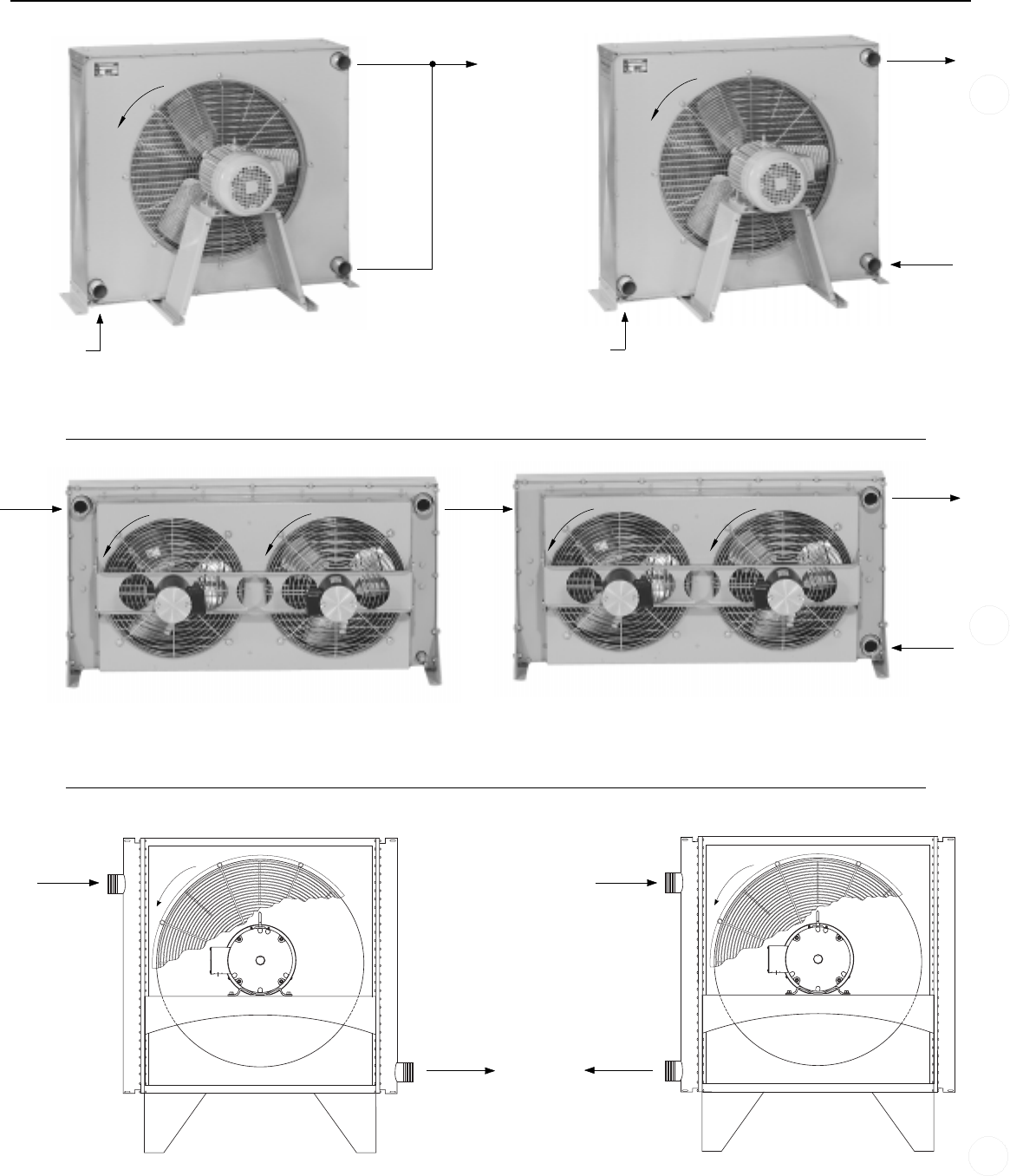
AIR COOLED HEAT EXCHANGERS PIPING HOOK-UP
AC, ACF & AOCH Series
ONE PASS
TWO PASS
ACA Series
EOC Series
ONE PASS TWO PASS
ONE PASS
F
a
n
r
o
t
a
t
i
o
n
TWO PASS
F
a
n
r
o
t
a
t
i
o
n
INLET
OUTLET
F
a
n
r
o
t
a
t
i
o
n
F
a
n
r
o
t
a
t
i
o
n
INLET
OUTLET
INLET
F
a
n
r
o
t
a
t
i
o
n
F
a
n
r
o
t
a
t
i
o
n
INLET
OUTLET
F
a
n
r
o
t
a
t
i
o
n
OUTLET
OUTLET
INLET
INLET
CAPPED
F
a
n
r
o
t
a
t
i
o
n
OUTLET
10

Copyright © 2001 American Industrial Heat Transfer, Inc.
LP Series
OUT
IN
IN or OUT
IN or OUT
AOMF
BM Series
Adjustable
brackets
OUT
IN
IN or OUT
IN or OUT
F
a
n
r
o
t
a
t
i
o
n
IN or OUT
IN or OUT
OUT
IN
AOM & AOMR Series
T
WO
P
ASS
S
INGLE
P
ASS
Adjustable
brackets
OUT
IN
IN or OUT
IN or OUT
AIR COOLED HEAT EXCHANGER PIPING HOOK-UP
OUT
IN
IN
OUT
IN
IN
OUT
OUT
11

Copyright © 2001 American Industrial Heat Transfer, Inc.
Insulation of boiler
or storage tank
Capillary
tubing
Tube Clip &
rubber gromet
1/2"-14 external
threads on spud
Wall or boiler or
storage tank
Immersion
Wall
Sensing Bulb
Spud screws into tapping
(reducer fitting may be
necessary to adapt spud
to tapping)
Sensing Bulb
Composition Disc
(slotted)
Packing Nut
Screws into tapping
in boiler or tank
Slotted brass washers
assembled in pairs
1/2" Capillary
compression
fitting
1/2"-14 External
threads on spud
Capillary
Tubing
ELECTRICAL TEMPERATURE CONTROLLER WITH BULB WELL ASSEMBLY (for Air/Oil Coolers)
SPECIFICATIONS:
A) Material: Copper
B) Power Limits:
1)
For three phase motor operation, use only with a magnetic starter, 125 VA
max. (VA =volts x amps)
2)For pilot duty, 125 VA max.
3)For direct connection to motor:
120v AC/8.0 amps max 230v AC/5.1 amps max
277v AC/4.2 amps max 460v AC/2.0 amps max
4)Temperature operating range: 55°F to 175°F.
APPLICATIONS (Temperature Controller)
The TC511 temperature controllers are designed to control the tempera-
ture of air or liquids in ducts, pipes, tanks, and boilers. Typical uses include
control of dampers and valves in heating, cooling, or heating-cooling sys-
tems. The TC511 has 1 spdt switch. It makes or breaks a circuit on a change
in temperature at the sensing bulb. Fast response models with adjustable
differential are available for duct installation. They respond approximately 4
times faster than standard models.
INSTALLATION
When installing this product:
1. Read instructions carefully. Failure to follow the instructions could
damage the product or cause a hazardous condition.
2. Check the ratings given in the instructions and on the product to make
sure the product is suitable for your application.
3. Installer must be a trained, experienced service technician.
4. After installation is complete, check out product operation as provided
in the instructions.
LOCATION AND MOUNTING.
The controller may be installed in any convenient position. Mount it
with 3 screws through the slotted holes in the back of the case. Be sure to
consider the length of the capillary before mounting the controller.
Install the sensing element where it is exposed to the average tempera-
ture of the controlled medium. The sensing bulb may be directly im-
mersed or mounted in a well. Fast response models must use the capillary
holder furnished with the device. The remote sensing bulb of standard
models should be held in place with a capillary holder, immersion well, or
compression fitting. Sharp bends or kinks in the capillary tubing affect the
efficiency of the controller and must be avoided. Excess capillary should
be carefully coiled and left directly beneath the controller.
NOTE: When pressure fittings are used in areas of vibration (such
as pipe lines) the bulb must be adequately supported.
OPERATION
As the temperature of the controlled medium falls below
the set point less differential, the TC511 switch makes
terminal R to B and energizes a normally close
solenoid valve to provide heat. In cooling applica-
tions, the TC511 makes terminal R to W as
the temperature rises above the set point,
energizing cooling equipment.
0.20
2.13
2.25
2.44
2.63
1.22
0.38
0.94
ø0.88 Knockout
Both ends
2.00
ø0.22 (3x)
ø0.37 (3x)
4.19
0.69
5.63
1.75
1.94
ELECTRICAL RATINGS:
TC511 models with adjustable differential:
TC511 models with fixed differential -125 VA at 120/208/240/
277 Vac.
MAXIMUM BULB PRESSURE: 50 psi (344.7 kPa) for direct
immersions.
AIR COOLED ACCESSORIES
12

Copyright © 2001 American Industrial Heat Transfer, Inc.
STANDARD TERMS AND CONDITIONS OF SALE (1/3)
All sales by American Industrial Heat Transfer Inc. ("Seller") to the party to whom a
Seller's Acknowledgment is addressed ("Purchaser") are subject to the following terms
and conditions in addition to the terms and conditions contained in any
acknowledgement or sales order confirming your order (“Seller’s Acknowledgement”).
Where terms of any such Seller’s Acknowledgement conflict with the following terms
and conditions, the terms and conditions of Seller’s Acknowledgement shall control.
These Terms and Conditions shall apply to all transactions between Seller and
Purchaser unless superseded by new Terms and Conditions delivered by Seller or by
the express terms and conditions contained in Seller's Acknowledgment.
Acceptance. All purchase orders are accepted by Seller at its General Offices in Zion,
Illinois. Seller's acceptance of any purchase order it receives is expressly limited to the
exact terms contained here and in this Seller's Acknowledgment. Additional or
different terms contained in Purchaser's offer or any attempt by Purchaser to vary any
of the terms here and in Seller's Acknowledgment shall be rejected but such proposal
shall not operate as a rejection of Purchaser's offer unless such variances are in the
terms of the description, quantity, price or delivery schedule of the goods or services to
be provided hereunder, in which case such additional or different terms shall be
deemed material and such offer shall be deemed accepted without said additional or
different terms or attempted variations. Acceptance by Seller of any purchase order
containing terms additional to or different from the terms contained in this Seller's
Acknowledgment or containing modifications of the terms contained here and in
Seller’s Acknowledgment shall not be deemed as assent to those additional, different or
modified terms. Purchaser's receipt of Seller's Acknowledgment without prompt
written objection thereto, or Purchaser's acceptance of all or any part of the goods or
services ordered from Seller, shall constitute assent by Purchaser to the terms
contained here and in Seller's Acknowledgment. If this Seller's Acknowledgment shall
be deemed an offer by Seller to sell goods or services to Purchaser, such offer is
expressly limited to the exact terms contained herein. The dispatch of a purchase order
by Purchaser shall then constitute Purchaser's acceptance of these Standard Terms and
Conditions of Sale and Seller's Acknowledgment. If this Seller's Acknowledgment is
deemed an offer as aforesaid, any proposal by Purchaser for additional or different
terms or any attempt by Purchaser to vary any of the terms of this Seller's Acknowledg-
ment in Purchaser's purchase order is hereby objected to and rejected; provided,
however, that any such proposal by Purchaser shall not operate as a rejection of Seller's
offer unless it contains variances in the terms of the description, quantity, price or
delivery of the goods or services to be provided hereunder, in which case any such
proposal shall be deemed material, and this Seller's Acknowledgment shall be deemed
accepted without said additional or different terms or attempted variations.
Payment Terms. The full amount billed or contracted for is due and payable thirty (30)
days from delivery of the goods or performance of services. A finance charge
computed at the periodic rate of one and one-half percent (1.5%) per month (which is
an annual rate of eighteen percent (18%)) on the unpaid balance will be made on
accounts not paid when due, and Purchaser agrees to pay such charges and pay
attorneys' fees if action is brought to collect from Purchaser. Unless otherwise
specified, 100% of the price quoted for any tooling is to be paid with the placement of
the order to Seller. Samples submitted shall be deemed approved and accepted if
written notice of rejection is not received within thirty (30) days after date of
submittal. Purchaser agrees that Seller shall have a possessory lien on all tools and
other property of Purchaser which is in Seller's possession for the total amount owing
by Purchaser to Seller for all tooling and other work and for all parts, materials and
services of all kinds supplied or rendered by Seller to Purchaser, which lien shall be
enforceable in the manner provided in the Uniform Commercial Code.
Taxes. Any tax which the Seller may be required to pay or collect through assessment
or otherwise, under any existing or future law upon or with respect to the sale,
purchase, delivery, transportation, storage, processing, use or consumption of any
goods or services described herein, including, without limitation, taxes upon or
measured by receipt from sales or services (but excluding taxes based upon the income
of Seller), shall be for the account of Purchaser and be added to the price of such goods
or services. Purchaser shall promptly pay the amount thereof to Seller upon demand
but may in lieu of such payment, furnish to Seller evidence of the issuance of tax
exemption certificates acceptable to the appropriate taxing authorities.
Prices. Except as otherwise provided, all price quotations are valid for thirty (30) days.
Prices are based on costs prevailing on the date of quotation and, therefore, are subject
to change at any time to reflect increased costs. Prices are quoted on samples,
blueprints, or drawings on hand, and any modification thereof subjects this quotation to
adjustment. Quotations are is based on the continuous production of the quantity
specified, smaller runs subject to increase in price. If higher quantity level is desired
by Purchaser, Seller will render a quotation based upon the revised requirements set
forth by Purchaser.
Credit. All orders are subject to the approval of Seller's Credit Department, and Seller
may at any time refuse to make shipment or delivery if Purchaser fails to fulfill the
terms and conditions of payment or fails to provide security satisfactory to Seller's
Credit Department. Seller reserves right to refuse or cancel credit and require full
payment prior to shipment. If in Seller's opinion the financial condition of Purchaser
at any time does not justify continuation of production or shipment on the terms of
payment specified, Seller may require full or partial payment in advance or such
further assurance as Seller shall require to justify such continued production or
shipment.
Default in Payment and Bankruptcy of Purchaser. If Purchaser fails to make payments
on any agreement between Purchaser and Seller in accordance with Seller's terms,
Seller, in addition to any other remedies available to it, may, at its option, (a) defer
further shipments until such payments are made and satisfactory credit arrangements
are reestablished, (b) cancel the unshipped balance of any order or (c) take any other
action available under applicable law. In the event of any proceedings, voluntary or
involuntary, in bankruptcy or insolvency by or against Purchaser, the inability of
Purchaser to pay its debts as they become due, or in the event of the appointment, with
or without Purchaser's consent, of an assignee for the benefit of creditors or of a
receiver, then Seller shall be entitled, in its sole discretion, to cancel the unshipped
balance of any order without any liability.
Transportation Charges. All prices, quotations, shipments and deliveries by Seller are
F.O.B. Seller's plant and risk of loss passes to Purchaser once goods are tendered for
such delivery. All transportation and other charges including handling fees are for the
account of Purchaser, including any increase or decrease in such charges prior to
shipment.
Method of Shipment. Method and route of shipment is at Seller's discretion, unless
Purchaser supplies explicit instructions, which are subsequently accepted by Seller in
writing. Seller does not assume responsibility for any damage directly or indirectly
resulting from delays in delivery. When parts are broken or damaged in transit from
Seller to Purchaser, it is considered the responsibility of Purchaser to file a claim with
the carrier for said breakage or damage. If the method of shipment specified by
Purchaser is deemed by Seller to be unavailable or otherwise unsatisfactory, Seller
reserves right to use an alternate method or route or both whether or not at a higher
cost to Purchaser. Seller shall promptly notify Purchaser of any such change. The risk
of loss or damage to the goods shipped shall pass to the Purchaser when the goods are
delivered to the carrier for shipment and Purchaser shall be responsible for insuring
such goods thereafter.
Producing or Shipping Point. Seller reserves right to produce and ship all or any part
of the goods specified in any order from any of its plants or facilities.
Force Majeure. Seller shall not be liable for any delay in the performance of orders, or
in the delivery or shipment of goods, or for any damages suffered by Purchaser as a
result of such delay when such delay is occasioned by causes beyond Seller's control.
Such causes shall include but are not limited to an act of God or the public enemy, fire,
explosion, flood, unusually severe weather, drought, war, riots, sabotage, vandalism,
accident, embargo, government priority, government action or failure of the govern-
ment to act when action is required, requisition or allocation or other action of any
governmental authority, interruption of or delay in transportation, inadequacy or
shortage or failure of supply of materials or equipment, breakdowns, non-scheduled
shutdowns for repairs, plant accidents, labor shortage, strikes, labor trouble, or by
compliance with any order or request of the United States Government or any officer,
department, agency, instrumentality or committee thereof. It is understood and agreed
that economic conditions affecting the ability or desirability of the performance of this
agreement by either party shall not be deemed to constitute "force majeure" circum-
stances as contemplated by this paragraph. The Seller shall have the right to cancel the
entire agreement with Purchaser or any part thereof in the event of the happening of
any such cause beyond the Seller's control without any resulting liability.
Good Delivery. Shipments made by Seller within a reasonable time after the specified
date of delivery shall constitute a good delivery. No right of cancellation shall accrue
to Purchaser based on such a delivery.
Permissible Variations. Goods shipped by Seller shall be within the limits and sizes
published by Seller, subject, however, to Seller's right to ship overages or underages in
accordance with Seller's standard practices and goods shipped by Seller will be subject
to standard variations provided such variations are non-functional or are not material in
nature.
LIMITED WARRANTY. SELLER MAKES NO WARRANTIES EXPRESSED OR
STANDARD TERMS AND CONDITIONS OF SALE
April 1, 2000 Supersedes all prior "Standard Terms And Conditions Of Sale"
13

Copyright © 2001 American Industrial Heat Transfer, Inc.
STANDARD TERMS AND CONDITIONS OF SALE (2/3)
IMPLIED, INCLUDING BUT NOT BY WAY OF LIMITATION, ANY IMPLIED
WARRANTY OF MERCHANTABILITY AND ANY IMPLIED WARRANTY OF
FITNESS FOR A PARTICULAR PURPOSE, ON ANY ORDER EXCEPT THAT
SELLER WARRANTS TITLE TO ALL GOODS FURNISHED BY SELLER AND
EXCEPT THAT SELLER WARRANTS FOR A PERIOD OF ONE YEAR FROM THE
DATE MARK LOCATED ON THE SELLER'S IDENTIFICATION TAG THAT ALL
GOODS DESCRIBED ON SELLER'S ACKNOWLEDGMENT OF PURCHASER'S
PURCHASE ORDER WILL BE MANUFACTURED IN ACCORDANCE WITH THE
SPECIFICATIONS, IF ANY, SET FORTH IN SAID PURCHASE ORDER AND
EXPRESSLY ACCEPTED IN SELLER'S ACKNOWLEDGMENT SUBJECT TO
SELLER'S STANDARD MANUFACTURING VARIATIONS AND PRACTICES. IN
THE CASE OF COMPONENTS OR ACCESSORIES FURNISHED BY SUPPLIERS
TO SELLER, PURCHASER'S WARRANTY FROM SELLER SHALL BE LIMITED
TO THE WARRANTY OF THE COMPONENT OR ACCESSORY SUPPLIER. THE
FOREGOING WARRANTIES ARE THE SOLE AND EXCLUSIVE WARRANTIES
APPLICABLE TO THE GOODS DELIVERED, AND ALL OTHER WARRANTIES,
EXPRESS OR IMPLIED, INCLUDING WITHOUT LIMITATION ANY WAR-
RANTY OF MERCHANTABILITY, ARE HEREBY EXPRESSLY DISCLAIMED
AND NEGATED. WITHOUT LIMITING THE GENERALITY OF THE FOREGO-
ING, PURCHASER ACKNOWLEDGES THAT SELLER'S PRODUCTS ARE NOT
PACKAGED OR PROTECTED FOR LONG PERIODS OF STORAGE AND THUS
MAY CORRODE OR RUST OVER TIME.
Damaged Goods. If any goods should arrive at Purchaser's destination in a damaged
condition or should a shortage occur, Purchaser shall immediately report the damage or
shortage to the delivering carrier and to Seller. Any loss or shortage occasioned by
damage or otherwise occurring in transit will be for account of Purchaser. Allegedly
defective goods or parts are to be returned by Purchaser to a destination specified by
Seller, freight charges prepaid by Purchaser. All repairs and replacements are subject
to verification and inspection by Seller. Seller shall not be responsible for costs of de-
installation and re-installation of goods or parts returned.
Claims. Claims respecting the condition of goods, compliance with specifications or
any other matter affecting goods shipped to Purchaser must be made promptly and,
unless otherwise agreed to in writing by Seller, in no event later than twenty-one (21)
days after receipt of the goods by Purchaser. Purchaser shall set aside, protect and
hold such goods without further processing until Seller has an opportunity to inspect
and advise of the disposition, if any, to be made of such goods. In no event shall any
goods be returned, reworked or scrapped by Purchaser without the express written
authorization of Seller. If field service is rendered by the Seller at Purchaser's request
and the alleged defect is found not to be with the Seller's product, component or
accessory, the Purchaser shall pay for the time and expenses of the field representative.
Bills for service, labor or other expenses that have been incurred by the Purchaser,
their customer or agent, without approval or authorization by the Seller, will not be
accepted. Changes or repairs attempted or made in the field without Seller's written
authorization automatically void all warranties.
LIMITATION OF PURCHASER'S REMEDIES. PURCHASER'S REMEDIES WITH
RESPECT TO ANY CLAIM ARISING OUT OF ANY ORDER, ANY GOODS
DELIVERED PURSUANT TO ANY ORDER AND EXPRESSLY ACCEPTED IN
SELLER'S ACKNOWLEDGMENT, OR SELLER'S PERFORMANCE IN CONNEC-
TION WITH ANY ORDER, INCLUDING, WITHOUT LIMITATION, ANY CLAIM
ARISING OUT OF ANY RECALL, DEFECT OR ALLEGED DEFECT IN ANY
GOODS OR SERVICES FURNISHED BY SELLER, SHALL BE LIMITED
EXCLUSIVELY TO THE RIGHT OF REPAIR OR REPLACEMENT OF SUCH
GOODS OR SERVICES, AT SELLER'S OPTION. WITHOUT IN ANY WAY
LIMITING THE GENERALITY OF THE FOREGOING, IN NO EVENT SHALL
SELLER BE LIABLE FOR ANY CONSEQUENTIAL OR INCIDENTAL DAM-
AGES, INCLUDING, WITHOUT LIMITATION, ANY LOSS OF ANTICIPATED
PROFITS INCURRED BY PURCHASER WITH RESPECT TO ANY GOODS OR
SERVICES FURNISHED BY SELLER, OR ANY DAMAGES ARISING FROM
INJURIES TO PERSONS AS A RESULT OF PURCHASER'S OR A THIRD PARTY'S
NEGLIGENCE. SELLER'S WARRANTY DOES NOT COVER FAILURES
RESULTING FROM THE IMPROPER INSTALLATION, MOUNTING DESIGN OR
APPLICATION OR FROM CORROSION. THE PROVISIONS OF THIS PARA-
GRAPH ARE A MATERIAL TERM OF THIS TRANSACTION.
Warranty Procedures. If Purchaser experiences a problem with Sellers goods and
believes that it is covered by Seller's warranty, or Purchaser has equipment that needs
to be repaired or replaced, contact Seller through Purchaser's local distributor. The
basic information that Purchaser will need to begin the process is the complete
nameplate data. Products will not be accepted for return unless an RGA (Return Goods
Authorization) number has been assigned by Seller and the product for return or repair
is shipped prepaid. Products returned for warranty evaluation must be complete
(without missing components), and unaltered (not disassembled, manipulated cleaned
or the like). The product(s) must have the original model tag fully intact. Products
returned for warranty consideration are subject to a $100 minimum fee plus any
additional handling charges in the event that the reason for the return is not covered by
Seller's warranty. Additional handling fees are to cover the cost of failure analysis,
testing and the like. All handling charges will be waived for products that are subject
to a valid warranty claim. Products to be returned for warranty are to be shipped
prepaid via Seller assigned carrier.
Returns and Returns Procedures. In order to return a product for credit, test, or repair,
Purchaser must follow the procedures outlined in this paragraph and, in the case of
repairs, the immediately following paragraph. Failure to follow return procedures
could result in lost items, delays, additional service charges, warranty denial or refusal
of shipment. All items being returned to Seller must be accompanied with an RGA
(Return Goods Authorization) number for identification purposes. Products returned
without a clearly marked RGA number will not be processed. RGA numbers can be
obtained only through Seller. Products being returned for restock and credit must be
complete (without missing components), unused, and within one year of original
factory purchase. The products must have the original model tag fully intact. Returned
products must be free of dents, customer applied paint, rust, or any permanent
alterations of any type. Products shipped for restock are to be shipped prepaid. Heat
exchangers being returned for credit are subject to a 30% restocking charge. Other
items such as, without limitation, valves and temperature controls are subject to a 15%-
50% restocking charge to be determined by the products’ usage or salability.
Restocking charges are applied to cover the cost or the retest and refitting equipment to
new condition. Seller will issue credit only after a thorough inspection has been
performed. NO DEBITS WILL BE HONORED UNTIL AFTER RETURN INSPEC-
TION APPROVAL.
Repairs. Products being returned for repair, refit, test or similar matters must be
drained completely prior to shipment. Purchaser must clearly label the product with
information to identify the Purchaser and Seller's RGA number. Purchaser should also
include a note with instructions for service, failure, nature of problem and the fluids
that are used inside of the product. A base handling charge of $100 will be applied for
each product regardless of condition that it is in when returned for evaluation.
Products being returned for evaluation must be shipped prepaid. Quotations for repair,
test, cleaning, and similar matters will be issued shortly after return to Seller. All
products returned shall be considered abandoned by Purchaser and may be scrapped if
the Purchaser or shipper renders no disposition instructions after 45 days from
notification by written quotation. Seller does not warranty any repaired products under
any circumstances. Products repaired and the repairs are the sole responsibility of the
owner of the products. Products sent to Seller for evaluation will be returned, upon
request and at the owner’s expense.
Quality Assurance. Seller shall have no obligation to ensure that any goods or services
purchased from Seller meet any special quality assurance specifications and/or other
requirements unless such specifications and/or other requirements are set forth in
Purchaser's purchase order or separately provided in writing to Seller and, in either
case, expressly accepted in this Seller's Acknowledgment and Purchaser represents that
goods which it purchases from Seller will not be applied by Purchaser or resold by
Purchaser for application to, any critical end use, including, without limitation, use in
connection with or in any way related to the construction or operation of a nuclear
facility unless the appropriate specification and/or other requirement for such end use
is set forth in Purchaser's purchase order and is expressly accepted in a separate writing
by Seller. In the event that any such goods or any services supplied by Seller in
connection therewith are applied to a critical end use without the appropriate
specification and/or other requirement therefor having been set forth in Purchaser's
purchase order and expressly accepted in a separate writing by Seller, Purchaser shall
indemnify and hold Seller harmless against any and all damages or claims for damages
made by any person for any injury, fatal or nonfatal, to any person or for any damage
to the property of any person incident to or arising out of such application, including,
without limitation, any loss resulting from radioactive, toxic, explosive, or other
hazardous properties of source material, special nuclear material, or by-product
material as such terms are defined in the Atomic Energy Act of 1954 or any law
amendatory thereof or regulations adopted pursuant thereto. The Seller reserves the
right to improve its products through changes in design or material, as it may deem
desirable without being obligated to incorporate such changes in products of prior
manufacture.
Cancellation. Purchaser Orders cannot be cancelled without cause by Purchaser
without the express written consent of the Seller. Should Purchaser attempt to cancel
an order without cause, Purchaser shall reimburse Seller against all loss occasioned by
such cancellation, including loss of anticipatory profits and liability for commitments
made by Seller relating to the Purchase Order and shall purchase any existing
inventory and work in process which Seller has in its possession to fulfill Seller's
existing orders for Purchaser at the time of cancellation. As used herein, "cause" shall
mean a material breach of Seller's duties and obligations hereunder and the failure to
cure such breach after Purchaser notifies Seller of such breach and affords Seller a
reasonable time to cure same.
14

Copyright © 2001 American Industrial Heat Transfer, Inc.
Confidentiality and Publicity. Purchaser shall consider all information furnished by
Seller to be confidential and shall not disclose any such information to any person, firm
or corporation, other than Purchaser's or Seller's employees, subcontractors or
government inspectors, unless authorized to do so by Seller in writing. Purchaser shall
not disclose in any manner to third parties, including, without limitation to, advertis-
ing, or publishing concerns, Seller's identity or the identity of any subsidiaries or
affiliates of Seller. Unless otherwise agreed to in writing, no commercial, financial or
technical information disclosed in any manner or at any time by Purchaser to Seller
shall be deemed secret or confidential and Purchaser shall have no rights against Seller
with respect thereto except such rights as may exist under patent laws.
Tooling. If and to the extent any Purchase Order relates to the purchase of tools, jigs,
die fixtures, equipment, drawings and specifications (collectively, "tooling") or
specifically requires tooling for completion by Seller, then Seller shall at all times be
and remain the owner of such tooling and shall bear the risk of loss and be responsible
for insuring same. If any Purchase Order requires the development of such tooling,
then the price quoted by Seller is based on a minimum production of a specified
quantity of parts from such tooling and, in the event Purchaser does not ultimately
purchase such quantity of parts, an equitable adjustment in the purchase price for
products shall be made to reflect such lower quantity and Seller's unamortized cost of
the tooling so produced. Seller's price quotation is based upon estimated usage of
tooling but no representations or warranties are made by Seller that the tooling so built
will ultimately be capable of producing product in accordance with such anticipated
usage. Purchaser agrees to pay for changes in tooling made necessary by changes in
specifications accepted by Seller, such changes to be made at Purchaser's risk. Parts
produced from Purchaser's supplied tooling cannot be guarantied by Seller. Purchaser
provided tooling is not insured and Seller shall not be responsible or liable for any loss
or damage thereto or for any materials or equipment owned or furnished by Purchaser.
Purchaser shall be solely responsible for insuring such tooling and Purchaser waives
any claim or right of subrogation it may have against Seller arising out of Seller's
failure to insure such tooling. Seller reserves the right to charge Purchaser the
reasonable costs and expenses of refurbishing any tooling if so required by Seller to
fulfill any Purchase Order. When for a period of one (1) year no orders are received
for parts to be produced from tooling, Seller may notify Purchaser in writing at
Purchaser's last known address in Seller's files that tooling is no longer proprietary to
Purchaser and, with respect to Purchaser supplied tooling, such tooling shall become
Seller’s property or, at Seller’s option, Seller man return such tooling to Purchaser at
Purchaser’s expense.
Prototypes. If this Purchase Order relates to the production of a prototype by Seller for
or on behalf of Purchaser, (a) such prototypes will be manufactured in accordance with
Purchaser's specifications including material selection and (b) actual product produced
by Seller may vary from such prototype in a non-material and non-functional manner.
Seller's sole liability in the event it is unsuccessful in producing a prototype in
accordance with Purchaser's specifications shall be limited to the purchase price paid
by Purchaser with respect thereto. Purchaser shall be responsible for the cost of all
tooling necessary for the development of the prototype as provided in the paragraph
Captioned “Tooling” above.
Technical Assistance and Advice. Seller's warranty shall not be enlarged and no
obligation or liability shall arise out of Seller's rendering of technical assistance,
technical advice facilities, service or recommendations made by Seller in connection
with Purchaser's purchases of the goods hereunder. Said technical services, advice,
assistance or recommendations made by Seller or any representative of Seller
concerning any use or application of any goods furnished hereunder is believed to be
reliable, but SELLER MAKES NO WARRANTY, EXPRESS OR IMPLIED, AND
THE SAME ARE HEREBY EXPRESSLY DISCLAIMED as to the same and the
results to be obtained. Purchaser assumes all responsibility for loss or damage
resulting from the use of any such goods.
Indemnification. Purchaser agrees to indemnify, save harmless and defend Seller from
and against any and all liability for loss, damage or injury to person or property in any
manner arising out of or incident to the performance of any Seller's Acknowledgment
or other sale by Seller or its servants, employees, agents or representatives. Without
limiting the generality of the foregoing, Purchaser will indemnify and hold harmless
Seller, its officers, employees, agents, successors, assigns, customers and users of its
products from and against any and all losses, expenses, claims, suits and liabilities
(including incidental and consequential damages and court costs and attorneys fees)
arising as a result of any claim that the manufacture, use, sale or resale of goods
delivered by Seller in accordance with Purchaser's specifications or designs infringes
on any patent, utility model, industry design, copyright or other intellectual property
rights in any country. Without limiting the generality of the paragraph captioned
“LIMITATION OF PURCHASER’S REMEDIES” above, in the case of any claim of
infringement or the sale of products is enjoined, Seller shall have no obligation to
procure for Purchaser the right to continue using such products or to replace same with
equivalent non-infringing products or to modify the products so they become non-
STANDARD TERMS AND CONDITIONS OF SALE (3/3)
infringing.
Setoffs. Purchaser shall make no deduction or setoff for any claim arising out of or from
any transaction with Seller nor shall Purchaser take any discount, credit or allowance
without Seller's written consent.
Assignment. Purchaser shall not assign any order or any interest therein without the written
consent of Seller. Any such actual or attempted assignment without Seller's prior written
consent shall entitle Seller to cancel such order upon written notice to Purchaser.
Termination. Seller may terminate any order or any part thereof for any reason at Seller's
convenience upon written notice to Purchaser. Upon such termination, Purchaser agrees to
waive all claims for damages including, without limitation, any loss of anticipated profits,
and to accept as its sole remedy for termination the reasonable additional costs of obtaining
substitute goods of the same quantity and quality, provided that in no event shall such costs
exceed the price of the order or part thereof so terminated as stated on Seller's Acknowledg-
ment. Any claim for adjustment not asserted within sixty (60) days from the date of such
termination shall be deemed to have been waived by Purchaser.
Allocation of Risk. Purchaser acknowledges that these Standard Terms and Conditions of
Sale and Seller's Acknowledgment allocates risks with respect to goods and/or services sold
to Purchaser and this risk allocation is reflected in the prices to be paid by Purchaser for
said goods and/or services purchased hereunder. Purchaser warrants that it has read this
provision, understands it and is bound by its terms.
Packaging. Seller will use all reasonable means to comply with any packaging, loading or
bracing requirements specified in any order. Seller will charge for compliance with
Purchaser's special requirements in accordance with Seller's price list for extras in effect at
time of shipment. If no packaging, loading or bracing requirements are specified by
Purchaser, Seller shall comply with the minimum requirements customarily applied by
Seller to the method of transportation used for such goods.
Entire Agreement. These Standard Terms and Conditions of Sale and Seller’s Acknowledg-
ment and any other documents referred to on the face thereof constitute the entire
agreement between Seller and Purchaser.
Modification. No addition or modification of the terms and conditions of these Standard
Terms and Conditions of Sale and Seller’s Acknowledgment shall be binding on Seller
unless specifically agreed to by Seller in writing.
Waiver. Seller's failure to insist on performance of any of these Standard Terms and
Conditions of Sale and Seller's Acknowledgment or to exercise any right or privilege or
Seller's waiver of any breach hereunder shall not thereafter waive any other terms,
conditions, or privileges, whether of the same or similar type.
Governing Law. Seller and Purchaser's agreement shall be governed by and interpreted in
accordance with the laws of the State of Illinois of the United States of America.
Manufacture, shipment and delivery are subject to any prohibition, restriction, priority,
allocation, regulation or condition imposed by or on behalf of the United States of America
or any other governmental body with appropriate jurisdiction which may prevent or
interfere with fulfillment of any order.
Re-orders. Re-orders, if accepted by Seller, are considered as placed under the same terms
and conditions as Purchaser's previous order, when such orders are not placed pursuant to a
formal written proposal and acceptance.
Disclosure. Seller shall have the right to disclosure of the identity of Purchaser and the
nature of the work Seller is performing on Purchaser's behalf to Seller's customers and
prospective customers and in any promotional materials provided such disclosure does not
contain any confidential and proprietary information concerning Purchaser.
DISPUTES. SELLER AND PURCHASER AGREE TO SUBMIT ANY DISPUTES
REGARDING ANY ORDER, ANY GOODS DELIVERED PURSUANT TO ANY ORDER
AND EXPRESSLY ACCEPTED IN SELLER'S ACKNOWLEDGMENT, OR SELLER'S
PERFORMANCE IN CONNECTION WITH ANY ORDER, INCLUDING WITHOUT
LIMITATION SELLER'S LIMITED WARRANTY OBLIGATION, TO MEDIATION BY
AN INDEPENDENT MEDIATOR TO BE MUTUALLY AGREED UPON BY SELLER
AND PURCHASER. THE COST OF SUCH MEDIATION SHALL BE BORNE
EQUALLY BY SELLER AND PURCHASER. IN THE EVENT SUCH MEDIATION
DOES NOT RESOLVE THEIR DISPUTE, SELLER AND PURCHASER AGREE TO
SUBMIT SUCH DISPUTE TO AN INDEPENDENT ARBITRATOR, TO BE MUTUALLY
AGREED UPON BY SELLER AND PURCHASER OR, OTHERWISE, CHOSEN BY THE
MEDIATOR. SELLER AND PURCHASER AGREE THAT ALL MEDIATION AND
ARBITRATION SHALL BE CONDUCTED IN ZION, ILLINOIS. THE NON-PREVAIL-
ING PARTY AT THE ARBITRATION SHALL PAY THE PREVAILING PARTY'S
ATTORNEYS' FEES AND COSTS INCURRED IN PARTICIPATING IN THE ARBITRA-
TION.
15

Copyright © 2001 American Industrial Heat Transfer, Inc.
AOCH Series with screen & Serviceable Core
®
• Industrial high capacity air/oil heat exchanger available in 8
standard sizes with electric or hydraulic drive.
AC,ACHM & ACF Series
• Industrial air/oil heat exchanger available in 8 standard sizes with
electric or hydraulic drive.
ACA Series
• Heavy-duty Serviceable Core
®
air cooled air after-coolers for
compressor sizes up to 500 HP.
AVAILABLE PRODUCTS
URCS Series
• U-tube heat exchangers for steam services with removable tubes
bundle in copper, 316L SS, or 90/10 Cu Ni.
CS Series
• Heat exchangers in copper, 316L SS, or 90/10 Cu Ni.
EOC Series with electric motor & filter as an option
.
• Versatile industrial/mobile grade heat exchanger available with
optional filter, AC, DC, and hydraulic drives.
American Industrial Heat Transfer, Inc. 3905 Route 173 - Zion, IL 60099 Tel: (847) 731-1000
16

20
Copyright © 2004 American Industrial Heat Transfer, Inc.
tel: 1 (847) 731-10003905 Route 173 Zion, IL 60099 www.aihti.comfax: 1 (847) 731-1010
note: AIHTI reserves the right to make reasonable design changes without notice.
21
Copyright © 2004 American Industrial Heat Transfer, Inc.
tel: 1 (847) 731-10003905 Route 173 Zion, IL 60099 www.aihti.comfax: 1 (847) 731-1010
note: AIHTI reserves the right to make reasonable design changes without notice.
ACCESSORIES shell & tube heat exchangers
56T THERMOSTATIC MODULATING WATER VALVE WITH BULB WELL ASSEMBLY
(for Shell & Tube Heat Exchangers And Air/Oil Coolers)
SPECIFICATIONS
Sizes 0.375", 0.50", 0.75", 1.00", 1.25" FPT
Fluid Pressure 125psi (max.)
Standard Temperature 40° - 100° F., 60° - 140° F., 100° - 175° F., 125° - 200° F.,
140° - 240° F., 200° - 275°F.
Body Brass alloy casting
Valve Parts Brass alloy
Standard Capillary Length 6’ & 20’ foot
Standard Bulbs For 3/8" & 1/2" valve sizes: 5/8" x 6 with 3/4" union
connections. For 3/4" & 1" valve sizes: 5/8" x 8-1/4"
with 3/4" union connections.
Stainless steel construction available.
Standard Bulb Mounting 3/4" NPT
Seat Disk Buna-N-replaceable
Seat Bead Stainless Steel - replaceable
Length for 3/4" - 1 1/4"
9.5"
Length for 1/2" - 3/8"
5.5"
APPLICATION INFORMATION
• Built for rugged machine tool and hydraulic applications.
• Adjustable temperature range to meet your requirements.
• Quick response to temperature changes.
• Extra heavy-duty direct acting bellows for longer service.
Note: Please consult factory if a non-cataloged temperature is required.
Part Number
Description
Size NPT Temp. Range
310-1001 3/8” 60
O
F - 140
O
F
310-1004 1/2” 60
O
F - 140
O
F
310-1008 3/4” 60
O
F - 140
O
F
310-1014 1” 60
O
F - 140
O
F
310-1020 1-1/4” 60
O
F - 140
O
F
310-1046 1-1/2” 60
O
F - 140
O
F
310-1047 2” 60
O
F - 140
O
F
310-1025 3/8” 100
O
F - 175
O
F
310-1005 1/2” 100
O
F - 175
O
F
310-1010 3/4” 100
O
F - 175
O
F
310-1015 1” 100
O
F - 175
O
F
310-1026 1-1/4” 100
O
F - 175
O
F
Bulb Well
Part Number
Brass
Part Number
Stainless Steel
310-2001 310-2003
310-2001 310-2003
310-2002 310-2004
310-2002 310-2004
310-2002 310-2004
310-2001 310-2003
310-2001 310-2003
310-2002 310-2004
310-2002 310-2004
310-2002 310-2004
Thermostatic Modulating Water Valve
The type 56-T valve gives smooth regulation of water and other fluids. It's designed for the most rugged application. For example: hydraulic
power packaging equipment, hydraulic presses, plastic molding equipment, and anywhere reliability in temperature control is demanded.
The type 56-t valve is a better designed product that won't leak or chatter. To insure dependability, every valve is factory tested three times
in different temperature baths. Extra performance can be expected of the bellows also. They are direct acting with sturdy walls, and the inner
spring is zinc coated. The seat beads are stainless steel to resist the erosive effects of wire drawing and provide longer life for your needs.
Additional features include mounting in any position, Buna-N seat disc, and manual flushing.
Description
Part Number Size NPT
301-0004 3/8” NPT
301-0003 1/2” NPT
Zinc Anode List Prices
3/8" NPT Thread
1/2" NPT Thread
1.84"
1.00"
2.70"
1.15"
0.86"
0.50"ø
0.63"ø
0.75"
1.00"
1.75"
3/8" NPT Thread
1/2" NPT Thread
1.84"
1.00"
2.70"
1.15"
0.86"
0.50"ø
0.63"ø
0.75"
1.00"
1.75"

40
Copyright © 2004 American Industrial Heat Transfer, Inc.
tel: 1 (847) 731-10003905 Route 173 Zion, IL 60099 www.aihti.comfax: 1 (847) 731-1010
note: AIHTI reserves the right to make reasonable design changes without notice.
41
Copyright © 2004 American Industrial Heat Transfer, Inc.
tel: 1 (847) 731-10003905 Route 173 Zion, IL 60099 www.aihti.comfax: 1 (847) 731-1010
note: AIHTI reserves the right to make reasonable design changes without notice.
Part Number
Description
Part Number
Description
Size NPT Material Size NPT Material
310-3002 1/2”
Cast Iron
310-3001 3/8”
Brass
310-3004 3/4” 310-3003 1/2”
310-3006 1” 310-3005 3/4”
310-3008 1-1/4” 310-3007 1”
310-3009 1-1/2” 310-3013 1-1/4”
310-3010 2” 310-3014 1-1/2”
310-3011 2-1/2” 310-3015 2
310-3012 3” 310-3016 2-1/2”
310-3017 3”
APPLICATIONS & SPECS. ("Y" Strainers)
These strainers are engineered for water or steam, and are adapt-
able for many other uses. Cleaning is accomplished by simply
removing a pipe plug without disconnecting any piping. Or, if
it is desirable to clean without interrupting service, a blow-off
valve can be connected to the clean-out opening. Note: Pumps,
control valves, traps, or other equipment controlling the flow
of liquids or gases require proper protection with strainers for
trouble free operation.
18 - Y BRASS STRAINERS
The 18 - Y strainer body is a sturdy red brass casting. Standard
units have 50 mesh brass wire screens. Brazing connections are
available on special order instead of pipe threads.
20 - Y STRAINERS
The 20 - Y strainer has a heavy cast iron body with accurately
machined pipe thread inlet and outlet (National Pipe Thread
N.P.T.). It contains a strainer screen of 0.02" thick brass with
100, 1/16" perforations per inch.
C
D
A
Pipe Thread
INLET
OUTLET
E
Clean-out
Opening
Pipe Thread
B
MODEL
SIZE
A
(NPT)
DIMENSIONS (Inches)
WT.
(lbs.)
B C
D
E
(NPT)
18 - Y
0.38"
0.50"
0.75"
1.00"
2.50"
2.50"
3.50"
3.50"
2.63"
2.63"
3.75"
3.75"
2.00"
2.00"
2.75"
2.75"
0.25"
0.25"
0.50"
0.50"
0.75
0.75
1.75
1.75
20 - Y
0.50"
0.75"
1.00"
1.25"
1.50"
2.00"
4.00"
4.00"
4.75"
6.00"
6.00"
8.13"
3.25"
3.25"
4.38"
5.13"
5.13"
6.38"
2.50"
2.50"
3.38"
3.88"
3.88"
4.63"
0.38"
0.38"
0.75"
0.75"
0.75"
0.75"
1.75
1.75
4.00
4.75
4.75
13.00
PRESSURE RATINGS, ALL MODELS: 125lbs. per Sq.In.
"Y" STRAINER (for Shell & Tube Heat Exchangers And Air/Oil Coolers)
ACCESSORIES shell & tube heat exchangers

144
Copyright © 2004 American Industrial Heat Transfer, Inc.
tel: 1 (847) 731-10003905 Route 173 Zion, IL 60099 www.aihti.comfax: 1 (847) 731-1010
note: AIHTI reserves the right to make reasonable design changes without notice.
145
Copyright © 2004 American Industrial Heat Transfer, Inc.
tel: 1 (847) 731-10003905 Route 173 Zion, IL 60099 www.aihti.comfax: 1 (847) 731-1010
note: AIHTI reserves the right to make reasonable design changes without notice.
Insulation of boiler
or storage tank
Capillary
tubing
Tube Clip
&
rubber gromet
1/2"-14 external
threads on spud
Wall or boiler or
storage tank
Immersion
Wall
Sensing Bulb
Spud screws into tapping
(reducer fitting may be
necessary to adapt spud
to tapping)
Sensing Bulb
Composition Disc
(slotted)
Packing Nut
Screws into tapping
in boiler or tank
Slotted brass washers
assembled in pairs
1/2" Capillary
compression
fitting
1/2"-14 External
threads on spud
Capillary
Tubing
ELECTRICAL TEMPERATURE CONTROLLER WITH BULB WELL ASSEMBLY (for Air/Oil Coolers)
0.20
2.13
2.25
2.44
2.63
1.22
0.38
0.94
ø0.88 Knockout
Both ends
2.00
ø0.22 (3x)
ø0.37 (3x)
4.19
0.69
5.63
1.75
1.94
SPECIFICATIONS:
A) Material: Copper
B) Power Limits:
1)For three phase motor operation, use only with
a magnetic starter, 125 VA max. (VA =volts x amps)
2)For pilot duty, 125 VA max.
3)For direct connection to motor:
120v AC/8.0 amps max 230v AC/5.1 amps max
277v AC/4.2 amps max 460v AC/2.0 amps max
4)Temperature operating range: 55°F to 175°F.
APPLICATIONS (Temperature Controller)
The TC511 temperature controllers are designed to control the temperature of air
or liquids in ducts, pipes, tanks, and boilers. Typical uses include control of dampers
and valves in heating, cooling, or heating-cooling systems. The TC511 has 1 spdt
switch. It makes or breaks a circuit on a change in temperature at the sensing bulb.
Fast response models with adjustable differential are available for duct installation.
They respond approximately 4 times faster than standard models.
INSTALLATION
When installing this product:
1. Read instructions carefully. Failure to follow the instructions could damage the
product or cause a hazardous condition.
2. Check the ratings given in the instructions and on the product to make sure the
product is suitable for your application.
3. Installer must be a trained, experienced service technician.
4. After installation is complete, check out product operation as provided in the
instructions.
ELECTRICAL RATINGS:
TC511 models with adjustable differential:
TC511 models with fixed differential -125 VA at 120/208/240/277 Vac.
MAXIMUM BULB PRESSURE: 50 psi (344.7 kPa) for direct immersions.
LOCATION AND MOUNTING.
The controller may be installed in any convenient position. Mount it with 3 screws through
the slotted holes in the back of the case. Be sure to consider the length of the capillary before
mounting the controller.
Install the sensing element where it is exposed to the average temperature of the controlled
medium. The sensing bulb may be directly immersed or mounted in a well. Fast response
models must use the capillary holder furnished with the device. The remote sensing bulb
of standard models should be held in place with a capillary holder, immersion well,
or compression fitting. Sharp bends or kinks in the capillary tubing affect the
efficiency of the controller and must be avoided. Excess capillary should be
carefully coiled and left directly beneath the controller.
NOTE: When pressure fittings are used in areas of vibration (such
as pipe lines) the bulb must be adequately supported.
OPERATION
As the temperature of the controlled medium falls below
the set point less differential, the TC511 switch makes
terminal R to B and energizes a normally close solenoid
valve to provide heat. In cooling applications, the TC511
makes terminal R to W as the temperature rises above
the set point, energizing cooling equipment.
ACCESSORIES air / oil heat exchangers
Part Number Description
310-4001 TC-511 with 5-Foot Capallary Tube & Bulb Well
310-4002 TC-511 with 20-Foot Capallary Tube & Bulb Well
310-2005 Replacement Bulb Well TC-511
Length for 3/4" - 1 1/4"
9.5"
Length for 1/2" - 3/8"
5.5"

188
Copyright © 2004 American Industrial Heat Transfer, Inc.
tel: 1 (847) 731-10003905 Route 173 Zion, IL 60099 www.aihti.comfax: 1 (847) 731-1010
note: AIHTI reserves the right to make reasonable design changes without notice.
189
Copyright © 2004 American Industrial Heat Transfer, Inc.
tel: 1 (847) 731-10003905 Route 173 Zion, IL 60099 www.aihti.comfax: 1 (847) 731-1010
note: AIHTI reserves the right to make reasonable design changes without notice.
Part Number
Description
Part Number
Description
Temp. Setting Size NPT Temp. Setting Size NPT
310-7029 100
O
F
1/2”
310-7014 100
O
F
1-1/2”
310-7023 110
O
F 310-7034 110
O
F
310-7030 120
O
F 310-7035 120
O
F
310-7043 140
O
F 310-7012 140
O
F
310-7006 160
O
F 310-7001 160
O
F
310-7031 100
O
F
3/4”
310-7002 100
O
F
2”
310-7032 110
O
F 310-7024 110
O
F
310-7022 120
O
F 310-7036 120
O
F
310-7042 140
O
F 310-7020 140
O
F
310-7007 160
O
F 310-7010 160
O
F
310-7033 100
O
F
1”
310-7037 100
O
F
3”
310-7026 110
O
F 310-7038 110
O
F
310-7028 120
O
F 310-7039 120
O
F
310-7021 140
O
F 310-7041 140
O
F
310-7008 160
O
F 310-7040 160
O
F
“3-Way” Thermostatic Valve
Part Number Description
310-4001 TC-511 with 5-Foot Capallary Tube & Bulb Well
310-4002 TC-511 with 20-Foot Capallary Tube & Bulb Well
310-2005 Replacement Bulb Well TC-511
Adjustable Electrical Temperature Switch (see page 224)
Thermostatic valves utilize the principle
of expanding wax, which in the semi-liquid state
undergoes large expansion rates within a relative-
ly narrow temperature range. The self contained
power element activates a stainless steel sliding
valve which provides positive three-way actions.
All thermostatic valves are factory set at prede-
termined temperatures; no further adjustments
are necessary. A wide range of temperatures are
available for water and oil temperature control ap-
plications.
On starting, the total fluid flow is in a
by-pass mode. As fluid temperature rises to the
control range some fluid is diverted to the cooling
system. As fluid temperature continues to in-
crease, more flow is diverted, and when in a fully
stroke condition all fluid flow is positively directed
to the cooling system. Thermostatic valves may
be used for either mixing or diverting applications.
In normal operation fluid temperatures are con-
trolled to within a few degrees.
Standard thermostatic valve housings are
made from high quality grey iron castings.
ACCESSORIES air / oil heat exchangers
