
CLI Administration Guide
Published May, 2023
Version NOS 52x

Legal Notices
Copyright
©
2019 - 2022 by Hewlett Packard Enterprise Development LP
Notices
The information contained herein is subject to change without notice. The only warranties for Hewlett Packard Enterprise products
and services are set forth in the express warranty statements accompanying such products and services. Nothing herein should be
construed as constituting an additional warranty. Hewlett Packard Enterprise shall not be liable for technical or editorial errors or
omissions contained herein.
Confidential computer software. Valid license from Hewlett Packard Enterprise required for possession, use, or copying. Consistent
with FAR 12.211 and 12.212, Commercial Computer Software, Computer Software Documentation, and Technical Data for Com-
mercial Items are licensed to the U.S. Government under vendor's standard commercial license.
Links to third-party websites take you outside the Hewlett Packard Enterprise website. Hewlett Packard Enterprise has no control
over and is not responsible for information outside the Hewlett Packard Enterprise website.
Hewlett Packard Enterprise believes in being unconditionally inclusive. If terms in this document are recognized as offensive or
noninclusive, they are used only for consistency within the product. When the product is updated to remove the terms, this document
will be updated.
Acknowledgments
Intel
®
, Itanium
®
, Pentium
®
, Intel Inside
®
, and the Intel Inside logo are trademarks of Intel Corporation in the United States and other
countries.
Microsoft
®
and Windows
®
are either registered trademarks or trademarks of Microsoft Corporation in the United States and/or
other countries.
Adobe
®
and Acrobat
®
are trademarks of Adobe Systems Incorporated.
Java
®
and Oracle
®
are registered trademarks of Oracle and/or its affiliates.
UNIX
®
is a registered trademark of The Open Group.
All third-party marks are property of their respective owners.
Publication Date
Tuesday May 30, 2023 02:39:29
Document ID
gch1580761875832
Support
All documentation and knowledge base articles are available on HPE InfoSight at https://infosight.hpe.com. To register for
HPE InfoSight, click the Create Account link on the main page.
Email: [email protected]
For all other general support contact information, go to https://www.hpe.com/us/en/services/nimble-storage.html.
Legal Notices ii
Documentation Feedback: [email protected]
Contents
The Array Command Line Interface............................................................................................12
Accessing the CLI.....................................................................................................................................................................................................................................12
CLI Commands...........................................................................................................................................................................................................................................13
Array Overview...............................................................................................................................14
The HPE Nimble Storage Array.......................................................................................................................................................................................................14
Array Features............................................................................................................................................................................................................................................14
IOPS and MiB/s Limits on Volumes and Folders....................................................................................................................................................................16
Horizontal Scaling....................................................................................................................................................................................................................................16
Relationship of Groups, Pools, Arrays, Folders, and Volumes.......................................................................................................................17
Pools...............................................................................................................................................................................................................................................18
Feature Support on iSCSI and Fibre Channel Arrays...........................................................................................................................................................19
Integration....................................................................................................................................................................................................................................................19
Wellness and DNA....................................................................................................................................................................................................................................20
Access Controls..........................................................................................................................................................................................................................................20
User Permissions.....................................................................................................................................................................................................................20
CHAP Accounts........................................................................................................................................................................................................................21
iSCSI Initiator Groups............................................................................................................................................................................................................21
Fibre Channel Initiator Groups........................................................................................................................................................................................21
VLAN Segmentation and Tagging................................................................................................................................................................................22
Major Workflows.............................................................................................................................23
Updating array OS Workflow.............................................................................................................................................................................................................23
Provisioning Storage Volumes and Performance Policies Workflow.........................................................................................................................23
Setting Up Replication Workflow.....................................................................................................................................................................................................23
Creating a vVol Datastore Workflow.............................................................................................................................................................................................24
Restoring Snapshot Data from Clones Workflow...................................................................................................................................................................24
Hardware and Software Updates................................................................................................26
Upgrades and Updates..........................................................................................................................................................................................................................26
Hardware Upgrades...............................................................................................................................................................................................................26
Updates.........................................................................................................................................................................................................................................26
Find the Array OS Version...................................................................................................................................................................................................................26
Update the Array OS..............................................................................................................................................................................................................................27
Verify the Array OS Update................................................................................................................................................................................................................29
Contents 3
Network Configuration..................................................................................................................30
Network Configuration Profiles........................................................................................................................................................................................................30
Draft Network Configuration Profile............................................................................................................................................................................30
Create a Draft Network Configuration Profile........................................................................................................................................................30
Validate a Network Configuration Profile.................................................................................................................................................................31
Activate a Network Configuration Profile.................................................................................................................................................................31
Delete a Network Configuration Profile.....................................................................................................................................................................31
IP Addresses................................................................................................................................................................................................................................................32
Add an IP Address..................................................................................................................................................................................................................32
Edit an IP Address..................................................................................................................................................................................................................33
Delete an IP Address.............................................................................................................................................................................................................34
Subnets...........................................................................................................................................................................................................................................................35
Subnet Traffic Types.............................................................................................................................................................................................................35
Subnet Traffic Assignments.............................................................................................................................................................................................35
IP Address Zones in Subnets............................................................................................................................................................................................36
Add a Subnet.............................................................................................................................................................................................................................37
Edit a Subnet.............................................................................................................................................................................................................................38
Remove a Subnet....................................................................................................................................................................................................................38
Routes..............................................................................................................................................................................................................................................................39
Add a Static Route..................................................................................................................................................................................................................39
Edit a Static Route..................................................................................................................................................................................................................40
Delete a Static Route.............................................................................................................................................................................................................40
Configure the Default Gateway......................................................................................................................................................................................41
Network Interfaces...................................................................................................................................................................................................................................41
Add an iSCSI Interface to a Subnet...............................................................................................................................................................................41
Remove an iSCSI Interface from a Subnet................................................................................................................................................................42
Set a Fibre Channel Interface Administrative State............................................................................................................................................42
iSCSI Host Connection Methods......................................................................................................................................................................................................43
Automatic iSCSI Host Connections...............................................................................................................................................................................43
Manual iSCSI Host Connections......................................................................................................................................................................................43
VLAN Support and VLAN Tagging................................................................................................................................................................................................44
About VLANs.............................................................................................................................................................................................................................44
About VLAN Tagging...........................................................................................................................................................................................................45
Array Groups...................................................................................................................................47
Group Leader Array.................................................................................................................................................................................................................................47
Backup Group Leader Array...............................................................................................................................................................................................................47
Secondary Management IP Address and Backup Group Leader................................................................................................................48
Methods for Setting Up a Secondary Management IP Address to Use for a Backup Group Leader ....................................48
Migrate Group Leader Functions to Backup Leader............................................................................................................................................................48
Adding Arrays to a Group....................................................................................................................................................................................................................49
Add an Unconfigured Array to Group.........................................................................................................................................................................49
Contents 4
Add a Configured Array to a Group (Group Merge)...........................................................................................................................................50
Group Information....................................................................................................................................................................................................................................55
Default Group Settings..........................................................................................................................................................................................................................55
Modify Global Security Policies.......................................................................................................................................................................................55
Modify the Default Inactivity Timeout........................................................................................................................................................................56
Modify the Default Space Reservation.......................................................................................................................................................................57
Modify the Date, Time, and Time Zone......................................................................................................................................................................57
Modify DNS Settings.............................................................................................................................................................................................................57
Multiprotocol Array Groups................................................................................................................................................................................................................58
Enable Multiprotocol Access to a Group...................................................................................................................................................................58
Disable Multiprotocol Access to a Group..................................................................................................................................................................59
Switch a Volume from iSCSI to Fibre Channel Protocol....................................................................................................................................59
Switch a Volume from Fibre Channel to iSCSI Protocol....................................................................................................................................59
Initiator Groups...............................................................................................................................61
iSCSI Initiator Groups.............................................................................................................................................................................................................................61
Create an iSCSI Initiator Group.......................................................................................................................................................................................61
Edit an iSCSI Initiator Group ............................................................................................................................................................................................62
Delete an iSCSI Initiator Group........................................................................................................................................................................................63
Add an Initiator to an iSCSI Initiator Group.............................................................................................................................................................63
Remove an Initiator from an iSCSI Initiator Group..............................................................................................................................................64
Fibre Channel Initiator Groups..........................................................................................................................................................................................................64
Create a Fibre Channel Initiator Group.......................................................................................................................................................................64
Add a Target Driven Zone Port to an Initiator Group ......................................................................................................................................65
Remove a Target Driven Zone Port from an Initiator Group.........................................................................................................................65
Edit a Fibre Channel Initiator Group............................................................................................................................................................................66
Delete a Fibre Channel Initiator Group.......................................................................................................................................................................66
Add an Initiator to a Fibre Channel Initiator Group............................................................................................................................................67
Remove an Initiator from a Fibre Channel Initiator Group..............................................................................................................................67
Initiator Group Access Control Lists..............................................................................................................................................................................................68
Add an Initiator Group ACL to a Volume..................................................................................................................................................................68
Remove an Initiator Group ACL from a Volume....................................................................................................................................................69
Volumes............................................................................................................................................70
Clones, Replicas, and Snapshots......................................................................................................................................................................................................70
Logical versus Physical Space...........................................................................................................................................................................................................70
Space Management.................................................................................................................................................................................................................................70
Volume Reserve.......................................................................................................................................................................................................................71
Thin Provisioning....................................................................................................................................................................................................................71
Volume Usage Limits............................................................................................................................................................................................................71
A Note on Defragmentation...............................................................................................................................................................................................................71
Cloning Space Considerations...........................................................................................................................................................................................................72
Protecting Data Using Snapshots...................................................................................................................................................................................................72
Contents 5
Create a Volume........................................................................................................................................................................................................................................72
Edit a Volume..............................................................................................................................................................................................................................................74
Change a Volume's State......................................................................................................................................................................................................................75
Clone a Volume from a Snapshot....................................................................................................................................................................................................75
Restore a Volume from a Snapshot...............................................................................................................................................................................................76
Delete a Volume........................................................................................................................................................................................................................................76
Volume Pinning..........................................................................................................................................................................................................................................77
Pinnable Flash Capacity......................................................................................................................................................................................................77
Volume Pinning Caveats.....................................................................................................................................................................................................77
Unable to Pin a Volume.......................................................................................................................................................................................................79
Pin a Volume..............................................................................................................................................................................................................................79
Unpin a Volume........................................................................................................................................................................................................................79
Performance Policies..............................................................................................................................................................................................................................80
Create a Performance Policy............................................................................................................................................................................................80
Create a Performance Policy with Deduplication Enabled..............................................................................................................................80
Edit a Performance Policy..................................................................................................................................................................................................81
Delete a Performance Policy.............................................................................................................................................................................................81
Group Scoped iSCSI Target................................................................................................................................................................................................................82
Change iSCSI Volume Scope from VST to GST.....................................................................................................................................................83
Change iSCSI Volume Scope from GST to VST.....................................................................................................................................................83
Virtual Volumes (vVols)................................................................................................................85
vCenter Server............................................................................................................................................................................................................................................85
Register a vCenter Plugin with vCenter Server ....................................................................................................................................................85
Unregister a vCenter Plugin..............................................................................................................................................................................................85
Add a vCenter Server............................................................................................................................................................................................................85
Edit a vCenter Server............................................................................................................................................................................................................86
Remove a vCenter Server...................................................................................................................................................................................................86
Virtual Machines........................................................................................................................................................................................................................................86
Viewing Accidentally Deleted VMs...............................................................................................................................................................................86
Permanently Delete a VM..................................................................................................................................................................................................86
Restore a VM.............................................................................................................................................................................................................................87
Folders..............................................................................................................................................88
Relationship of Folders, Pools, and Volumes............................................................................................................................................................................88
Create a Folder.........................................................................................................................................................................................................................88
Edit a Folder...............................................................................................................................................................................................................................89
Delete a Folder..........................................................................................................................................................................................................................89
Deduplication..................................................................................................................................90
Deduplication on Hybrid Arrays......................................................................................................................................................................................................90
Pool-Level Deduplication (Default)...............................................................................................................................................................................................91
Managing Deduplication Capacity..................................................................................................................................................................................................92
Contents 6
Domains..........................................................................................................................................................................................................................................................92
Enable All-Volume (Pool-Level) Deduplication.....................................................................................................................................................92
Enable Deduplication Determined by Performance Policy.............................................................................................................................93
Enable Per-Volume Deduplication................................................................................................................................................................................93
Disable Per-Volume Deduplication...............................................................................................................................................................................93
Create a Performance Policy with Deduplication Enabled..............................................................................................................................94
Clone a Volume with Deduplication Enabled..........................................................................................................................................................94
Snapshots.........................................................................................................................................95
Snapshots Overview................................................................................................................................................................................................................................95
Snapshots and Daylight Savings Time.......................................................................................................................................................................95
Snapshot Rate Limits..............................................................................................................................................................................................................................95
Volume and Snapshot Usage.............................................................................................................................................................................................................96
Pending Deletions and Snapshot Usage...................................................................................................................................................................96
Automatic and Manual Snapshots..................................................................................................................................................................................................97
Take a Manual Snapshot.....................................................................................................................................................................................................97
Clone a Snapshot......................................................................................................................................................................................................................................97
Change a Snapshot's State..................................................................................................................................................................................................................98
Delete a Snapshot....................................................................................................................................................................................................................................98
Hidden Snapshots....................................................................................................................................................................................................................................98
Snapshot Consistency............................................................................................................................................................................................................................99
Snapshot Framework..............................................................................................................................................................................................................................99
Managed and Unmanaged Snapshots.......................................................................................................................................................................................100
Managed Snapshots...........................................................................................................................................................................................................100
Unmanaged Snapshots ....................................................................................................................................................................................................100
Time-To-Live (TTL) Feature.........................................................................................................................................................................................100
List Unmanaged Snapshots...........................................................................................................................................................................................100
Enable the Global TTL Feature....................................................................................................................................................................................100
Disable the Global TTL Feature..................................................................................................................................................................................101
Modify the TTL of a Specific Snapshot...................................................................................................................................................................101
Modify the TTL of a Snapshot Collection..............................................................................................................................................................101
Verify TTL Enablement and Expiration Values of Unmanaged Snapshots.......................................................................................102
NSs Snapshots.........................................................................................................................................................................................................................................102
Working with Online Snapshots....................................................................................................................................................................................................102
Identify Online Snapshots Using the NimbleOS CLI........................................................................................................................................103
Migrate Data From an Online Snapshot to a New Volume..........................................................................................................................103
Storage Pools................................................................................................................................105
Pool Considerations.............................................................................................................................................................................................................................105
Create a Storage Pool.........................................................................................................................................................................................................................107
Add or Remove Arrays from a Storage Pool.........................................................................................................................................................................108
Merge Storage Pools............................................................................................................................................................................................................................108
Volume Moves.........................................................................................................................................................................................................................................109
Contents 7
Move a Volume from One Storage Pool to Another........................................................................................................................................109
Move a Volume from One Folder to Another......................................................................................................................................................110
Stop a Volume Move in Progress................................................................................................................................................................................110
Delete a Storage Pool..........................................................................................................................................................................................................................111
Data Protection.............................................................................................................................112
Volume Collections...............................................................................................................................................................................................................................112
Volume Collections and Multiple Replication Partners..................................................................................................................................113
Create a Volume Collection............................................................................................................................................................................................113
Protect a Standalone Volume.......................................................................................................................................................................................114
Modify a Volume Collection...........................................................................................................................................................................................115
Delete a Volume Collection............................................................................................................................................................................................115
Protection Templates..........................................................................................................................................................................................................................116
Create a Protection Template.......................................................................................................................................................................................116
Edit a Protection Template............................................................................................................................................................................................117
Delete a Protection Template.......................................................................................................................................................................................118
Replication.....................................................................................................................................119
What is Replication?.............................................................................................................................................................................................................................119
Snapshot Replication and Synchronous Replication.........................................................................................................................................................120
Link Management and Resynchronization with Synchronous Replication..........................................................................................................122
Replication Partners and How Replication Works..............................................................................................................................................................122
Add Replication to a Volume Collection.................................................................................................................................................................123
Create a Replication Partner..........................................................................................................................................................................................124
Modify a Replication Partner.........................................................................................................................................................................................125
Delete a Replication Partner..........................................................................................................................................................................................125
Test the Connection between Replication Partners........................................................................................................................................125
Synchronous Replication...................................................................................................................................................................................................................126
Synchronous Replication Prerequisites and Limitations..............................................................................................................................126
Out-of-Sync Volumes.........................................................................................................................................................................................................127
Volume Names and Replication...................................................................................................................................................................................127
Configuring Synchronous Replication on a Volume Collection.................................................................................................................127
Configuring Synchronous Replication: Serial Numbers and ACLs..........................................................................................................128
Unconfigure Synchronous Replication....................................................................................................................................................................128
Reconfigure Synchronous Replication.....................................................................................................................................................................128
Automatic Switchover (ASO)........................................................................................................................................................................................129
Synchronous Replication and Manual Failovers..................................................................................................................................................................133
Overview of Manual Failover Steps When Group Leader Is Unreachable..........................................................................................134
Overview of Manual Failover Steps When the Backup Group Leader is Unreachable................................................................135
Perform a Manual Takeover of the Group Leader Array..............................................................................................................................135
Remove Synchronous Replication from the Downstream Partner..........................................................................................................136
Add Synchronous Replication .....................................................................................................................................................................................137
Replication Strategy.............................................................................................................................................................................................................................138
Contents 8
Replication and Folders....................................................................................................................................................................................................141
Replication Seeding..............................................................................................................................................................................................................................142
Replica Details ........................................................................................................................................................................................................................................143
Replication Bandwidth Limits.........................................................................................................................................................................................................143
Set Overall Bandwidth Limits for Replication......................................................................................................................................................144
Remove Overall Bandwidth Limits for Replication...........................................................................................................................................144
Configure Bandwidth Limitations for a Replication Partner.......................................................................................................................144
Modify Per-Partner Replication Bandwidth Limits...........................................................................................................................................144
Security..........................................................................................................................................146
Role-Based Access Control..............................................................................................................................................................................................................146
View User Information.......................................................................................................................................................................................................146
Add a User Account............................................................................................................................................................................................................146
Edit a User Account............................................................................................................................................................................................................147
Change Your Account Information............................................................................................................................................................................148
Change Your Account Password.................................................................................................................................................................................148
Reset a User Account Password..................................................................................................................................................................................149
Enable a User Account......................................................................................................................................................................................................149
Disable a User Account.....................................................................................................................................................................................................149
Remove a User Account...................................................................................................................................................................................................150
Permission Levels................................................................................................................................................................................................................150
Access Control with Active Directory........................................................................................................................................................................................156
View Information about the Active Directory Domain...................................................................................................................................157
Guidelines for Working with Arrays and Active Directory ..........................................................................................................................157
Join an Active Directory Domain.................................................................................................................................................................................158
Leave an Active Directory Domain............................................................................................................................................................................158
User Authentication and Logon..................................................................................................................................................................................158
Enable Active Directory Domain Authentication...............................................................................................................................................159
Disable Active Directory Domain Authentication.............................................................................................................................................159
Active Directory Groups...................................................................................................................................................................................................159
Troubleshooting the Active Directory.....................................................................................................................................................................161
CHAP Authentication..........................................................................................................................................................................................................................161
Create a CHAP Account...................................................................................................................................................................................................162
Assign a CHAP User to a Volume...............................................................................................................................................................................162
Modify a CHAP User...........................................................................................................................................................................................................162
Delete a CHAP User............................................................................................................................................................................................................162
Login Banner............................................................................................................................................................................................................................................162
Edit the Login Banner........................................................................................................................................................................................................163
Show the Login Banner.....................................................................................................................................................................................................163
Reset the Login Banner....................................................................................................................................................................................................164
Encryption of Data at Rest...............................................................................................................................................................................................................164
Enable Encryption................................................................................................................................................................................................................165
Secure Sockets Layer Certificates................................................................................................................................................................................................166
Create and Import a Custom Certificate or Certificate Signing Request.............................................................................................166
Contents 9
Delete a Certificate..............................................................................................................................................................................................................167
Create a Custom Certificate Chain.............................................................................................................................................................................168
Specify a Certificate Chain to Use to Authenticate HTTPS and API Services.................................................................................170
Multihost Access....................................................................................................................................................................................................................................171
Using MPIO..............................................................................................................................................................................................................................171
MPIO for Windows...............................................................................................................................................................................................................171
MPIO for Linux.......................................................................................................................................................................................................................171
Secure SMTP............................................................................................................................................................................................................................................171
Configure Email Alerts......................................................................................................................................................................................................171
Monitoring Your Arrays..............................................................................................................173
Monitor Space Usage...........................................................................................................................................................................................................................173
Monitor Performance...........................................................................................................................................................................................................................173
Monitor Interface Traffic...................................................................................................................................................................................................................174
Monitor Replication..............................................................................................................................................................................................................................174
Syslog...........................................................................................................................................................................................................................................................174
Enable Syslog.........................................................................................................................................................................................................................175
Disable Syslog........................................................................................................................................................................................................................175
Audit Log Management.....................................................................................................................................................................................................................175
Audit Log Panel.....................................................................................................................................................................................................................176
Facets Panel............................................................................................................................................................................................................................176
Summary Table.....................................................................................................................................................................................................................176
User Management................................................................................................................................................................................................................177
Disaster Recovery........................................................................................................................178
Handover Overview..............................................................................................................................................................................................................................178
Perform a Handover.............................................................................................................................................................................................................................179
Make a Replica Available to Applications................................................................................................................................................................................179
Promote a volume collection .........................................................................................................................................................................................................180
Demote a volume collection............................................................................................................................................................................................................180
Claim a volume........................................................................................................................................................................................................................................181
Array Administration..................................................................................................................182
Configure Email Alerts........................................................................................................................................................................................................................182
Diagnostics for Nimble Analytics.................................................................................................................................................................................................183
Enable Autosupport............................................................................................................................................................................................................183
Disable Autosupport..........................................................................................................................................................................................................183
Manually Send an Autosupport...................................................................................................................................................................................183
Enable a Secure Tunnel....................................................................................................................................................................................................183
Configure a Proxy Server.................................................................................................................................................................................................183
Usage Analytics......................................................................................................................................................................................................................................184
Enable or Disable Usage Analytics ...........................................................................................................................................................................184
Usage Analytics and Software Updates..................................................................................................................................................................184
Contents 10
Change an Array Name......................................................................................................................................................................................................................184
Set Up SNMP............................................................................................................................................................................................................................................185
Fail Over a Controller .........................................................................................................................................................................................................................185
Shut Down an Array.............................................................................................................................................................................................................................185
Alarm Management.....................................................................................................................187
List Alarms.................................................................................................................................................................................................................................................187
Enable and Disable the Alarm Feature.....................................................................................................................................................................................188
Acknowledge Alarms...........................................................................................................................................................................................................................188
Unacknowledge Alarms......................................................................................................................................................................................................................189
Change an Alarm Reminder.............................................................................................................................................................................................................190
Delete Alarms...........................................................................................................................................................................................................................................190
Events.............................................................................................................................................191
Event Severity Levels..........................................................................................................................................................................................................................191
View Events...............................................................................................................................................................................................................................................191
Events and Alert Messages..............................................................................................................................................................................................................192
Audit Logs.....................................................................................................................................243
Audit Log Messages.............................................................................................................................................................................................................................243
System Limits and Timeout Values..........................................................................................255
System Limits...........................................................................................................................................................................................................................................255
Timeout Values.......................................................................................................................................................................................................................................258
Firewall Ports................................................................................................................................261
Configure Firewall Ports....................................................................................................................................................................................................................261
Regulatory and Safety Information..............................................................................................................................................................................................................266
Regulatory Warnings...........................................................................................................................................................................................................................266
Battery Safety..........................................................................................................................................................................................................................................266

The Array Command Line Interface
This document deals with procedures to manage the array and to automate common tasks using the array OS command line
interface (CLI). If you want to manage your array using the GUI, refer to the GUI Administration Guide. Not all procedures can
be performed with both the CLI and the GUI.
Accessing the CLI
Procedure
1. Open an SSH client, such as PuTTY or OpenSSH.
2. Enter the host name or IP address of the array.
If you are asked to accept the authorization key, type yes.
3. Log into the array with the username and the password you created when configuring the array.
The connection is made and you can now run the array CLI commands. For example, typing array --list displays the name,
serial, model, version, and status of the array:
$ array --list
c20-array2 AA-102081 CS220 3.1.988.0-354313-opt reachable
Typing array --info c20-array2 displays other information about the array:
$ array --info c20-array2
Model: CS220
Extended Model: CS220-4G-12T-320F
Serial: AA-102081
Version: 3.1.988.0-354313-opt
All-Flash: No
Array name: c20-array2
Supported configuration: Yes
Link-local IP address: 169.254.54.168
Group ID: 3815276604473015474
Member GID: 1
Group Management IP: 10.18.120.51
1G/SFP NIC: 4/0
Total array capacity (MiB): 7606708
Total array usage (MiB): 0
Total array cache capacity (MiB): 305276
Volume usage (MiB): 0
Volume compression: 1.00X
Volume space saved (MiB): 0
Snapshot usage (MiB): 0
Snapshot compression: 1.00X
Snapshot space reduction: 1.00X
Snapshot space saved (MiB): 0
Pending Deletes (MiB): 0
Available space (MiB): 7606708
Member of pool: default
Status: reachable
For more information about the command line interface, type man and the command of interest. For example, type man
array for information about the array command. Also see the Command Reference.
The Array Command Line Interface 12
Documentation Feedback: [email protected]

CLI Commands
To see the complete list of commands for managing the Nimble Array, refer to the Command Line Reference and the man
pages. In the Nimble documentation, bracketed subparameters are optional and unbracketed parameters are required.
You can also type ? at the command prompt to display a list of available commands, as shown in the following example:
Nimble OS $ ?
? folder pool timezone
alert group prottmpl useradmin
array halt reboot userauth
auditlog help route usersession
cert initiatorgrp setup vcenter
chapuser ip shelf version
ctrlr migration snap vm
date netconfig snapcoll vmwplugin
disk nic software vol
encryptkey partner sshkey volcoll
failover pe stats
fc perfpolicy subnet
Type man or help for a command to see details for that command. For example, typing man snap shows you all the suboptions
and variables for the snap command. Typing snap --help displays a less detailed list of all options.
The Array Command Line Interface 13
Documentation Feedback: [email protected]

Array Overview
The array seamlessly merges high-performance, compressed storage with capacity-optimized snapshot storage and
WAN-efficient replication while it also serves the following functions:
• Provides a seamless combination of storage and backup with efficient disaster recovery
• Enables data restoration based on snapshots
• Offers data protection through Recovery Point Objective (RPO) and Recovery Time Objective (RTO) metrics
• Simplifies storage and snapshot management
• Binds multiple arrays into a single management group
The HPE Nimble Storage Array
HPE Nimble Storage arrays are engineered for high performance using flash, for low cost using dense, capacity-optimized
disks, and for easy installation and administration.
HPE Nimble Storage solutions are built on the patented Cache Accelerated Sequential Layout (CASL
™
) architecture. CASL
leverages the lightning-fast random read performance of flash and the cost-effective capacity of hard disk drives. Data written
to the array is compressed and then stored in the disk-drive layer. HPE Nimble Storage arrays take advantage of multi-core
processors to provide high-speed inline variable-block compression without introducing noticeable latency. CASL also
incorporates efficiency features like cloning and integrated snapshots to store and serve more data in less space.
Data that is frequently accessed is tracked in the Nimble index, which ensures that frequently and recently accessed data is
also held in the large adaptive flash layer. A copy of all data in the flash layer also remains safely in the disk-drive layer to
ensure reliability, but now it can be accessed with the high performance and low latency made possible by flash technology.
Nimble Storage arrays provide:
• Higher storage efficiency to reduce the storage footprint by 30 to 75 percent
• Non-disruptive scaling to fit changing application needs through increased performance, or capacity, or both
• Maximized data and storage availability with integrated data protection and disaster recovery
• Simplified storage management and reduced day-to-day operational overhead
Nimble arrays are easy to install and manage. Consolidation of storage and backup, automatic failover, reusable schedules
based on application usage, and application integration are combined with a clean, intuitive GUI that improves the ease of
administration. For automation ease, a command-line interface (CLI) and RESTful API are also provided.
Array Features
Arrays provide features to enhance performance, value, and ease of use. The all-inclusive features described in this
documentation do not require extra licensing.
BenefitFunctionFeature
Core Functionality
Accelerates read operations, with sub-
millisecond latency
Reads active data from flash cache, which
is populated on writes or first read
Dynamic Caching
Accelerates writes as much as 100x, and
gets sub-millisecond latency and optimal
disk utilization
Coalesces random writes and sequential-
ly writes them to disk as a full stripe
Write-Optimized Data Layout
Array Overview 14
Documentation Feedback: [email protected]

BenefitFunctionFeature
Reduces capacity needs by 30-75%, de-
pending on the workload, with no perfor-
mance impact
Always-on inline compression for all
workloads
Universal Compression
Pools storage, shares free space, and
maximizes utilization
Allocates disk space to a volume only as
data is written; thin provision "stun" is
supported to add greater flexibility
Thin Provisioning
Improves file copy speedInteracts with storage devices to move
data through high-speed storage net-
works
Offloaded Data Transfer (ODX) for Win-
dows
Scales performance to manage large
amounts of active data
Non-disruptively upgrade controllers or
swap in higher capacity SSDs
Scale Performance
Increases storage capacity to 100s of TB
per system
Non-disruptively add external disk
shelves
Scale Capacity
Retains months of frequent snapshots,
which improves RPO with no perfor-
mance impact. Eliminates backup win-
dows and speeds up restores, which im-
proves RTO.
Backs up and restores data using point-
in-time, space-efficient snapshots taken
at regular intervals
Instant Snapshot and Recovery
Deploys affordable and verifiable disaster
recovery and efficiently backs up remote
sites over the WAN
Replicates the compressed data changes
to the secondary site for disaster recov-
ery
WAN-efficient Replication
Allows a switch to forward that frame
only to the appropriate VLAN
Part of the 802.1Q frame header contain-
ing a VLAN ID between 1 and 4094 that
identifies the VLAN to which the frame
belongs
VLAN Tagging
Creates clones in seconds and saves disk
space, which is ideal for VDI and
test/development environments
Creates copies of existing active volumes
without needing to copy data
Zero-Copy Clones
Host and Application Integration
Eliminates the need to manually tune
storage and data protection configura-
tions
Predefined policies for block size,
caching, compression, and data protec-
tion for Microsoft applications and
VMware virtual machines
Custom Application Profiles
Takes application-consistent backups
and simplifies data protection for Ex-
change and SQL Server
HPE Storage Driver for the Microsoft VSS
framework for consistent backup
Windows VSS Enablement
Manages storage from vCenter and takes
consistent backups of virtual machines
Monitors, provisions, and takes snap-
shots from VMware vCenter
VMware Integration
Simplifies disaster recovery, including
testing failover/failback
Supports disaster recovery automation
for VMware including failover/failback
VMware Site Recovery Manager Adapter
Management and Support
Spots and remedies potential issues to
maximize uptime, performance, and uti-
lization (no user data is accessed or col-
lected by DNA)
Real-time monitoring and analysis; sends
alerts on critical issues
Proactive Wellness and DNA
Array Overview 15
Documentation Feedback: [email protected]

BenefitFunctionFeature
Reduces burden on IT staff and quickly
resolves problems
Allows remote troubleshooting, configu-
ration, and problem resolution
Secure Remote Support
Maximizes uptime and user productivity
through continuous availability
Upgrades software with no disruption to
applications
Non-Disruptive Upgrades
Note: Recovery Point Objective (RPO) and Recovery Time Objective (RTO) are among the most important parameters
of a disaster recovery plan.
• RPO: The point-in-time to which systems and data must be recovered after an outage. The interval reflects the
amount of data loss a business can survive.
• RTO: The amount of time it takes to recover systems and data after an outage. The interval reflects the amount
of downtime a business can survive.
For RPO and RTO, a shorter time interval is better.
IOPS and MiB/s Limits on Volumes and Folders
You can set both IOPS (input/output requests per second) and MiB/s (mebibytes per second) limits when you set up a Quality
of Service policy for a volume or Storage Policy-Based Management (SPBM) for Virtual Volumes.
You specify the IOPS and MBps limits separately. The input/output requests are throttled when either the IOPS limit or the
MBps limit is met.
The default upper bound value for both the IOPS and the MiB/s is unlimited. The lower bound for IOPS is 256 requests. The
lower bound for the MiB/s value is calculated as greater than or equal to the IOPS limit multiplied by the volume block size.
This way the MiB/s value does not throttle the IOPS for the volume.
If the volume contains folders, then the IOPS and MiB/s limits work as an aggregate. The input/output requests to the volumes
under the folder are throttled when the cumulative IOPS of all the volumes under that folder exceeds the folder IOPS limit or
when the cumulative throughput of all the volumes under that folder exceeds the folder MiB/s limit. When this happens, all
the volumes are throttled equally.
You can set these limits when you create or edit either a volume or a folder. You can set separate limits for both volumes and
folders. You can view the limits for volumes and folders on the Performance tab at:
Manage > Data Storage > Performance
If you are creating or editing a folder, you can set the limits at the folder level that are in addition to the volume-level limits.
The default limits are at the volume level. You can view the limits on the Folder tab at:
Manage > Data Storage > Folder
You can monitor the throughput and bandwidth for the array, the volumes, and the folders by selecting:
Monitor > Performance
Horizontal Scaling
Scale-out, often referred to as horizontal scaling, means adding arrays to a group. Performance and capacity scale linearly as
you add arrays to the group. Grouping multiple arrays so that they can be managed as one entity provides significant
manageability benefits, because it appears as if you are managing a single large array. Scale-out simplifies load balancing and
capacity management, as well as hardware and software life-cycle management.
From an organizational standpoint, scale-out establishes a group of merged systems upon which storage pools can be developed.
Volumes are created within pools that can span multiple physical arrays. A volume might exist on one array or span multiple
arrays in a group by virtue of how the pool is configured.
Array Overview 16
Documentation Feedback: [email protected]

Scale-out is a peer-to-peer technology where each array can operate independently, but can be managed as a single pool of
storage. With scale-out, you not only add more disk and flash memory, but also CPU, system memory, network links, and so
on.
Scale-out requires that all arrays in a group have the same version of array software installed.
Relationship of Groups, Pools, Arrays, Folders, and Volumes
A group is a collection of one to four arrays that are physically connected. Logically, they represent a single storage entity to
aggregate performance and capacity, and to simplify management. Arrays in the group can be iSCSI, Fibre Channel, or
multiprotocol (iSCSI and Fibre Channel). A group contains one or more disjoint pools. For groups of arrays, data can be striped
across the arrays in the same pool. For most administrative tasks, a group looks and feels like a single array. You administer
the group by connecting to its management IP address, hosted by one of the arrays in a group.
A single-array group is formed when you configure a array.
Figure 1: Relationships of Groups, Pools, Arrays, Folders, and Volumes in Single-array Groups
41 FolderGroup
2 5Storage Pool Volume
3 Array
A group is scaled-out, or expanded to a multi-array group, by adding unconfigured or configured arrays to the group. Adding
a configured array to a group is also known as a group merge.
Array Overview 17
Documentation Feedback: [email protected]

Figure 2: Relationships of Groups, Pools, Arrays, Folders, and Volumes in Multi-array Groups
41 FolderGroup
2 5Storage Pool Volume
3 Array
You can remove an array that is part of a storage pool by evacuating the data from the array and then removing the array
from the pool. When you need to remove an array from a group, you can evacuate the data to another array in the group (for
example, moving a volume), provided there is enough space for the data that is stored on the array being removed.
Pools
A storage pool confines data to a subset of the arrays in a group. A storage pool is a logical container that contains one or
more member arrays in which volumes reside. The system stripes and automatically rebalances data of resident volumes over
the members across the pool. Storage pools dictate physical locality and striping characteristics. A member array can only be
a part of one storage pool. Note the following:
• Volumes and their respective snapshots and clones reside within a pool and are tied to a specific pool.
Volumes are also referred to as logical units (LUNs). On an array, LUNs are exposed as volumes.
• You can migrate (move) volumes between different pools.
• Volume collections are not tied to pools and can contain volumes that reside in different pools.
Use single-array pools under the following conditions:
• Fault isolation is a priority
• Linux hosts, or any hosts that do not have a supported HPE Storage Connection Manager available, can access the arrays
Consider using multi-array pools under the following conditions:
• Scaling performance and capacity, as well as consolidating management, are priorities
• Windows and ESX hosts that have a supported Connection Manager available can access the arrays
Note: If your host system is not running an MPIO module, you experience a decrease in I/O performance when
connected to a volume that spans multiple arrays. The drop is caused by the data paths among the arrays being
redirected. Install the Connection Manager, which sets up the optimum number of iSCSI sessions (only iSCSI) and
finds the best data connection to use under MPIO.
Array Overview 18
Documentation Feedback: [email protected]

Feature Support on iSCSI and Fibre Channel Arrays
Fibre Channel arrays have slight differences in feature compatibility compared to iSCSI arrays.
The following table lists specific features and identifies whether each feature is supported on an iSCSI array and on a Fibre
Channel array. For additional details, see the documentation specific to each feature.
Supported in a Fibre Channel ArraySupported in an iSCSI ArrayFeature
YesYesMulti-array pools
YesYesMulti-array groups
YesYesPool merge
YesYesVolume move
YesYesArray add
NoYesDiscovery IP address
NoYesCHAP users
Note: You cannot convert an iSCSI array to a Fibre Channel array or a Fibre Channel array to an iSCSI array.
Integration
For optimal integration, you must familiarize yourself with the Windows and VMware environments. Both Microsoft and VMware
provide conceptual and practical information in the form of knowledge base articles, online manuals, and printed books.
About Storage Windows Integration
The HPE Storage Toolkit for Windows contains the necessary components to use Microsoft Volume Shadow Copy Service
(VSS) to provide the backup infrastructure for Microsoft Exchange and SQL servers. It also enables you to initialize and
configure a array from your Windows host.
Table 1: HPE Storage Toolkit for Windows Components
DescriptionComponent
Provides the HPE VSS requester and the HPE VSS hardware provider. These features
enable you to use the Microsoft VSS to take application-consistent snapshots on an
array.
HPE Storage Protection Manager
Sets up the optimum number of iSCSI sessions and finds the best data connection to
use under MPIO.
Connection Manager
Identifies uninitialized arrays and initializes them. Then it takes you to the array GUI
to finalize the configuration.
HPE Storage Setup Manager
About Array Integration with VMware
Many array integration features with VMware are preinstalled in the array OS. There are some features, such as Storage
Replication Adapter (SRA) and HPE Storage Connection Manager for VMware, that you must install.
Array Overview 19
Documentation Feedback: [email protected]

Table 2: HPE Storage VMware Integration Components
DescriptionComponent
Manages connections from the host to volumes on HPE systems. The Connection
Manager optimizes the number of iSCSI sessions and finds the best data connection
to use under MPIO. It includes an HPE DSM that claims and aggregates data paths
for the array volumes.
HPE Storage Connection Manager for
VMware
Provides hardware acceleration by enabling the WRITE SAME, UNMAP, ATS,Thin
Provisioning Stun, and XCOPY features.
vStorage APIs for Array Integration
(VAAI)
Allows you to create and manage datastores on the array as well as use the vCenter
Server to create vCenter roles and edit protection schedules. You must register the
HPE vCenter Plugin that is provided with the array OS with the vCenter Server
vCenter Plugin
Enables application-consistent snapshots within VMware environments.VMware Synchronized Snapshots
Allows a array to support VMware Site Recovery (SRM) to perform array-based dis-
aster recovery. You must install the HPE SRA on the Windows server that runs SRM.
Storage Replication Adapter
Enables you to use VMware virtual disks mapped to volumes on the array without
requiring that you know the implementation details of the underlying storage. You
must have vSphere 6.0 or later, ESXi 6.0 or later and VASA Provider to use vVols.
The array eOS provides VASA Provider as part of the vCenter plugin.
VMware Virtual Volumes (vVols)
Wellness and DNA
Diagnostics for Nimble Analytics (DNA) is the implementation of Nimble's proactive wellness feature that increases storage
uptime and keeps arrays running at peak performance and efficiency. Support tools and staff monitor heartbeats and logs
from your system and analyze a variety of parameters in real time. Any anomalies such as configuration errors or abnormal
operating conditions are logged and you are alerted before a failure occurs.
These tools automatically resolve over 75 percent of issues and therefore decrease escalations. For the customer, that means
faster resolution of issues. If needed, our experienced support staff can also perform secure remote troubleshooting,
configuration, and problem resolution, helping resolve issues while maintaining data security. Nimble Storage non-disruptive
upgrades mean you can upgrade your array and all new features and software releases with no planned downtime.
You should enable DNA when you first configure the array.
Access Controls
On your Windows server or ESXi host, you must configure iSCSI or Fibre Channel connections with your volumes on the array
in order for your server or host to access those volumes. By using certain features of iSCSI or Fibre Channel, the arrray OS can
control who has access to your volumes. Access control list (ACL) is another term for access control.
The array OS supports multiple methods of access control: user permissions, CHAP accounts, iSCSI initiator groups, Fibre
Channel initiator groups, and VLAN segmentation and tagging. You can apply access controls when you create a volume or
at any later time.
User Permissions
Each individual accesses the array through a user account, which is created by an Administrator. Users log into the array with
their user name and password. The Administrator has two methods of access control for each user account:
• Role or permission level
• Enabling or disabling the user account
Array Overview 20
Documentation Feedback: [email protected]

CHAP Accounts
Challenge-Handshake Authentication Protocol (CHAP) is an authentication method that servers use to verify the identity of
remote clients. CHAP verifies the identity of the client by using a handshake when establishing the initial link and at any time
afterwards. The handshake is based on the exchange of a random number known to both the client and server.
CHAP accounts are not required to establish a functional data connection between an array and a Windows server or ESXi
host.
Note: CHAP works only with iSCSI; it is not supported on Fibre Channel.
iSCSI Initiator Groups
An iSCSI initiator group is a collection of one or more iSCSI initiators, with each initiator having a unique iSCSI Qualified Name
(IQN) and IP address. Each IQN represents a single Network Interface Card (NIC) port on an iSCSI-based client in the form of
a Windows server, ESXi or Linux host. Configure iSCSI initiator groups on the array; configure client-side iSCSI initiators
according to the vendor's recommendations.
Note: By default, iSCSI volumes deny access to initiators. To allow initiators in an initiator group to access a volume,
you must configure an ACL that includes the desired initiators and attach it to the volume.
iSCSI Initiators
The array uses iSCSI initiators and iSCSI targets as a method of communication. The volumes and snapshots on the array act
as targets, or data providers. This provides an extra level of security.
A common method for limiting access is to create groups of iSCSI initiators that are managed as a single unit. The iSCSI groups
can be based on OS, application, or any other logical common requirement. All members of the iSCSI group are granted access
to the target volume.
To access an iSCSI target (the volumes and snapshots) you must have a supported iSCSI initiator installed on a computer
within your network subsystem. You then grant the initiator permission to access the array's iSCSI discovery IP address.
iSCSI Targets
To iSCSI initiators, the volumes appear as iSCSI targets, allowing them to send and receive traffic to the volumes.
When you use iSCSI initiator discovery, all volumes appear in the list of discovered targets. You will notice another entity,
named control. The control entity is used by the array to facilitate using a shared IP address for port pairs. Do not connect
to the control entity.
Typically, multiple clients (iSCSI initiators) do not connect to the same volume. Except in cases where multiple client access
is expected (such as with clustered applications) doing so could cause data corruption if both clients attempt to write data
simultaneously.
If an iSCSI target appears to be stuck in a reconnecting state, remove the target and refresh the list,then reconnect the target.
Note: (Windows Only) Volumes of more than 2 TB must be formatted using the GPT (GUID Partition Table). Do not
format them as MBR (Master Boot Record). If you are using a Windows Vista client, only 2TB will be imported and
the remaining capacity will be lost. This is a limit of the MBR partition. For a detailed discussion of GPT, see the GUID
Partition Table entry in Wikipedia, or the Windows and GPT FAQ at http://www.microsoft.com> Device Fundamentals
> Storage.
Fibre Channel Initiator Groups
A Fibre Channel initiator group is a collection of one or more initiators, with each initiator having a unique World Wide Port
Name (WWPN). Each WWPN represents a single Host Bus Adapter (HBA) port on a Fibre Channel-based client in the form of
a Windows server, ESXi or Linux host. Configure Fibre Channel initiator groups on the array; configure client-side Fibre Channel
initiators according to the vendor's recommendations.
Array Overview 21
Documentation Feedback: [email protected]

Note: By default, Fibre Channel volumes deny access to initiators. To allow initiators in an initiator group to access
a volume, you must configure an ACL that includes the desired initiators and attach it to the volume.
VLAN Segmentation and Tagging
VLANs provide logical segmentation of networks by creating separate broadcast domains, which can span multiple physical
network segments. Arrays support VLANs, after the initial array setup has been completed. VLANs can be grouped by
departments, such as engineering and accounting, or by projects, such as release1 and release2. Because physical proximity
of the end-stations is not essential in a VLAN, you can disperse the end-stations geographically and still contain the broadcast
domain in a switched network. You can also use a Target Subnet List to limit the number of VLAN-tagged subnets that can
access an end-station. VLANs provide a number of advantages such as ease of administration, confinement of broadcast
domains, reduced network traffic, and enforcement of security policies.
VLAN tagging simplifies network management by allowing multiple broadcast domains or VLANs to be connected through
a single cable. This is done by prepending a header to each network frame, which identifies the VLAN to which the frame
belongs. Switches can be configured to route traffic for a given VLAN through a certain set of ports that match the VLAN tag.
VLANs and Initiator Groups
An initiator group is a group of one or more initiator names (iSCSI IQNs or Fibre Channel WWPNs) that can be used to grant
access to volumes or LUNs in a SAN, or to assign those volumes or LUNs to a VLAN.
The array OS supports the configuration of multiple initiator groups with access control. Access can be added to or removed
from a volume by configuring initiator groups. By default, iSCSI volumes are set up with full access, while Fibre Channel volumes
are set up with no access.
The array OS also supports the configuration of an initiator group with no access control, by entering "*" in both the IQN and
IP fields in the Edit an Initiator Group screen. This configuration allows the initiator group to control access through the Target
Subnet List, if selected.
VLANs allow you to have multiple subnets per interface. By selecting the Target Subnet List, you can limit the number of
subnets that have access to a volume. This is useful when there are so many subnets that timeouts may occur, for example
when subnets need to be scanned on volume restart. It can also be used for security, to prevent certain subnets from accessing
the volume.
Array Overview 22
Documentation Feedback: [email protected]

Major Workflows
The following major workflows tables describe the steps necessary to complete commonly performed end-to-end, multi-task
configurations. Each workflow table provides:
• A hyperlinked list of steps (tasks) required to complete each workflow
• Descriptions and guidelines for each step in the workflow
Updating array OS Workflow
The array OS is the software that runs on the array. HPE Storage provides regular maintenance releases and periodic updates
to the array OS. Before you configure your array, be sure you have the latest version of the array OS installed.
If an array OS update is available for your array, you can download it now and install it later. The CLI has an automated
procedure to install updates.
The following table describes the workflow for updating the array OS software on an array:
NotesStep
You must note the version of the array OS currently running on your array
to help you select the right update.
Find the Array OS Version on page 261.
Installs the array OS software update on the array. To perform this task, the
array must have access to the HPE InfoSight over an Internet connection.
Note: If your array does not have access to HPE InfoSight, you
can still manually download the array OS software from a PC or
other workstation with an Internet connection, then update the
array OS using the GUI. For more information, refer to the GUI
Administration Guide.
Update the Array OS on page 272.
After the aray OS update has finished, verify that the update was successful.Verify the Array OS Update on page 293.
Provisioning Storage Volumes and Performance Policies Workflow
The following table describes the workflow for provisioning volumes and performance policies on your array:
NotesStep
You can create either iSCSI or Fibre Channel volumes. When a volume is
created, the only mandatory options are the name and the volume size.
Additional settings, for example, the threshold values for volume and snap-
shot reserves, quotas, and warning levels, can be set after the volume is
created using the --edit option with the vol command.
Create a Volume on page 721.
A performance policy helps optimize the performance of the volume based
on the characteristics of the application using the volume.
Create a Performance Policy on page 802.
Setting Up Replication Workflow
The following table describes the workflow for setting up replication on your volume collections:
Major Workflows 23

NotesStep
Create a replication partner and add it to the volume collection.Create a Replication Partner on page 1241
Configure Bandwidth Limitations for a
Replication Partner on page 144
2
Test the Connection between Replication
Partners on page 125
3
(Optional) Add replication to the volume collections that are replication
partners, if replication is not already enabled.
If replication is already enabled on both volume collections, you can skip
this step.
Add Replication to a Volume Collection on
page 123
4
(Optional) You perform this task in a disaster recovery situation. It allows
you to copy the current volume collection, move the copy to the downstream
replication partner, and make that partner the upstream partner.
Perform a Handover on page 1795
Creating a vVol Datastore Workflow
VMware uses virtual volumes (vVols) to manage virtual machines (VMs) and their data (such as VMDKs and physical disks).
Supporting vVols enables a volume to reside in a vVol datastore that maps to a folder on an array. A folder can contain both
vVols and regular volumes.
vVols are visible in the CLI as regular volumes, where you can monitor their capacity and performance. However, you must
use the vCenter UI to manage vVols.
Note: Before configuring vVols, you must have vCenter Server installed and the HPE vCenter Plugin registered with
the server. For more information, refer to the VMware vCenter installation documentation.
The following table describes the workflow for creating a vVol datastore.
Keep the following in mind as you perform the steps in the table.
• The database and log files need to be on a separate VMDK.
• You cannot use the VMware synchronous replication feature for volume collections.
• The VSS option to quiecse the operating system is a Microsoft VSS function, not an HPE Storage VSS function.
NotesInterfaceStep
Specify the --extension vasa command option to register the
vCenter extension for a VASA provider.
Array OSRegister a vCenter Plugin with
vCenter Server on page 85
1
Specify the --agent_type vvol command option to create a
folder for a vVol datastore.
Array OSCreate a Folder on page 882
For more information about creating a vVol datastore in a
folder, refer to the VMware Integration Guide.
vCenterCreate a vVol Datastore3
Restoring Snapshot Data from Clones Workflow
In the rare case that an entire dataset is corrupted, you can restore the entire volume. Restoring a volume from a snapshot
replaces the data in the volume with the data that existed when you created the snapshot. Restoring a volume does not destroy
the existing snapshot.
The following table describes the workflow for restoring snapshot data from a clone:
Major Workflows 24
Documentation Feedback: [email protected]

NotesStep
Before restoring data from a snapshot, the volume to
be restored needs to be taken offline.
Change a Volume's State on page 751.
Taking a manual snapshot of the volume saves its
most recent state.
Take a Manual Snapshot on page 972.
Clone the snapshot volume from which to restore the
data.
Clone a Snapshot on page 973.
Restoring the volume from the snapshot restores the
snapshot data to the volume.
Restore a Volume from a Snapshot on page 764.
After the volume is restored from the clone, you need
to set the volume back online.
Change a Volume's State on page 755.
Major Workflows 25
Documentation Feedback: [email protected]

Hardware and Software Updates
There are several ways to keep an array up-to-date, to improve its performance, and to increase data storage capacity. (The
term upgrade refers to array hardware.) The term update refers to the software.
Upgrades and Updates
There are multiple upgrade paths for hardware, as well as software updates available that you can perform on the array,
depending on your array model. If you want to increase data storage capacity, you can add expansion shelves without having
to perform an update or upgrade.
Hardware Upgrades
Depending on which model of storage array you have, there are multiple upgrade paths available. Cache, controllers, PCI
devices, and capacity can be upgraded independently from each other.
Details about possible upgrades can be found in the compatibility matrix, which can be accessed on InfoSight.
Contact your sales rep when you want to upgrade.
See the applicable upgrade quick start guide that ships with the upgrade component. The Hardware Guide for your array
model also covers upgrades.
Updates
There are regular maintenance releases and periodic updates to the array OS. Maintenance releases typically correct bugs
and enhance features. Updates involve a major new release of the array OS with new features and capabilities.
If an array OS update is available for your array, you can accomplish the update in less then an hour for each array in the
group. (If you want to combine your arrays as members of a group, each of them must have the same array OS version installed.)
The update procedure works on one controller at a time and results in a controller failover. To avoid any data service disruption,
make sure that the initiators connected to the array have proper MPIO timeouts configured before performing the software
update.
If the HPE Storage Toolkit for Windows is not installed on the Windows hosts, be sure to configure timeout values appropriately.
See System Limits and Timeout Values on page 255.
The array OS has an automated procedure to download and install updates. Or, you can download the array OS software from
InfoSight
™
at https://infosight.nimblestorage.com. If you do not have a user account, you can create one on your first visit.
Find the Array OS Version
You must note the array OS version currently running on your array to help you select the right update. Use the CLI to locate
the array OS software version.
Procedure
1. (Optional) Identify the name of the array.
array --list
2. Display the array information.
array --info name
3. Note the array OS version currently running on your array.
Hardware and Software Updates 26
Documentation Feedback: [email protected]

Example
Identifying an array and listing its information to find its array OS version.
$ array --list
---------------------+-----------------+-----------+------------------+------
-----
Name Serial Model Version Status
---------------------+-----------------+-----------+------------------+------
-----
rack6array1 rack6array1 vmware 0.0.0.0-199310-opt reachable
rack6array2 rack6array2 vmware 0.0.0.0-199310-opt reachable
rack6array3 rack6array3 vmware 0.0.0.0-199310-opt reachable
$ array --info rack6array3
Model: vmware
Extended Model: vmware-4G-5T-160F
Serial: rack6array3
Version: 0.0.0.0-199310-opt
All-Flash: No
Array name: rack6array3
Supported configuration: Yes
Link-local IP address: 192.168.1.186
Group ID: 6489051080133784665
Member GID: 1
Group Management IP: 10.10.164.191
1G/10G_T/SFP/FC NIC: 4/0/0/0
Total array capacity (MiB): 23980
Total array cache capacity (MiB): 16384
Volume usage (MiB): 0
Volume compression: N/A
Volume space saved (MiB): 0
Snapshot usage (MiB): 0
Snapshot compression: N/A
Snapshot space reduction: N/A
Snapshot space saved (MiB): 0
Pending Deletes (MiB): 0
Available space (MiB): 23980
Member of pool: default
Status: reachable
Update the Array OS
There are regular maintenance releases and periodic updates to the array OS. Before you configure your array, be sure you
have the latest array OS version installed.
Before you begin
To perform this task, the array must have access to the HPE InfoSight over an Internet connection.
Note: If your array does not have access to HPE InfoSight, you can still manually download the array OS software
from a PC or other workstation with an Internet connection, then update the array OS using the GUI. For more
information, refer to the GUI Administration Guide.
Procedure
1. Use a secure shell (SSH) utility to log in to the array or group leader.
Hardware and Software Updates 27
Documentation Feedback: [email protected]

Note: You must log in with a Power User or Administrator account.
2. View a list of array OS download files:
software --list
A list appears with the array OS versions available to the array.
Note the Version numbers and Status terms. The higher the number, the newer the version of the download file. See the
Status terms in the following table.
Table 3: Array OS download files
ApplicationDescriptionStatus
Term
Updates your array.Newer version of the array OS than the one on the array.available
No change.Same version as the array OS running on the array.installed
Rolls back to an earlier version. Normally used for
troubleshooting.
Older version of the array OS than the one on the array.rollback
Multiple array OS download files might be marked available. Be sure to download the latest file.
3. Download the appropriate array OS update.
software --download version
4. Verify the software download before installing the software.
software --precheck
5. Start the software update and Accept the End User License Agreement (EULA).
software --update --accept_license
The update begins as soon as you accept the EULA.
The array OS update process takes about 20 minutes per array. During that time, a controller failover and a browser reload
occur automatically. The array itself remains online and available throughout the update.
If you have multiple arrays in a storage group, all arrays in the group are updated, one at a time, to the same array OS
version.
Note: If your connection to the array drops during the update, you might not be able to reestablish until the
update is done.
6. (Optional) Monitor the status of the update:
software --update_status [--verbose]
When the update is finished, the new array OS version is listed as the Current version.
Example
$ software --list
-----------------+-----------+-------------------------
Version Status Size (MiB)
-----------------+-----------+-------------------------
2.1.0.0-38453-opt available 843
2.1.0.0-29743-opt available 839
2.1.0.0-27118-opt available 837
2.1.0.0-24696-opt rollback 839
$ software --download 2.1.0.0-38453-opt
INFO: Download of software package version 2.1.0.0-38453-opt started.
Hardware and Software Updates 28
Documentation Feedback: [email protected]

Use software --download_status command to check status.
$ software --precheck
INFO: Software Update precheck passed.
$ software --update --accept_license
software --update_status
Updating group to version: 2.1.0.0-38453-opt
Group update start time Nov 19 2015 12:54:36
Group update end time N/A
Updating array: array1
Array update status: 1 of 1: Controller A is unpacking update package
Verify the Array OS Update
Procedure
1. List the alerts and events.
alert --list
2. Verify the array OS update by looking for the 6003 update events in the log. For example:
9275 INFO Nov 19 2016 16:21:38 6003 update AC-102566 Successfully updated
software to version 3.2.0.0-38453-opt on controller A
9280 INFO Nov 19 2016 16:24:20 6003 update AC-102566 Successfully updated
software to version 3.2.0.0-38453-opt on controller B
Two 6003 update events, one for each controller, indicates a successful software update.
Hardware and Software Updates 29
Documentation Feedback: [email protected]

Network Configuration
A network configuration enables an array to be accessed and managed from the network, communicate with other arrays in
a group, carry data traffic, and replicate volumes. It contains all the network parameter settings on an array, including:
• Network configuration profiles
• IP addresses
• Subnets
• Routes
• Network interfaces
• iSCSI connection
• Fibre Channel connection
• VLANs and VLAN tagging
For more information about network considerations during array installation (depending on your topology), refer to the
Installation Guide or Hardware Guide for your array model.
Network Configuration Profiles
You assign network settings to one of three network configuration profiles: Active, Backup, and Draft. You can make changes
to (edit) all three profiles while the array is running.
You can create a Draft profile from an Active or a Backup profile. After you have finished creating a new network configuration
using the Draft profile, you can promote it to be the Active profile.
When the Active profile is revised, by being edited or replaced by the Draft configuration, the previous Active profile becomes
the Backup profile.
Draft Network Configuration Profile
When making changes to the Active and Backup network configuration profiles using the CLI, each command is validated as
soon as it is commited, which can sometimes cause errors if you commit commands in the wrong order, or if there is an error
in the command. However, the Draft network configuration profile does not validate the commands as they are committed.
Instead, the commands are simultaneously validated when the profile is validated.
Validating multiple CLI commands at the same time allows you to easily build and validate a configuration without having to
worry about the order in which the commands need to be committed. And if the profile validation returns any errors in your
configuration, you can fix them in the Draft profile. Then, when you activate the Draft profile, you can be assured that the
configuration changes will work properly. Use the following workflow when building and validating a network configuration:
• Create a Draft profile from the Active profile
• Commit commands to the Draft profile
• Validate the Draft profile
• Activate the Draft profile
Create a Draft Network Configuration Profile
You can create a Draft network configuration profile from either the Active or Backup profile.
Procedure
Create a new Draft network configuration profile from either the Active or Backup profile.
netconfig --create_draft_from {active | backup}
Network Configuration 30
Documentation Feedback: [email protected]

Example
Creating a Draft profile from the Active profile:
$ netconfig --create_draft_from active
Creating a Draft profile from the Backup profile:
$ netconfig --create_draft_from backup
Validate a Network Configuration Profile
Before you activate changes you make to a network configuration, you can validate the changes to ensure there are no errors.
Procedure
1. Change or add any IP addresses, subnets, interfaces, or routes associated with the network configuration profile to be
validated.
2. Validate the network configuration profile.
netconfig --validate {active | backup | draft}
Example
Validating the Draft profile after adding two IP addresses:
$ ip --add 192.168.80.50 --netconfig draft --type data
$ ip --add 192.168.90.60 --netconfig draft --type data
$ netconfig --validate draft
INFO: Configuration is valid.
Activate a Network Configuration Profile
You can activate (commit) changes made to a network configuration so that they become part of the actively running network
configuration.
Procedure
1. Validate the network configuration profile to ensure that it is valid.
netconfig --validate {Active | backup | draft}
2. Activate the network configuration profile.
netconfig --activate {Active | backup | draft}
Example
Activating the Draft profile after validating it:
$ netconfig --validate draft
INFO: Configuration is valid.
netconfig --activate draft
Delete a Network Configuration Profile
Note: The Active network configuration profile cannot be deleted; only the Draft and Backup profiles can.
Procedure
Delete the Draft or Backup network configuration profile.
Network Configuration 31
Documentation Feedback: [email protected]

netconfig --delete {backup | draft}
Example
Deleting the Draft profile:
$ netconfig --delete draft
IP Addresses
An IP address is a 32-bit identifier for devices on a TCP/IP network. IP addresses allow devices on a network, such as servers,
switches, and arrays, to communicate with each other. Arrays use IP addresses for the following purposes:
Table 4: Types of IP addresses
PurposeIP Address
Typically defined on eth1 or on eth1 and eth2 interface, the management IP address provides access
to the array OS management interface (GUI, CLI, or API) for the array group. It is also used for volume
replication. It resides on the group management subnet and floats across all management only (Mgmt
only) and management + data (Mgmt + Data) interfaces.
Management
This is a secondary management IP address that is associated with the backup group leader array. In
the event of a group leader migration or manual takeover, you can use this IP address to enable the
backup group leader to take over the group leader functions. This IP address resides on the group
management subnet and floats across all management only (Mgmt only) and management + data (Mgmt
+ Data) interfaces. While setting up a secondary management IP address is a best practice, it is optional.
Secondary
For iSCSI arrays, each subnet has its own discovery IP address. It enables the iSCSI initiator to discover
iSCSI targets for the volumes on the array. You can use this IP address for data as well as management
in a single shared network.
Note: Discovery IP addresses are not required for Fibre Channel arrays.
Discovery
One or more IP addresses can be configured to carry data traffic. One data IP address can be configured
for each interface pair (corresponding interfaces on the two controllers). Both controllers use the same
IP address but never at the same time because only one controller is active at a time. Other data IP
addresses can be configured on different subnets.
Note: In a dedicated network topology, the data IP addresses cannot be the same as the
management/iSCSI discovery IP addresses.
Data
Each controller on an array must have a dedicated support IP address, which can be used for trou-
bleshooting and technical support purposes in the event that a controller is not reachable through the
management IP address. The support IP addresses must be placed on the group management subnet.
Support
Add an IP Address
You can add management, secondary management, data, discovery, and support IP addresses using the Draft network
configuration profile. The Draft profile is used to validate the configuration changes.
Note: You are not required to configure all IP addresses at the same time, nor configure them in the order shown in
this task.
Network Configuration 32
Documentation Feedback: [email protected]

Procedure
1. Create a Draft network configuration profile from the Active profile.
netconfig --create_draft_from active
2. Add a managment IP address.
ip --add ip-addr --netconfig draft [--array name]--type management [--nic name]
3. (Optional) Add a secondary management IP address.
ip --add ip-addr --netconfig draft [--array name]--type secondary [--nic name]
4. Add a data IP address.
ip --add ip-addr --netconfig draft [--array name]--type data [--nic name]
5. Add a support IP address.
ip --add ip-addr --netconfig draft [--array name]--type support [--nic name] [--ctrlr {a | b}]
Repeat this step if you want to create a support IP address for the second controller.
6. Validate the Draft network configuration profile.
netconfig --validate draft
The array OS validates the configuration. If an error exists, the array OS returns an error message. Resolve all errors before
proceeding to the next step.
7. Activate the Draft network configuration profile.
netconfig --activate draft --force_ip_update
Note: The --force_ip_update option is required to activate configurations containing discover IP addresses or
data IP adresses. Without this option, any attempt to update discovery IP addresses or data IP adresses in the
Active network configuration profile will fail.
Example
Configuring management, data, and support IP addresses using the Draft network configuration profile:
$ netconfig --create_draft_from active
$ ip --add 192.168.120.55 --netconfig draft --type management
$ ip --add 192.168.120.56 --netconfig draft --type data
$ ip --add 192.168.120.57 --netconfig draft --type support --nic eth1 --ctrlr
a
$ ip --add 192.168.120.58 --netconfig draft --type support --nic eth1 --ctrlr
b
$ netconfig --validate
INFO: Configuration is valid.
$ netconfig --activate --force_ip_update
Edit an IP Address
You can edit one or more existing IP addresses using the Draft network configuration profile. The Draft profile is used to
validate and activate the configuration changes.
Procedure
1. Create a Draft network configuration profile from the Active profile.
netconfig --create_draft_from active
2. Edit an existing IP address.
ip --edit ip-addr --netconfig draft [--array name]--type {data | discovery | management | secondary | support} [--nic
name] [--newaddr ip-addr] [--ctrlr {A | B}]
Network Configuration 33
Documentation Feedback: [email protected]

3. (Optional) Repeat Step 2 to edit additional IP addresses.
4. Validate the Draft network configuration profile.
netconfig --validate draft
The array OS validates the configuration. If an error exists, the array OS returns an error message. Resolve all errors before
proceeding to the next step.
5. Activate the Draft network configuration profile.
netconfig --activate draft --force_ip_update
Note: The --force_ip_update option is required to activate configurations containing discover IP addresses or
data IP adresses. Without this option, any attempt to update discovery IP addresses or data IP adresses in the
Active network configuration profile will fail.
Example
Editing a management IP addresses using the Draft network configuration profile:
$ netconfig --create_draft_from active
$ ip --edit 192.168.120.55 --netconfig draft --type management --newaddr
192.168.120.201
$ netconfig --validate
INFO: Configuration is valid.$ netconfig --activate --force_ip_update
Delete an IP Address
You can delete one or more existing IP addresses using the Draft network configuration profile. The Draft profile is used to
validate and activate the configuration changes.
Procedure
1. Create a Draft network configuration profile from the Active profile.
netconfig --create_draft_from active
2. Delete an existing IP address.
ip --delete ip-addr --netconfig draft [--array name]--type {data | discovery | management | secondary | support}
[--ctrlr {a | b}]
3. (Optional) Repeat Step 2 to delete additional IP addresses.
4. Validate the Draft network configuration profile.
netconfig --validate draft
The array OS validates the configuration. If an error exists, the array OS returns an error message. Resolve all errors before
proceeding to the next step.
5. Activate the Draft network configuration profile.
netconfig --activate draft --force_ip_update
Note: The --force_ip_update option is required to activate configurations containing discover IP addresses or
data IP adresses. Without this option, any attempt to update discovery IP addresses or data IP adresses in the
Active network configuration profile will fail.
Example
Deleteting a management IP addresses using the Draft network configuration profile:
$ netconfig --create_draft_from active
$ ip --delete 192.168.120.55 --netconfig draft --type management
$ netconfig --validate
Network Configuration 34
Documentation Feedback: [email protected]

INFO: Configuration is valid.
$ netconfig --activate --force_ip_update
Subnets
A subnet is logical subdivision of a network. It is defined by the first IP address in the network and a netmask that specifies a
contiguous range of IP addresses within that network. A subnet can be assigned to one or more network interfaces.
The maximum Transmission Unit (MTU) can be set for a subnet so that it uses either a standard, jumbo, or custom frame size.
If you choose to use a custom frame size, you must specify the size in bytes.
Specifying a VLAN ID on a subnet allows an interface to be assigned to more than one subnet using IEEE 802.1Q tagged
frames. Switch port configuration must match the VLAN IDs configured on the subnets for tagged assignments. For more
information, refer to the procedure to Configure VLAN Tagging in the GUI Administration Guide or CLI Administration Guide.
Note: The arrays in a group communicate with each other on the “native vlan”. The native vlan can be enabled on
any subnet; however, there needs to be at least one subnet in which “untagged” traffic is allowed. This native vlan is
used when merging a group, adding and removing an array, updating a group configuration, and updating network
configurations.
Subnet Traffic Types
Traffic types are used to segregate network traffic into different subnets. A subnet can carry one of the following traffic types.
Table 5: Traffic Types
DescriptionTraffic Type
The subnet carries only management traffic.Management
(Mgmt only)
The subnet carries only data traffic.Data (Data only)
The subnet carries both management and data traffic.Management and
Data (Mgmt + Da-
ta)
Subnet Traffic Assignments
Traffic assignments determine what type of iSCSI traffic a subnet carries. A subnet can have one of the following traffic
assignments.
Note: Traffic assignments are not required for Fibre Channel arrays.
Table 6: Traffic Assignments
DescriptionTraffic Assignment
The subnet carries both iSCSI data traffic and intra-group communication (traffic between arrays
in a group).
iSCSI + Group
The subnet carries only iSCSI data traffic.iSCSI only
The subnet carries intra-group communication traffic.Group only
Network Configuration 35
Documentation Feedback: [email protected]

IP Address Zones in Subnets
An IP address zone is a group of host IP addresses and array data IP addresses in a subnet. When using two switches for iSCSI
traffic, hosts can achieve better performance by establishing iSCSI connections with data IP addresses inside the same zone,
as opposed to establishing iSCSI connections with data IP addresses in a different zone.
Note: IP address zones are not required for Fibre Channel arrays.
The IP addresses within a subnet can be divided into the following IP address zone types:
Table 7: IP Address Zones Types
DescriptionZone Type
Used for non-iSCSI enabled subnets.None
All IP addresses are in one zone. This is the default zoning setting.
With two network switches, iSCSI connections can be routed over the inter-switch link.
Single
One zone includes the IP addresses from the top half of the subnet; for example, 192.168.1.128 to
192.168.1.254. The other zone takes the IP addresses from the bottom half of the subnet; for example,
192.168.1.1 to 192.168.1.127
Bisect
The IP addresses are grouped by their last bit. One zone includes the even-numbered IP addresses, such
as 192.168.1.2, 192.168.1.4, 192.168.1.6, and so on. The other zone includes the odd-numbered IP ad-
dresses, such as 192.168.1.1, 192.168.1.3, 192.168.1.5, and so on.
Even/Odd
IP address zones are useful for configurations that use two switches, where you want to establish connections that avoid the
Inter-Switch Link. For IP address zones to work, the host and the array must have its data IP addresses configured with half
of its IP addresses from one zone connected to one switch and the other half of its IP addresses from the other zone connected
to the other switch. For example, assume that:
• There is single subnet, 192.168.1.0/24.
• There are two zones, defined as Red and Blue.
• Red zone consists of:
• Host IP 192.168.1.1
• Array Data IP 192.168.1.3
• Array Data IP 192.168.1.5
• Blue zone consists of:
• Host IP 192.168.1.2
• Array Data IP 192.168.1.4
• Array Data IP 192.168.1.6
In the IP Address Zone, the host IP addresses in the Red zone only establish connections with the data IP addresses in the
Red zone. And the host IP addresses in the Blue zone only establish connections with the data IP addresses in the Blue zone.
In this way, iSCSI connections do not use inter-switch link and thereby maximize I/O performance.
Network Configuration 36
Documentation Feedback: [email protected]

Figure 3: IP Address Zones
41 ArrayHost
2 5Switch 1 Inter-switch link
3 Switch 2
Add a Subnet
You can add one or more subnets using the Draft network configuration profile. The Draft profile is used to validate and
activate the configuration changes.
Procedure
1. Create a Draft network configuration profile from the Active profile.
netconfig --create_draft_from active
2. Create a subnet.
subnet --add label --subnet_addr network_ipaddr/netmask [--discovery_ipaddr ipaddr] [--type {mgmt | data |
mgmt,data}] [--subtype {iscsi|group}] [--netzone_type {evenodd | bisect | single}] [--netconfig name] [--vlanid id]
[--mtu mtu] [ --failover {enable|disable}]
3. (Optional) Repeat Step 2 to add additional subnets.
4. Validate the Draft network configuration profile.
netconfig --validate draft
The array OS validates the configuration. If an error exists, The array OS returns an error message. Resolve all errors before
proceeding to the next step.
5. Activate the Draft network configuration profile.
netconfig --activate draft
Network Configuration 37
Documentation Feedback: [email protected]

Example
Configuring the data1 subnet using the Draft network configuration profile:
$ netconfig --create_draft_from active
$ subnet --add data1 --subnet_addr 192.168.120.0/24 --netconfig draft
$ netconfig --validate
INFO: Configuration is valid.
$ netconfig --activate
Edit a Subnet
You can edit one or more existing subnets using the Draft network configuration profile. The Draft profile is usesd to validate
and activate the configuration changes.
Procedure
1. Create a Draft network configuration profile from the Active profile.
netconfig --create_draft_from active
2. Edit an existing subnet.
subnet --edit label [--new_label name] [--subnet_addr network_ipaddr/netmask] [--discovery_ipaddr ipaddr] [--type
{mgmt | data | mgmt,data}] [--subtype {iscsi|group}] [--netzone_type {evenodd | bisect | single}] [--netconfig name]
[--vlanid id] [--mtu mtu] [--failover {enable|disable}]
3. (Optional) Repeat Step 2 to edit additional subnets.
4. Validate the Draft network configuration profile.
netconfig --validate draft
The array OS validates the configuration. If an error exists, The array OS returns an error message. Resolve all errors before
proceeding to the next step.
5. Activate the Draft network configuration profile.
netconfig --activate draft
Example
Editing the data1 subnet using the Draft network configuration profile:
$ netconfig --create_draft_from active
$ subnet --edit data1 --new_label data2 --subnet_addr 200.200.200.0/24 --net►
config draft
$ netconfig --validate
INFO: Configuration is valid.
$ netconfig --activate
Remove a Subnet
You can remove (delete) one or more subnets using the Draft network configuration profile. The Draft profile is used to validate
and activate the configuration changes.
Procedure
1. Create a Draft network configuration profile from the Active profile.
netconfig --create_draft_from active
2. Delete a subnet.
subnet --remove label [--netconfig name] [--force_repl] [--force_ip_update] [--force_unassign_nics]
[--force_initiator_groups]
3. (Optional) Repeat Step 2 to remove additional subnets.
Network Configuration 38
Documentation Feedback: [email protected]

4. Validate the Draft network configuration profile.
netconfig --validate draft
The array OS validates the configuration. If an error exists, the array OS returns an error message. Resolve all errors before
proceeding to the next step.
5. Activate the Draft network configuration profile.
netconfig --activate draft
Example
Removing the data1 subnet using the Draft network configuration profile:
$ netconfig --create_draft_from active
$ subnet --remove data1 --netconfig draft --force_ip_update
$ netconfig --validate
INFO: Configuration is valid.
$ netconfig --activate
Routes
Routes are paths from one network location to another; static routes are paths that do not dynamically change with changing
network conditions. You can add static routes to a network configuration. For example, if you want an array to use a specific
path through the network to reach a gateway, you can create a static route to the gateway.
To create a static route, you specify a subnet (network address and netmask) and the gateway IP address within the subnet.
Note: The default gateway IP address is in the same subnet as the management IP address.
Add a Static Route
You can add one or more static routes using the Draft network configuration profile. The Draft profile is used to validate and
activate the configuration changes.
Procedure
1. Create a Draft network configuration profile from the Active profile.
netconfig --create_draft_from active
2. Add a static route.
route --add network --netconfig name [--gateway gateway]
3. (Optional) Repeat Step 2 to add more routes.
4. Validate the Draft network configuration profile.
netconfig --validate draft
The array OS validates the configuration. If an error exists, array OS returns an error message. Resolve all errors before
proceeding to the next step.
5. Activate the Draft network configuration profile.
netconfig --activate draft
Example
Adding a static route using the Draft network configuration profile:
$ netconfig --create_draft_from active
$ route --add 192.168.50.0 --netconfig draft --gateway 192.168.50.101
$ netconfig --validate
Network Configuration 39
Documentation Feedback: [email protected]

INFO: Configuration is valid.
$ netconfig --activate
Edit a Static Route
You can edit one or more existing static routes using the Draft network configuration profile. The Draft profile is used to
validate and activate the configuration changes.
Procedure
1. Create a Draft network configuration profile from the Active profile.
netconfig --create_draft_from active
2. Edit an existing static route.
route --edit network --netconfig draft [--network new_network] [--gateway gateway]
3. (Optional) Repeat Step 2 to edit more routes.
4. Validate the Draft network configuration profile.
netconfig --validate draft
The array OS validates the configuration. If an error exists, the array OS returns an error message. Resolve all errors before
proceeding to the next step.
5. Activate the Draft network configuration profile.
netconfig --activate draft
Example
Editing a static route network IP address and gateway IP address using the Draft network configuration profile:
$ netconfig --create_draft_from active
$ route --edit 192.168.50.0 --netconfig draft --network 10.190.25.0 --gateway
10.190.25.101
$ netconfig --validate
INFO: Configuration is valid.
$ netconfig --activate
Delete a Static Route
You can delete one or more static routes using the Draft network configuration profile. The Draft profile is used to validate
and activate the configuration changes.
Procedure
1. Create a Draft network configuration profile from the Active profile.
netconfig --create_draft_from active
2. Edit an existing static route.
route --delete network --netconfig draft
3. (Optional) Repeat Step 2 to delete more routes.
4. Validate the Draft network configuration profile.
netconfig --validate draft
The array OS validates the configuration. If an error exists, the array OS returns an error message. Resolve all errors before
proceeding to the next step.
5. Activate the Draft network configuration profile.
netconfig --activate draft
Network Configuration 40
Documentation Feedback: [email protected]

Example
Deleting a static route using the Draft network configuration profile:
$ netconfig --create_draft_from active
$ route --delete 192.168.50.0 --netconfig draft
$ netconfig --validate
INFO: Configuration is valid.
$ netconfig --activate
Configure the Default Gateway
You can configure the default gateway by adding a route for the management subnet.
Procedure
Add a static route for the management subnet and specify the default gateway IP address.
route --add mgmt_subnet --netconfig name [--gateway default_gateway]
Example
Configuring the default gateway IP address, 192.168.50.101, for the management subnet, 192.168.50.0/24:
$ route --add 192.168.50.0/24 --netconfig draft --gateway 192.168.50.101
Network Interfaces
Network interfaces are logical representations of physical ports on Ethernet Network Interface Cards (NICs) or Fibre Channel
Host Bus Adapters (HBAs). For iSCSI traffic, each Ethernet interface must be assigned a configured subnet, and the same
subnet can be assigned to multiple interfaces. You can also enable or disable VLAN tagging for each subnet on each Ethernet
interface.
Fibre Channel arrays have both Ethernet and Fibre Channel interfaces. The Ethernet interfaces on a Fibre Channel array are
used only for management, intra-group communication, and replication traffic; Fibre Channel interfaces are used for data
traffic only. Fibre Channel interfaces do not require an assigned subnet. Instead, WWPNs are automatically assigned to them.
Add an iSCSI Interface to a Subnet
You can add (assign) an iSCSI interface to a subnet using the Draft network configuration profile to validate and activate the
interface.
Procedure
1. Create a Draft network configuration profile from the Active profile.
netconfig --create_draft_from active
2. Add an iSCSI interface to a subnet.
nic --assign nic --netconfig draft [--array {name | serial}] [--subnet subnet-label] [--tagged {yes | no}] [--data_ip addr]
3. Validate the Draft network configuration profile.
netconfig --validate draft
The array OS validates the configuration. If an error exists, the array OS returns an error message. Resolve all errors before
proceeding to the next step.
4. Activate the Draft network configuration profile.
netconfig --activate draft --force_ip_update
Network Configuration 41
Documentation Feedback: [email protected]

Example
Adding the eth1 interface to the sub5 subnet using the Draft network configuration profile:
$ netconfig --create_draft_from active
$ nic --assign eth1 --netconfig draft --array prod22 --subnet sub5 --tagged
yes --data_ip 192.168.50.50
$ netconfig --validate
INFO: Configuration is valid.
$ netconfig --activate
Remove an iSCSI Interface from a Subnet
You can remove (unassign) an iSCSI interface from a subnet using the Draft network configuration profile to validate the
change. Removing an interface from a subnet disables it from carrying traffic over the subnet from which is was removed.
Procedure
1. Create a Draft network configuration profile from the Active profile.
netconfig --create_draft_from active
2. Remove an iSCSI interface from a subnet.
nic --unassign nic --netconfig draft [--array {name | serial}] [--subnet subnet-label]
Note: If an interface is added to multiple subnets, use the --subnet option to identify the specific subnet from
which the interface is to be removed. If you do not use the --subnet option, the interface is removed from all
subnets.
3. Validate the Draft network configuration profile.
netconfig --validate draft
The array OS validates the configuration. If an error exists, the array OS returns an error message. Resolve all errors before
proceeding to the next step.
4. Activate the Draft network configuration profile.
netconfig --activate draft
Example
Removing the eth1 interface from the sub5 subnet using the Draft network configuration profile:
$ netconfig --create_draft_from active
$ nic --unassign eth1 --netconfig draft --subnet sub5
$ netconfig --validate
INFO: Configuration is valid.
$ netconfig --activate
Set a Fibre Channel Interface Administrative State
You can set the administrative state of a Fibre Channel interface to either online or offline. If the Fibre Channel interface has
connected initiators, you must use the --force option to set the administrative state to offline.
Note: Using this command to disable all Fibre Channel ports on an active controller may result in pure ANO paths
from the standby controller. This can lead to performance issues across all OS and single ANO path usage for IO
purpose for Windows OS.
Procedure
Set the administrative state to online or offline.
fc --edit interface_name [--array {name | serial}] --ctrlr {A | B} --admin_state {online | offline} [--force]
Network Configuration 42
Documentation Feedback: [email protected]

Example
Setting the administrative state of the fc3 interface on controller A to online.
$ fc --edit fc3 --ctrlr A --admin_state online
Setting the administrative state of the fc1 interface on controller B to offline using the --force option.
$ fc --edit fc1 --ctrlr B --admin_state offline --force
iSCSI Host Connection Methods
The iSCSI initiators on the host system connect with targets on the array through the data ports on each controller. Each port
is identified by its IP address. Normally, the array OS selects the IP address for each connection automatically. Hosts connect
to the Virtual Target IP addresses, then the connection is automatically redirected to an appropriate iSCSI Data IP address.
The default iSCSI host connection method for the array OS releases earlier than 2.0 is Manual, but the default iSCSI host
connection method for the array OS 2.0 and later releases is Automatic. However, after upgrading from a pre-2.0 release,
hosts will continue to connect manually to iSCSI data IP addresses. To remedy this, install the Host Integration Toolkit on
supported hosts and then change the iSCSI host connection method from Manual to Automatic. The Connection Service (CS)
changes the iSCSI connections to connect to discovery IP addresses instead of data IP addresses, and NCS maintains the
optimal number of connections. On the remaining hosts, change the iSCSI connections to connect to discovery IP addresses
instead of data IP addresses. After all iSCSI connections are changed to connect to Virtual Target IP addresses, enable iSCSI
connection rebalancing in order for the array OS to automatically rebalance iSCSI connections when distribution of connections
becomes unbalanced.
If a Layer 2 inter-switch link that cannot handle the volume of iSCSI traffic is present, set up IP address zones before enabling
the Automatic iSCSI host connection method. Generally speaking, a Layer 2 inter-switch link is used when traffic to different
iSCSI data IP addresses goes through different switches on the same subnet.
Automatic iSCSI Host Connections
The Automatic iSCSI connection method uses data subnet discovery IP addresses for host connection. The array then
automatically redirects the connection to an appropriate iSCSI data IP address. The Automatic method is the better choice
for most applications.
Use a data subnet discovery IP address to connect from the host to the array.
Note: The iSCSI host-to-array connection process is faster and simpler when you install and use HPE Connection
Manager on your Windows or VMware host.
See the Windows Integration Guide and the VMware Integration Guide.
Manual iSCSI Host Connections
For pre-array OS 2.0 releases, hosts connect manually to iSCSI data or discovery IP addresses. The same is true for array OS
2.0 and later releases when the iSCSI connection method set to Manual. The Manual method is provided for legacy applications
to upgrade to array OS 2.0 or later, make configuration changes, and switch to the automatic method.
Use a data subnet discovery IP address to connect from the host to the array.
Note: The iSCSI host-to-array connection process is faster and simpler when you install and use HPE Connection
Manager on your Windows or VMware host.
For more information, refer to the Windows Integration Guide, and the VMware Integration Guide.
Network Configuration 43
Documentation Feedback: [email protected]

Set the iSCSI Host Connection Method to Manual
The manual iSCSI host connection method is intended primarily so that you can configure legacy applications to use the
automatic connection method after upgrading to release 2.0 or later. (Neither option applies to Fibre Channel arrays.)
Procedure
1. Disable automatic rebalancing of the iSCSI host connections.
netconfig --edit active --iscsi_connection_rebalancing no
2. Disable automatic iSCSI host connections.
netconfig --edit active --iscsi_automatic_connection_method no
Example
Example:
$ netconfig --edit active --iscsi_connection_rebalancing no
$ netconfig --edit active --iscsi_automatic_connection_method no
VLAN Support and VLAN Tagging
The array supports the configuration of VLANs, and provides a way to tag/untag frames on iSCSI or Fibre Channel arrays for
specified VLANs.
Note: VLANs can only be configured for use with an array after the array setup has been completed.
About VLANs
VLANs provide logical segmentation of networks by creating separate broadcast domains, which can span multiple physical
network segments. They can be grouped by departments, such as engineering and accounting, or by projects, such as release1
and release2. VLANs provide a number of advantages:
• Ease of administration — VLANs enable logical grouping of end-stations that are physically dispersed on a network. This
aids in speed, efficiency, and accuracy of provisioning the right LUN to the right client.
• Access control — VLANs enforce security policies by separating different environments for security and compliance.
• Reduction of network traffic — By confining broadcast domains, VLANs reduce the need to have routers deployed on a
network to contain broadcast traffic. In addition, end-stations on a VLAN are prevented from listening to or receiving
broadcasts not intended for them. If a router is not connected between the VLANs, the end-stations of a VLAN cannot
communicate with the end-stations of other VLANs.
VLANs have IDs from 1 to 4094. The array allows a single VLAN ID to be assigned to a single subnet. A subnet without a
VLAN ID belongs to the default VLAN. In a group of arrays, certain restrictions apply:
• A subnet must be assigned to at least one interface on each array in the group.
• A group can have a maximum of 60 subnets, including the management subnet.
• Each array in a group can have a maximum of 120 subnet-to-NIC assignments.
Target Subnet List
Because VLANs allow you to have multiple subnets per interface, you may want to limit the number of subnets that have
access to a given volume. You do this using the Target Subnet List. This is useful when there are so many subnets that timeouts
may occur, for example, when subnets need to be scanned upon volume restart. It can also be used for security, to prevent
certain subnets from accessing the volume.
You access the Target Subnet List when creating initiator groups.
Network Configuration 44
Documentation Feedback: [email protected]

About VLAN Tagging
Multiple VLANs can be connected through a single cable using the VLAN tagging feature. A VLAN tag is a unique identifier
(between 1 and 4094) included in the 802.1Q frame header that corresponds to the ID of the VLAN to which the frame
belongs. When a switch receives a tagged frame, it forwards that frame to the appropriate VLAN. A tagged frame belongs to
the VLAN specified by the tag. An untagged frame belongs to the default VLAN. The array supports both tagged and untagged
traffic on the same interface.
Tagged and Untagged VLAN Subnets
The VLAN tag attribute of an interface determines whether the subnet to which that interface belongs is tagged or untagged.
Interfaces that have VLAN tagging enabled are exposed to the network with that subnet’s VLAN ID. While a subnet can accept
both tagged and untagged traffic, all tagged interface assignments must use the same VLAN ID. For each subnet, the interfaces
at both ends of the network link (switch end and device end) must be assigned either tagged or untagged.
Up to 60 tagged subnets are supported on each interface, but only one untagged subnet is supported per interface. Untagged
subnets are useful when running traffic over a pre-existing LAN that is not tagged, or on a switch that does not support VLAN
tagging. Untagged subnets can also be used to avoid downtime when moving an array from one tagged VLAN to another.
For more information, see Move an Array from One Tagged VLAN to Another on page 46.
VLAN tagging is supported on both iSCSI and Fibre Channel subnets. For Fibre Channel, VLAN tagging is supported on
management subnets only. For iSCSI, VLAN tagging is supported on both management and data subnets.
Configure VLAN Tagging
To enable VLAN tagging, first be sure a subnet has been created with a valid VLAN ID. (Subnets without a VLAN ID can only
accept untagged traffic.) Then, assign network interfaces on an array to this subnet, and specify the interfaces as tagged. Use
the draft configuration profile to ensure the assignment is applied consistently to all NICs using the VLAN tag. For more
information on creating a draft configuration profile, refer to the Command Line Reference.
Note Do not use the same network for both back-end and front-end traffic. Heavy usage on one side will cause latency or
congestion issues on the other side, and there will be a cascading impact to the overall environment.
Before you begin
You must already have VLANs created on your network.
Procedure
1. If no subnet exists, create a subnet with a valid VLAN ID (from 1-4094). If the subnet you want to configure already exists,
skip to Step 2.
subnet --add subnet_name --subnet_addr netmask --discovery_addr ip_address--type {mgmt | data | mgmt,data}
--subtype (icsi | group} netzone_type {evenodd | bisect | single} netconfig name --vlanid vlan_id
2. Create a draft configuration profile, from either the active or backup configuration profiles. You must have Power User
permission or above to do this.
netconfig --create_draft_from [active | backup ]
3. Assign NICs to the draft configuration profile, with VLAN tagging set to yes.
nic --assign nic_name --netconfig draft --tagged yes
Repeat this step for each NIC for which VLAN tagging is to be added.
4. Validate the draft configuration profile.
netconfig --validate draft
5. Activate the draft configuration profile.
netconfig --activate draft
Upon activation of the profile, VLAN tagging is removed from the interfaces.
6. Verify that the VLAN tagging information is correct.
subnet --list
Network Configuration 45
Documentation Feedback: [email protected]

Example
$ netconfig --create_draft_from active
$ nic --assign 10GbT --netconfig draft --tagged yes
$ nic --assign 10GbE1 --netconfig draft --tagged yes
$ nic --assign 10GbE2 --netconfig draft --tagged yes
$ netconfig --validate draft
$ netconfig --activate draft
Remove VLAN Tagging
To remove VLAN tagging, specify the appropriate interfaces as untagged. Use the draft configuration profile to ensure the
removal is applied consistently to all NICs using the VLAN tag. For more information on creating a draft configuration profile,
refer to the Command Line Reference.
Procedure
1. Create a draft configuration profile, from either the active or backup configuration profiles. You must have Power User
permission or above to do this.
netconfig --create_draft_from [active | backup ]
2. Assign NICs to the draft configuration profile, with VLAN tagging set to no.
nic --assign nic_name --netconfig draft --tagged no
Repeat this step for each NIC for which VLAN tagging is to be removed.
3. Validate the draft configuration profile.
netconfig --validate draft
4. Activate the draft configuration profile.
netconfig --activate draft
Upon activation of the profile, VLAN tagging is removed from the interfaces.
Example
Removing VLAN tagging from three NICs (10GbT, 10GbE1 and 10GbE2) in the draft network configuration profile.
$ netconfig --create_draft_from active
$ nic --assign 10GbT --netconfig draft --tagged no
$ nic --assign 10GbE1 --netconfig draft --tagged no
$ nic --assign 10GbE2 --netconfig draft --tagged no
$ netconfig --validate draft
$ netconfig --activate draft
Move an Array from One Tagged VLAN to Another
The workflow below describes how to successfully move an array from one tagged VLAN to another without losing connectivity
to the array. Using this method, there is always at least one path to the host, and downtime is avoided.
Procedure
1. Be sure there are at least two links between the host and the array.
2. Untag one of the links.
3. Move that link from the old host to the new host. The array is still visible on the old host using the tagged link, and is now
also visible on the new host using the untagged link.
4. Untag and move the second link from the old host to the new host. Repeat this until all links have been untagged and
moved.
5. Tag the links with a new VLAN ID, if desired.
Network Configuration 46
Documentation Feedback: [email protected]

Array Groups
Array groups are collections of up to four arrays that are managed as a single entity. Grouped arrays allow you to aggregate
for increased performance and capacity. For iSCSI arrays, grouping makes multi-array storage pools possible.
Note: If you have configured synchronous replication and want to enable the Automatic Switchover feature, the array
group can only consist of two arrays. For more information, see Synchronous Replication on page 126.
Group Leader Array
In a multi-array group, the array serving as the group leader maintains configuration data and hosts the management IP
address. In a group of iSCSI arrays, all communication received at the discovery IP address is sent to the leader of the group.
Fibre Channel arrays do not use the discovery IP address.
Note:
If an array is the group leader, it cannot be removed from the group. You can use the CLI command group --status
to determine whether there is a backup group leader array, and if it is in sync with the group leader array.
The backup group leader array stores configuration data that is a replica of the data on the group leader. You can
migrate the group leader functions from the group leader array to the backup group array by executing the CLI
command group --migrate from the group leader array.
After the migration task is completed, the backup group leader becomes the group leader and you can remove the
array that was previously the group leader.
Backup Group Leader Array
The backup group leader array helps you maintain service and ensure high availability if the group leader array becomes
unresponsive or there is a planned outage that affects the group leader. The backup group leader stores replicated configuration
data. It keeps this data in sync with the group leader data.
Each group can have one backup group leader.
A backup group leader enables you to:
• Migrate the functions of the group leader array to the backup group leader array.
When you have a backup group leader set up, you can migrate the current group leader to the backup group leader. Doing
this lets you seamlessly accommodate any scheduled issues that require you to halt or remove the group leader array.
You initiate a migration from the group leader array using either the GUI or the CLI:
• GUI method: Attempt to shutdown the group leader array from the GUI. The system displays a message stating that
the array is performing management services and asking if you want to migrate the group leader to the backup group
leader before halting the array. If you select this option, the array OS automatically performs the migration.
• CLI method: From the group leader array, run the following commands:
• group --check_migrate to confirm that it is OK to perform the migration. You can perform a migration operation
only if the backup group leader array is in synch with the group leader array.
• group --migrate to migrate the group leader functions to the backup group leader.
After your backup group leader becomes the group leader, you can specify a different secondary management IP address
to designate another backup group leader.
Array Groups 47

• Set up Automatic Switchover (ASO) to enable the backup group leader to automatically take over the group leader role
if it detects that the group leader is unresponsive. ASO automatically creates a backup group leader.
If the backup group leader can no longer get a response from the group leader, ASO promotes the backup group leader
array to the group leader array.
To use ASO, you must either install and configure a Witness daemon on a Linux server, or run the daemon in a separate
VM. For information about ASO, see Automatic Switchover (ASO) on page 129.
• Perform a manual takeover using the OS CLI group --takeover command to promote the backup group leader array to
group leader. You must run this command from the backup group leader. You cannot perform this operation if you have
ASO enabled and a witness installed.
Note: You should take down your cluster before you perform a manual takeover. This enables you to have a
predictable recovery and avoid having host interactions while changes are being made on the array side. If Peer
Persistence (synchronous replication and ASO) is not configured when the group leader goes down, the host
generally loses access to all Group Scoped Target (GST) LUNs.
Before you can perform a takeover, the following two conditions must be true:
• The OS CLI group --check_takeover command says it is OK to perform a takeover.
• The group leader array is unresponsive and cannot be reached by the backup group leader array.
Secondary Management IP Address and Backup Group Leader
You have the option of setting up a secondary management IP address that is used for the backup group leader array. Like
the management IP address, the secondary management IP address is a floating address that floats to where the background
group leader goes. The secondary management IP address enables you to quickly access the backup group leader in the event
that the group leader becomes unresponsive.
Note: While adding a secondary management IP address is optional, it is a good practice to set one up. If there is not
a backup group leader, this address is not used.
The secondary management IP address must be a unique IP address that is on the management subnet reserved for the
backup group leader array.
Methods for Setting Up a Secondary Management IP Address to Use for a Backup Group Leader
Creating a secondary management IP address is a best practice; however, it is not required. The advantage of having a
secondary management IP address is that it lets you quickly and easily identify the backup group leader array.
If you decide to configure a secondary management IP address, you can use one of the following methods. You can set up a
secondary management IP address:
• During the the array configuration process. See the hardware installation guide for instructions.
• Using the CLI command setup --backup_mgmt_ipaddr <ipaddr> on the backup group leader array.
• Using the CLI command ip –add <backup_mgmt_ipadd>.
• From the GUI. Select Administration > Network > Configure Active Settings > Group. Click Edit to add or modify a
secondary management IP address.
Note: The backup group leader secondary management IP address is not accessible until the backup group leader
becomes active.
Migrate Group Leader Functions to Backup Leader
Use the group command to migrate the group data and management services from the Group Leader (GL) array to the Backup
Group Leader (BGL) array. Having the BGL take over the GL management role, you can maintain services even though the
original GL is offline. At that point, you can take the former group leader offline or remove it from the group.
Array Groups 48
Documentation Feedback: [email protected]

Perform this task from the group leader array.
Note: It is a good practice to migrate the GL management services to the BGL before performing a scheduled outage.
Before you begin
You must have set up a secondary management IP address that is associated with the backup group leader array.
Procedure
1. From the CLI, log on to the group leader array.
2. Verify that the replicated configuration data on the BGL is current with the GL data.
group --status
This identifies the BGL, informs you whether it is “In-sync” (current) with the GL, and provides the secondary management
IP address.
3. Determine whether you can safely migrate the group management services from the GL array to the BGL array.
group --check_migrate
4. Start the migration.
group --migrate
Note: If the migrate process cannot find a secondary management array, a message is displayed stating that the
IP is missing. You have the option to create one and then restart the migration.
The operation normally takes up to about 60 seconds to complete. When it is complete, the backup group leader takes on
the role of the group leader and starts handling the management tasks associated with the group. As the new group leader,
it acquires the group scope IP addresses, including management and discovery.
Adding Arrays to a Group
You can add a configured (initialized) or unconfigured (uninitialized) array to an existing group.
Add an Unconfigured Array to Group
Note: You must use the group leader to add unconfigured arrays to a group.
Before you begin
Every unconfigured storage array that is added to the group must:
• Use the same Layer 2 network as the group leader array
• Run the same version of array OS as the group leader array
• Use a compatible access protocol, one of iSCSI, Fibre Channel, or multi-protocol (both iSCSI and Fibre Channel access). All
arrays in a group must use the same protocol.
If the destination group has a backup group leader array with a secondary management IP address, you will not be able to
modify that IP address.
Procedure
1. Discover non-member arrays.
array --discover
2. Add a discovered non-member array to the group.
array --add array_serial_number
Array Groups 49
Documentation Feedback: [email protected]

Example
$ array --discover
--------------+-------------+------------------+-----------------------------
-----
Serial Number Model Version Link-Local IP Addresses
--------------+-------------+------------------+-----------------------------
-----
array-1 VM-LEGACY 0.0.0.0-265702-opt 192.168.10.1, 192.168.20.2, 192.168.30.3
array-2 VM-LEGACY 0.0.0.0-262796-opt 192.168.75.50, 192.168.85.60,
192.168.95.70
$ array --add array-1
Enter array name:
Enter subnet label for NIC eth1: data1
Enter subnet label for NIC eth2: data2
Enter subnet label for NIC eth3: data3
Enter subnet label for NIC eth4: mgmt-data
Enter data IP address for NIC data1(172.16.32.0/255.255.224.0): 172.16.32.1
Enter data IP address for NIC data2(172.16.32.0/255.255.224.0): 172.16.32.2
Enter data IP address for NIC data3(172.16.32.0/255.255.224.0): 172.16.32.3
eth4 is configured for management only subnet, skipping.
Enter support IP address for controller A: 172.16.224.25
Enter support IP address for controller B: 172.16.224.26
Create a new pool with this array? Enter yes or no: no
[ 1 ] default
[ 2 ] Create a new pool
Select pool to assign array [ 1 - 2 ]: 1
INFO: Array add operation may take several minutes.
Add a Configured Array to a Group (Group Merge)
A configured array is a group of one. Therefore, adding a configured array to a group is the same procedure as merging two
groups of arrays. You can merge two groups of arrays that are accessed with either iSCSI, Fibre Channel, or multiprotocol
(both iSCSI and Fibre Channel). The array that is being merged into the target is the source group, and the target array is the
destination group.
Note: There is no way to unmerge groups. To undo a merge, you must remove the arrays from the merged group.
You can then create a new group for those arrays, if desired.
Before you merge two groups, verify the following requirements.
Platform Compatibility Notes:
• You cannot merge two groups of arrays that have different access protocols. Both groups must use iSCSI, Fibre Channel,
or iSCSI and Fibre Channel (multiprotocol).
• You can add multiple FC arrays to the same group.
• Array OS 3.x.x.x or later is required.
• Fibre Channel WWPNs will change for the array added to the group. You must adjust zoning appropriately to reflect
this.
• All Flash (AFA), Hybrid Flash (HFA), and Secondary Flash (SFA) arrays can be merged into the same multi-array group.
• Pools of different array types ( AFA, HFA, and SFA ) cannot be merged into a single multi-array pool.
• Only pools from the same array type can be merged into a multi-array pool.
• To move data from one array to another, you can add an AFA to an existing HFA or SFA group, migrate to the AFA using
volume move, and remove the old array non-disruptively.
• Array OS 4.x.x.x or later is required.
• For more information, see KB-000277 Array Data Migration
Array Groups 50
Documentation Feedback: [email protected]

• To move data from one array to another, you can add an HFA or SFA to an existing AFA group, migrate from the HFA or
SFA to AFA, and remove the HFA or SFA array.
• This process is disruptive to host I/O since this iSCSI arrays will undergo a discovery IP change.
• If the same CHAP username is configured on both the source and destination groups, only the CHAP user on the destination
array will be used after the merge.
• If secure shell (SSH) keys exist for users of the same name on source and destination groups, the SSH keys for the destination
group will be used. SSH keys for the user in the source group will be discarded.
Verify the following:
• Both groups use the same data and management subnets.
• All array groups to be merged must have the same subnets defined using the same subnet names
• All interfaces assigned to a given subnet must be able to reach each other, regardless of which array they are located
on.
• All interfaces within a given subnet must be within the same broadcast domain (the L2 or layer 2 network segment).
• All interfaces in a particular subnet must be in the same VLAN, and any inter-switch links that exist between those
interfaces must be configured to allow the same VLAN
• The array will have one or more subnets tagged as Allow Group. For any subnet where Allow Group is set to Yes, the
switch ports connected to those arrays need to also be in the same native VLAN.
• No more than four data subnets can exist.
• Both groups use the same data protocol (iSCSI, Fibre Channel, or multiprotocol) and the data ports must be connected.
Note:
If necessary, you can modify the management subnet to carry data and management traffic.
Data Discovery IP addresses must be added for group traffic between the arrays.
• All arrays to be merged that have Active Directory integration enabled must be configured to use the same Active Directory
domain for authentication.
• Both arrays are in an active or standby state.
• Both arrays have the same array OS version.
• If they do not, update one or both arrays. To learn more about updating the array OS, see Updates on page 26.
• Not more than one of the groups contains partners with synchronous replication.
• Throttle levels are the same for both groups.
• Group-level throttles from the joining group are automatically discarded and the hosting group throttles are automatically
applied. If the throttle levels are set differently on the two arrays that are associated with the source and destination
groups, adjust the throttle level on the destination group based on your environment and requirements.
• Arrays must have the same maximum transmission unit (MTU) setting on configured subnets.
• Switches and inter-switch links must have their MTUs set to a value equal to or greater than the MTU used on group
members.
• Note that some switches require that the MTU be set higher than the value on the array, due to differences in how
they calculate the value of the MTU.
• There are no consequences to setting the switch MTU to the largest reasonable value, often as high as 9214 or 9216
bytes.
• Both groups must be on the same L2 network or broadcast domain
Both groups must also be in the same VLAN, on the same switch or switch-stack, or on switches connected via an inter-switch
link or trunk.
Notes on Names:
Array Groups 51
Documentation Feedback: [email protected]

• All array names in your environment must be unique.
• iSCSI subnet label names on both arrays must be the same.
• Group names must be unique and short enough to avoid truncation when merged.
• The group name must be different from the name of the array being added.
• Volume names cannot be re-used on the source and destination groups.
• All initiator group names must be unique.
• Initiator IQNs on the source and destination, if matching, must also use the same case.
• All protection schedule names must be unique.
• The names for all new pools must contain fewer than 64 characters, if you intend to merge two groups.
• If the name of the source group is short enough to form a new pool name that is less than 64 characters, then truncation
does not occur. However, if the source group has a long name, such as a 63-character name, then the new pool name
results in more than 64 characters. In this case, the name is automatically truncated to the limit of 64 characters.
• Other than the default pool, pool names on the source and destination groups must be unique.
• The default pool on the source group will be renamed default-source_group_name.
• A group named default-source_group_name cannot exist on the destination group.
Pre-Merge Tasks
Note:
• Array OS 4.X is required.
• Merging an iSCSI array and a FC array together in the same group is not supported.
• You cannot perform a pool merge between different array types, for example AFA, HFA and SFA.
• To add an AFA to an existing HFA or SFA group and keep both (with their own pools), you must migrate to
the AFA and remove the old array non-disruptively.
For more information, see KB-000277.
• To add an HFA or SFA to an existing AFA group, you must migrate from the HFA or SFA to AFA, and remove
the HFA or SFA array.
• This process is disruptive to host I/O and not recommended for iSCSI arrays which will undergo a discovery
IP change.
• Deduplication Domains cannot be merged, see Domains in the Deduplication section for details.
Verify the following factors:
• Both arrays are in an active or standby state and are running the same array OS version.
If not, update one or both arrays. To learn more about updating the array OS, refer to the Installation Guide or Hardware
Guide for your array model.
• Switches and inter-switch links must have their MTU's set to a value.
• One or more subnets must be set to include group traffic in the Traffic Assignment menu. For any subnet where Allow
Group is set to Yes, the switch ports connected to those array interfaces must be in the same Native VLAN.Arrays must
have the same MTU setting on configured subnets.
• Verify that the following factors are the same for both groups:
• The data and management subnet
• The data protocol
The data ports must be connected.
Array Groups 52
Documentation Feedback: [email protected]

Note:
A data subnet is required so the management subnet must be modified for use for management and data.
The management and data ports must be in the same VLAN (L2 network, broadcast domain) as the other
interfaces in that subnet.
Data IPs must be added for group traffic between the arrays.
• The L2 network or broadcast domain
Both groups must also be in the same VLAN, on the same switch or switch-stack, or on switches connected via an
inter-switch link or trunk.
• The replication throttle levels
Group-level throttles from the source group are automatically discarded and the destination group throttles are
automatically applied.
If the throttle levels are set differently on the two arrays that are associated with the destination and source groups,
adjust the throttle level on the destination group based on your environment and requirements.
Complete the following tasks if applicable:
• Configure source and destination groups to have matching subnets in the Active network configuration.
• Delete any draft network configs from source and destination groups.
• On source and destination groups, “Edit” and “Save” the network configuration in order to over-write the “backup”
network configuration.
• Configure the joining group (the group being merged) as a single-array configuration.
• You can merge only two groups at a time. Make sure that the joining group consists of a single array.
• Perform the following replication tasks if you intend to merge replication partners into the same group:
• Stop all replication and group merge processes in your environment.
• Remove the hosting and joining groups from any replication configurations.
• Unregister the HPE vCenter plugin, if you previously registered it.
• To learn more about unregistering the plugin, see the VMware Integration Guide.
• Set offline all volumes associated with the joining group.
Note: It is recommended that you perform this task using the GUI.
For Fibre Channel arrays:
• After the volumes are offline, then offline all Fibre Channel interfaces on the source group. These tasks are easier using
the GUI.
• A data subnet is still required
• The management subnet can be modified to be used for Mgmt+Data
• Alternately, an unused Ethernet interface can be configured as a “data” interface, and a data IP added for group traffic
between the arrays.
• An alias is a human-friendly name associated with a WWPN. An alias may be defined on the switch (as a fabric-assigned
alias) or using the array OS (as a user-assigned alias). For any two disjoint groups with user-assigned aliases, two potentially
problematic situations can occur:
• Different initiators with the same WWPN must use the same alias for that WWPN
• Different initiators cannot be using the same alias for different WWPNs
Array Groups 53
Documentation Feedback: [email protected]

• In either case, you are presented with this information on the validation screen, and must manually perform the rename
operation.
Merge Two Groups
Before you begin
• Check array cabling. For more information about cabling, refer to the Quick Start Guide for your arrays.
• Ensure that the network configuration is correct.
Procedure
1. Resolve conflicts before merging groups.
group --merge_validate group_name [--username username ] [--password password ]
Note: If there is not a secondary management IP address set on the destination group, the system displays a
warning. If there is a secondary management IP address on the destination group, but the source group is an
uninitialized array, you will not be able to modify the secondary management IP address.
2. Merge the two groups.
group --merge group_name [--username username ] [--password password]
Note: The merge command also runs the validation.
Example
Validating and merging two groups.
$ group --merge_validate MyGroup --username MyName --password MyPassword
$ group --merge MyGroup --username MyName --password MyPassword
Post-Merge Tasks
After you merge two groups, perform the following tasks.
Procedure
1. Online all volumes that were previously in the source group.
2. Update any SNMP clients to contact the group leader's (destination group's) management IP rather than the source group's,
and the group leader's SNMP community name (rather than the source group's).
3. For iSCSI groups, update initiators with the new discovery IP for these volumes and then reconnect.
4. Re-arrange pool and volume assignments as needed. For example, merge the default source group into the default pool
on the destination group.
5. If there was replication going to the source group, change it to now go to the destination group.
a) On any group (other than the destination group) that was previously replicating to the source group, create a partner
to the destination group.
b) Edit all schedules previously using the source group so that the destination group is used instead.
c) Delete the source group as a partner.
6. If there was replication going from the source group, change it to now come from the destination group.
a) On any group (other than the destination group) that was previously being replicated from the source group, create
a partner to the destination group.
b) Promote all volume collections that were replicated from the source group (making the new group the owner).
Array Groups 54
Documentation Feedback: [email protected]

c) Demote to the destination group.
This makes the destination group the new owner for these volume collections.
d) On the destination group, all partners that were paused on the source group before the merge must be resumed.
7. Rezone.
If you had zoning set up, then re-zone due to changes to WWPNs for what was previously the source group.
Group Information
When you select Hardware in the GUI, a summary of the arrays in a group and a summary of the group itself appears. For
single-array groups, the Hardware Details page opens.
The following information for each array is displayed, as well as the total aggregate for the group:
DescriptionItem
The name of the group and all member arraysGroup and Arrays
The IOPS measured in 5-minute incrementsIOPS
The performance as measured in 5-minute incrementsMiB/s
Array usage and group capacityUsage
Amount of capacity used for each array and for the groupUsed (capacity)
Storage pools to which each member is assigned and totalsStorage Pool, if applicable
Default Group Settings
Because you manage group members as a single entity, you perform many administrative actions for the group instead of an
individual arrays. You can modify the following default group settings:
• Password for the Admin user
• Global Security Policies
• Period of inactivity before an array logs users out
• Default space reservation
• Date, time, and time zone
• DNS settings
Note: You must have an Administrator role to make these settings.
Modify Global Security Policies
You can modify the following session policies, account policies, and password policies for a group.
• Maximum number of user sessions for a group. The default is 0.
• Number of failed authentication attempts allowed before an account is locked. The default is 0.
• Minimum number of characters required for a valid password. The default is 8.
• Minimum number of uppercase characters required for a valid password. The default is 0.
• Minimum number of lowercase characters required for a valid password. The default is 0.
• Minimum number of numerical characters required for a valid password. The default is 0.
• Minimum number of special characters required for a valid password. The default is 0.
• Minimum number of characters that must be different from the previous password. The default is 1.
• Number of times that a password must change before you can reuse an old password. The default is 1.
Array Groups 55
Documentation Feedback: [email protected]
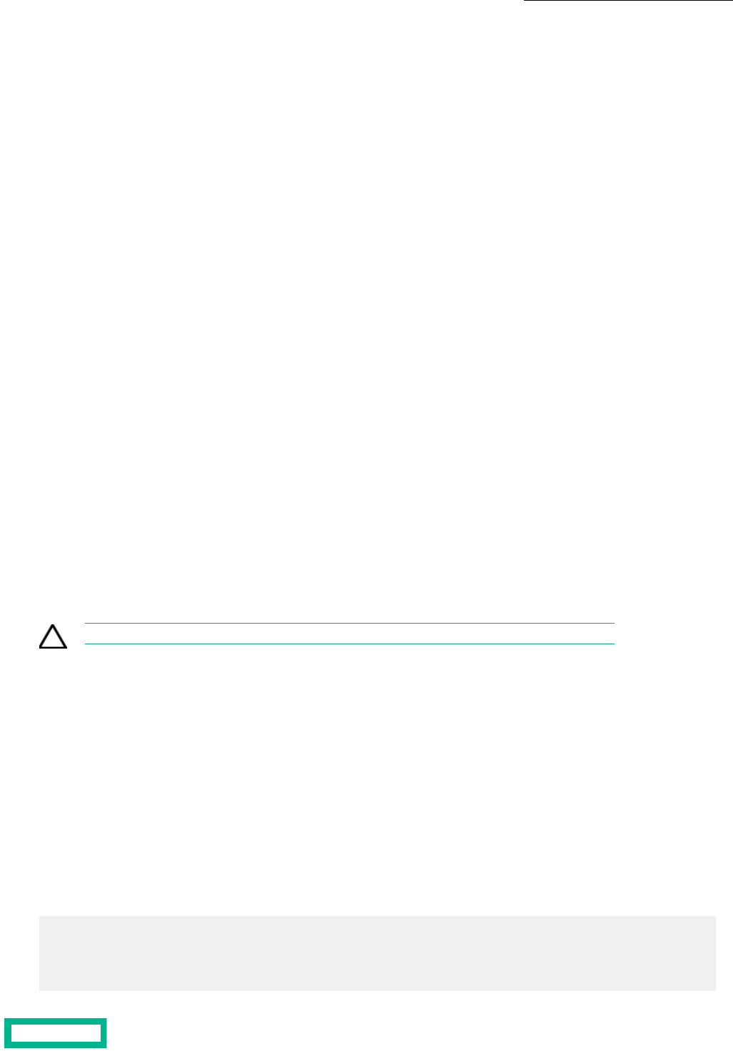
Before you begin
You must have Administrator permission to change the default global security policies for the group.
Procedure
1. Change the maximum number of user settings for a group.
userpolicy --edit --max_sessions num_max_group_sessions
2. Change the number of failed authentication attempts allowed before an account is locked.
userpolicy --edit --allowed_attempts num_allowed_attempts
3. Change the minimum number of characters required for a valid password.
userpolicy --edit --min_length minimum_length
4. Change the minimum number of uppercase characters required for a valid password.
userpolicy --edit --upper num_uppercase_chars
5. Change the minimum number of lowercase characters required for a valid password.
userpolicy --edit --lower num_lowercase_chars
6. Change the minimum number of numerical characters required for a valid password.
userpolicy --edit --digit num_digits
7. Change the minimum number of special characters required for a valid password.
userpolicy --edit --special num_special_chars
8. Change the minimum number of characters that must be different from the previous password.
userpolicy --edit --previous_diff num_chars_change
9. Change the number of times that a password must change before you can reuse an old password.
userpolicy --edit --no_reuse num_no_reuse_last
Modify the Default Inactivity Timeout
By default, users are logged out after a specified amount of time with no activity. You can change the default inactivity timeout
value up to a maximum of 720 minutes (12 hours). The initial default value is 30 minutes.
CAUTION: Before you change the default inactivity timeout interval, consider all security issues.
Before you begin
You must have Administrator permission to change the default inactivity timeout interval for the group.
Procedure
1. Change the global user inactivity timeout (in minutes).
group --edit --inactivity_timeout minutes
2. Verify the new user inactivity timeout
group --info
Example
Configuring the global user inactivity timeout to 240 minutes.
$ group --edit --inactivity_timeout 240
$ group -info
Group name: test-group-1
.
Array Groups 56
Documentation Feedback: [email protected]

.
.
User inactivity timeout: 240 minute(s)
Modify the Default Space Reservation
You can set the default space reservations for new volumes or replicas. If needed, you can specify different settings when
creating volumes. The value must be 0 (thin provisioning) or 100 (thick provisioning).
Procedure
Modify the default volume reserve percentage.
group --edit default_vol_reserve percent
Example
Modifying the default volume reserve percentage.
$ group --edit default_vol_reserve 0
Modify the Date, Time, and Time Zone
The date and time are set when the array is created. However, you can change the date, time, and time zone at any time.
Procedure
1. Modify the time zone for an NTP server
group --edit --ntpserver server
timezone --set zone
2. Modify the time, date, and time zone for an array.
date [--utc] [--edit {hh:mm[ss] |'YYYY-MM-DD hh:mm[:ss]'}]
timezone --set zone
When you use the --utc option, change the Coordinated Universal Time.
Example
Modifying the date and time for an array.
$ date --edit 2015-09-30 12:00:00
Modifying the time zone for an NTP server.
$ group --edit --ntpserver 10.25.55.155
$ timezone --set Europe/Stockholm
Modify DNS Settings
You can use a DNS server to map a hostname to an IP address. The service enables users to type host names that can be
translated into an IP address usable by networking software. You can modify the DNS server settings for the group as needed.
Procedure
Modify the group’s DNS settings.
group --edit [--dnsserver server] [--domainname domain name]
Array Groups 57
Documentation Feedback: [email protected]

Example
Modifying the DNS server hostname or IP address.
$ group --edit --dnsserver 10.25.50.255
Modifying the DNS to allow support to establish a connection to the group to collect diagnostic information.
$ group --edit --support_tunnel yes
Multiprotocol Array Groups
Version 5.1.x and later supports multiprotocol array groups, providing the ability to present volumes to iSCSI or Fibre Channel
(FC) hosts from the same array.
The multi-protocol feature enables you to use both iSCSI and FC protocols simultaneously on a single array or group to access
different volumes.
A volume can be accessed via FC on an array where other volumes are accessed via iSCSI. This feature provides flexibility in
environments with both iSCSI and FC hosts, and it facilitates migrating from one protocol environment to the other.
Note the following prerequisites and limitations for multiprotocol support:
• Every array in the group must have similar hardware capabilities. At least one FC HBA or one iSCSI NIC is required per
controller.
• Protocols are enabled on the entire group. Every array in the group has the same protocols enabled.
• When Peer Persistence is deployed, only one protocol is permitted on the arrays in the group, and both arrays must use
the same protocol.
• A volume can only be accessed via one protocol at a time.
• An initiator group cannot contain a mix of iSCSI and FC hosts.
• SMI-S does not support using multiprotocols.
Note: See the CLI Administration Guide for information about enabling or disabling both iSCSI and FC on an array.
Enable Multiprotocol Access to a Group
Before you begin
• To enable the Fibre Channel protocol, at least one Fibre Channel HBA is required for each controller in the group
• To enable the iSCSI protocol, at least one iSCSI card is required for each controller in the group
• Fibre Channel HBAs for the controllers in each array should use corresponding interfaces, forming an interface pair
• iSCSI cards for the controllers in each array should use corresponding interfaces, forming an interface pair
Procedure
1. Enable the second protocol.
To add Fibre Channel access: group --edit --fc_enabled yes
To add iSCSI access: group --edit --iscsi_enabled yes
2. Verify the protocol state of the group.
group --info
3. Configure the second protocol that you added.
• For Fibre Channel, set up zoning and validate the zones.
• For iSCSI, set up IP addresses and validate the iSCSI network configuration.
See Network Configuration Profiles on page 30.
Array Groups 58
Documentation Feedback: [email protected]

Disable Multiprotocol Access to a Group
Procedure
1. Remove protocol-specific initiator groups for the protocol you want to disable.
initiatorgrp --delete initiatorgrp_name
2. Disable the second protocol.
To disable Fibre Channel access: group --edit --fc_enabled no
To disable iSCSI access: group --edit --iscsi_enabled no
Note: You cannot disable both protocols on a group.
3. Verify the protocol state of the group.
group --info
What to do next
• Remove Fibre Channel HBAs, if desired.
Switch a Volume from iSCSI to Fibre Channel Protocol
A volume can be accessed by only one protocol at a time. You can switch the protocol by which a volume is accessed if both
protocols are enabled for a group. Hosts lose volume access during the switch.
Before you begin
Before changing access to a volume from iSCSI to Fibre Channel protocol:
• You must quiesce any applications on the host that access the volume.
• You must also disconnect the volume from hosts. This ensures that all I/O to the volume has been stopped, thus ensuring
data consistency.
Procedure
1. Remove ACL records from the volume.
vol --removeacl vol_name
Repeat for each ACL and initiator group associated with the volume.
2. Configure Fibre Channel initiator groups and ACLs.
See Fibre Channel Initiator Groups on page 21 and Initiator Group Access Control Lists on page 68.
What to do next
From the hosts, perform a target rescan to be sure the hosts discover the volume.
Switch a Volume from Fibre Channel to iSCSI Protocol
A volume can be accessed by only one protocol at a time. You can switch the protocol by which a volume is accessed if both
protocols are enabled for a group. Hosts lose volume access during the switch.
Before you begin
Before changing access to a volume from Fibre Channel to iSCSI protocol:
• You must quiesce any applications on the host that access the volume.
Array Groups 59
Documentation Feedback: [email protected]

• You must also disconnect the volume from hosts. This ensures that all I/O to the volume has been stopped, thus ensuring
data consistency.
Procedure
1. Remove all Fibre Channel ACL records from the array group.
vol --removeacl vol_name
Repeat for each ACL and initiator group associated with the volume.
2. Configure iSCSI initiator groups and ACLs.
See iSCSI Initiator Groups on page 21 and Initiator Group Access Control Lists on page 68.
3. Verify hosts can discover and log in to iSCSI targets.
What to do next
• From the hosts, perform a target rescan to be sure the hosts discover the volume.
Array Groups 60
Documentation Feedback: [email protected]

Initiator Groups
An initiator is a port on a server or computer that "initiates" a connection with "target" ports on a storage array. It can be an
Ethernet Network Interface Card (NIC) port that initiates a connection over an iSCSI fabric to one or more target ports, or a
Fibre Channel Host Bus Adapter (HBA) port that initiates a connection over a Fibre Channel fabric to one or more target ports.
An initiator group is a collection of either iSCSI initiators or Fibre Channel initiators that are managed as a single unit.
iSCSI Initiator Groups
An iSCSI initiator group is a collection of one or more iSCSI initiators, with each initiator having a unique iSCSI Qualified Name
(IQN) and IP address. Each IQN represents a single Network Interface Card (NIC) port on an iSCSI-based client in the form of
a Windows server, ESXi or Linux host. Configure iSCSI initiator groups on the array; configure client-side iSCSI initiators
according to the vendor's recommendations.
Note: By default, iSCSI volumes deny access to initiators. To allow initiators in an initiator group to access a volume,
you must configure an ACL that includes the desired initiators and attach it to the volume.
Create an iSCSI Initiator Group
Note: When you create an iSCSI initiator group in a group that has multi-protocol access (both iSCSI and Fibre
Channel) configured, you must specify the --access_protocol. If you do not, the access protocol for the initiator is set
to fc by default.
Before you begin
To create an iSCSI initiator group, you must know either the iSCSI Qualified Name (IQN) or IP address, or both, for each initiator
you want to add to the initiator group.
Procedure
1. Create an iSCSI initiator group.
initiatorgrp --create initiatorgrp_name [--description text] [--access_protocol iscsi] [--host_type host_type]
2. Add an initiator to the initiator group.
initiatorgrp --add_initiators initiatorgrp_name [--label label] [--initiator_name iqn] [--ipaddr ipaddr] [--initiator_alias
alias]
Note: If you cannot copy and paste the IQN, type it in very carefully.
3. Add an iSCSI target subnet.
initiatorgrp --add_subnets initiatorgrp_name [--label subnet_label]
4. (Optional) Verify your iSCSI initiator group configuration.
initiatorgrp --info initiatorgrp_name
Example
Creating an iSCSI initiator group, adding initiators and subnets, and displaying the initiator group information.
$ initiatorgrp --create Datamon
$ initiatorgrp --add_initiators Datamon --label Basic --initiator_name iqn.1991-
05.com.microsoft:techops.storage.com --ipaddr 192.0.2.88
Initiator Groups 61

$ initiatorgrp --add_subnets Datamon --label Subnet-198.51.100.0
$ initiatorgrp --info Datamon
Name: Datamon
Description:
Access Protocol: iscsi
Created: Jan 01 2016 12:00:01
Last Configuration Change: Jan 01 2016 12:00:01
Number of Subnets: 1
Subnet Label: Subnet-198.51.100.0
Number of Initiators: 1
Initiator Label: Basic
Initiator Name: iqn.1991-05.com.microsoft:techops.storage.com
Initiator IP Address: 198.0.2.88
Number of Volumes: 2
Volume Name: northVol
Volume Name: southVol
Edit an iSCSI Initiator Group
Procedure
1. Modify the initiator group name, description, or host type.
initiatorgrp --edit initiatorgrp_name [--name new_name] [--description text] [--host_type host_type]
2. Add a subnet to the iSCSI initiator group.
initiatorgrp --add_subnets initiatorgrp_name [ --label subnet_label]
3. Remove a subnet from the iSCSI initiator group.
initiatorgrp --remove_subnets initiatorgrp_name [ --label subnet_label]
4. (Optional) Verify your iSCSI initiator group configuration.
initiatorgrp --info initiatorgrp_name
Example
$ initiatorgrp --edit Datamon
$ initiatorgrp --name Dataman
$ initiatorgrp --description datamanager
$ initiatorgrp --info Dataman
Name: Dataman
Description:
Access Protocol: iscsi
Created: Jan 01 2016 12:00:01
Last Configuration Change: Jan 01 2016 12:00:01
Number of Subnets: 1
Subnet Label: Subnet-198.51.100.0
Number of Initiators: 1
Initiator Label: Basic
Initiator Name: iqn.1991-05.com.microsoft:techops.storage.com
Initiator IP Address: 198.0.2.88
Number of Volumes: 2
Volume Name: northVol
Volume Name: southVol
Initiator Groups 62
Documentation Feedback: [email protected]

Delete an iSCSI Initiator Group
Before you begin
Before you can delete an iSCSI initiator group, you must remove all associated volumes from the initiator group's access control
list(s) (ACLs). For more information, see Remove an Initiator Group ACL from a Volume on page 69.
Procedure
1. Verify that there are no volumes associated with the iSCSI initiator group.
initiatorgrp --info initiatorgrp_name
If any volumes are listed for the initiator group, remove them. For more information, see Remove an Initiator Group ACL
from a Volume on page 69.
2. Delete the initiator group.
initiatorgrp --delete initiatorgrp_name
Example
$ initiatorgrp --info Datamon
Name: Datamon
Description:
Access Protocol: iscsi
Created: Jan 01 2016 12:00:01
Last Configuration Change: Jan 01 2016 12:00:01
Number of Subnets: 1
Subnet Label: Subnet-198.51.100.0
Number of Initiators: 1
Initiator Label: Basic
Initiator Name: iqn.1991-05.com.microsoft:techops.storage.com
Initiator IP Address: 198.0.2.88
Number of Volumes: 0
$ initiatorgrp --delete Datamon
Add an Initiator to an iSCSI Initiator Group
Procedure
1. Add an initiator to the iSCSI initiator group.
initiatorgrp --add_initiators initiatorgrp_name [--label label] [--initiator_name iqn] [--ipaddr ipaddr]
Note: If you cannot copy-and-paste the IQN, type it in very carefully.
2. (Optional) Verify that the initiator has been added to the iSCSI initiator group.
initiatorgrp --info initiatorgrp_name
Example
Adding an initiator to the initiator group, and confirming the results.
$ initiatorgrp --add_initiators Datamon --label Intermediate --initiator_name
iqn.1991-06.com.microsoft:techops.storage.com --ipaddr 192.0.2.90
$ initiatorgrp --info Datamon
Name: Datamon
Description:
Access Protocol: iscsi
Created: Jan 01 2016 12:05:01
Last Configuration Change: Jan 01 2016 12:05:01
Number of Subnets: 1
Initiator Groups 63
Documentation Feedback: [email protected]

Subnet Label: Subnet-198.51.100.0
Number of Initiators: 2
Initiator Label: Basic
Initiator Name: iqn.1991-05.com.microsoft:techops.storage.com
Initiator IP Address: 198.0.2.88
Initiator Label: Intermediate
Initiator Name: iqn.1991-06.com.microsoft:techops.storage.com
Initiator IP Address: 198.0.2.90
Number of Volumes: 4
Volume Name: northVol
Volume Name: southVol
Volume Name: eastVol
Volume Name: westVol
Remove an Initiator from an iSCSI Initiator Group
Procedure
1. Remove an initiator from the iSCSI initiator group.
initiatorgrp --remove_initiator initiatorgrp_name [--label label]
2. (Optional) Verify that the initiator has been removed from the iSCSI initiator group.
initiatorgrp --info initiatorgrp_name
Example
$ initiatorgrp --remove_initiator GST-Test --label Basic
$ initiatorgrp --info GST-Test
Name: GST-Test
Description:
Host Type: auto
Access Protocol: iscsi
Application identifier:
Created: Sep 4 2018 14:01:50
Last configuration change: Oct 1 2020 13:46:08
Number of Subnets: All
Number of Initiators: 0
Number of Volumes: 2
Volume Name: Vol2ForTesting
Volume Name: bks-volume
Fibre Channel Initiator Groups
A Fibre Channel initiator group is a collection of one or more initiators, with each initiator having a unique World Wide Port
Name (WWPN). Each WWPN represents a single Host Bus Adapter (HBA) port on a Fibre Channel-based client in the form of
a Windows server, ESXi or Linux host. Configure Fibre Channel initiator groups on the array; configure client-side Fibre Channel
initiators according to the vendor's recommendations.
Note: By default, Fibre Channel volumes deny access to initiators. To allow initiators in an initiator group to access
a volume, you must configure an ACL that includes the desired initiators and attach it to the volume.
Create a Fibre Channel Initiator Group
Note: When you create a Fibre Channel initiator group in a group that has multiprotocol access (both Fibre Channel
and iSCSI) configured, you are not required to specify the --access_protocol, because it will be set to fc by default. It
is included in the first step, below, for completeness.
Initiator Groups 64
Documentation Feedback: [email protected]

Before you begin
To create an Fibre Channel initiator group, you must know the Fibre Channel World Wide Port Name (WWPN) for each initiator
being added to the group.
Procedure
1. Create a Fibre Channel initiator group.
initiatorgrp --create initiatorgrp_name [--description text] [--access_protocol fc] [--host_type host_type]
Note: The --host_type option is only needed when creating an initiator group for HP-UX systems. Specify hpux
as the host_type sub-option when creating an initiator group in HP-UX.
2. Add an initiator.
initiatorgrp --add_initiators initiatorgrp_name [--label label] [--initiator_alias initiator_alias] --wwpn wwpn [--force]
Use the --force option to forcibly add a Fibre Channel initiator to the specified initiator group by updating or removing
conflicting Fibre Channel initiator aliases.
Note: A WWPN is 16 hexadecimal characters (case insensitive) in XX:XX:XX:XX:XX:XX:XX:XX or
XXXXXXXXXXXXXXXX format. If you cannot copy-and-paste the WWPN, type it in very carefully.
3. (Optional) Verify your Fibre Channel initiator group.
initiatorgrp --info initiatorgrp_name
Example
$ initiatorgrp --create Datamon
$ initiatorgrp --add_initiators Datamon --label client1 --wwpn
10:20:00:a0:fa:63:c2:61
$ initiatorgrp --info Datamon
Name: Datamon
Description:
Access Protocol: fc
Created: Jan 01 2016 12:00:01
Last Configuration Change: Jan 01 2016 12:00:01
Number of Initiators: 1
Initiator: client1 (10:20:00:a0:fa:63:c2:61)
Number of Volumes: 1
Volume Name: northVol
LUN: 0
Add a Target Driven Zone Port to an Initiator Group
Procedure
Add a Target Driven Zone port to an initiator group.
initiatorgrp --add_tdz_ports initiatorgrp_name --interface_name interface_name --array {name | serial}
Remove a Target Driven Zone Port from an Initiator Group
Procedure
Remove a Target Driven Zone port to an initiator group.
initiatorgrp--remove_tdz_ports initiatorgrp_name--interface_name interface_name--array {name | serial}
Initiator Groups 65
Documentation Feedback: [email protected]

What to do next
Edit a Fibre Channel Initiator Group
Procedure
1. Change the initiator group name, description, or host type.
initiatorgrp --edit initiatorgrp_name [--name new_name] [--description text] [--host_type host_type]
Note: The --host_type option is only needed when editing an initiator group for HP-UX systems. Specify hpux
as the host_type sub-option when editing an initiator group in HP-UX.
2. Add an initiator.
initiatorgrp --add_initiators initiatorgroup_name [--label label] [--initiator_alias initiator_alias] --wwpn WWPN
Example:
Note: A WWPN is 16 hexadecimal characters (case insensitive) in XX:XX:XX:XX:XX:XX:XX:XX or
XXXXXXXXXXXXXXXX format. If you cannot copy-and-paste the WWPN, type it in very carefully.
3. (Optional) Verify your Fibre Channel initiator group configuration.
initiatorgrp --info initiatorgrp_name
Example
$ initiatorgrp --edit Datamon
$ initiatorgrp --add_initiators Datamon --label client1 --wwpn
10:20:00:a0:fa:63:c2:61
$ initiatorgrp --info Datamon
Name: Datamon
Description:
Access Protocol: fc
Created: Jan 01 2016 12:00:01
Last Configuration Change: Jan 01 2016 12:00:01
Number of Initiators: 1
Initiator: client1 (10:20:00:a0:fa:63:c2:61)
Number of Volumes: 1
Volume Name: northVol
LUN: 0
Delete a Fibre Channel Initiator Group
Before you begin
Before you can delete a Fibre Channel initiator group, you must remove all associated volumes from the initiator group's access
control list(s) (ACLs). For more information, see Remove an Initiator Group ACL from a Volume on page 69.
Procedure
1. Verify that there are no volumes associated with the Fibre Channel initiator group.
initiatorgrp --info initiatorgrp_name
If any volumes are listed for the initiator group, remove them. For more information, see Remove an Initiator Group ACL
from a Volume on page 69.
2. Delete the initiator group.
initiatorgrp --remove initiatorgrp_name
Initiator Groups 66
Documentation Feedback: [email protected]

Example
$ initiatorgrp --info Datamon
Name: Datamon
Description:
Access Protocol: fc
Created: Jan 01 2016 12:00:01
Last Configuration Change: Jan 01 2016 12:00:01
Number of Initiators: 1
Initiator: client1 (10:20:00:a0:fa:63:c2:61)
Number of Volumes: 0
$ initiatorgrp --delete Datamon
Add an Initiator to a Fibre Channel Initiator Group
Procedure
1. Add an initiator.
initiatorgrp --add_initiators initiatorgrp_name [--label label] [--initiator_alias ialias] --wwpn wwpn [--force]
Use the --force option to forcibly add a Fibre Channel initiator to the initiator group by updating or removing conflicting
Fibre Channel initiator aliases.
Note: A WWPN is 16 hexadecimal characters (case insensitive) in XX:XX:XX:XX:XX:XX:XX:XX or
XXXXXXXXXXXXXXXX format. If you cannot copy-and-paste the WWPN, type it very carefully.
2. (Optional) Verify that the initiator has been added to the Fibre Channel initiator group.
initiatorgrp --info initiatorgrp_name
Example
$ initiatorgrp --create Datamon
$ initiatorgrp --add_initiators Datamon --label client1 --wwpn
10:20:00:a0:fa:63:c2:61
$ initiatorgrp --info Datamon
Name: Datamon
Description:
Access Protocol: fc
Created: Jan 01 2016 12:00:01
Last Configuration Change: Jan 01 2016 12:00:01
Number of Initiators: 1
Initiator: client1 (10:20:00:a0:fa:63:c2:61)
Number of Volumes: 1
Volume Name: northVol
LUN: 0
Remove an Initiator from a Fibre Channel Initiator Group
Procedure
1. Remove an initiator from the FC initiator group.
initiatorgrp --remove_initiators initiator_group_name [--label initiator_label] [--initiator_alias alias] [ --wwpn wwpn]
Note: If you cannot copy-and-paste the WWPN, type it very carefully.
Important: If both the --initiator_alias and --wwpn options are provided, they must be synchronized. If they are
not, the initiator will not be removed from the initiator group.
Initiator Groups 67
Documentation Feedback: [email protected]

2. (Optional) Verify that the initiator has been removed from the Fibre Channel initiator group.
initiatorgrp --info initiator_group_name
Example
$ initiatorgrp --create Datamon
$ initiatorgrp --add_initiators Datamon --label client1 --wwpn
10:20:00:a0:fa:63:c2:61
$ initiatorgrp --info Datamon
Name: Datamon
Description:
Access Protocol: fc
Created: Jan 01 2016 12:00:01
Last Configuration Change: Jan 01 2016 12:00:01
Number of Initiators: 1
Initiator: client1 (10:20:00:a0:fa:63:c2:61)
Number of Volumes: 1
Volume Name: northVol
LUN: 0
Initiator Group Access Control Lists
All initiators in an initiator group are granted access to a volume when the access-control list (ACL) for an initiator group is
added to the volume. An ACL can be added to multiple volumes, granting the initiators in the group access to those volumes.
When you create or edit a volume, you can add one or more initiator group ACLs to it.
Note: If you do not add any ACLs to a volume, no initiators will be able to connect to the volume.
Add an Initiator Group ACL to a Volume
Procedure
1. Add an initiator group access control list (ACL) to a volume.
vol --addacl vol_name [--apply_acl_to {volume | snapshot | both} ] [--initiatorgrp group_name] [--lun lun] [--pool
pool_name]
Note: The --pool option is required if the volume name is not unique within the group.
2. Verify that the initiator group ACL has been added to the volume.
initiatorgrp --info group_name
Example
Adding an initiator group ACL to a volume.
$ vol --addacl test2 --apply_acl_to volume --initiatorgrp Datamon
$ initiatorgrp --info Datamon
Name: Datamon
Description:
Access Protocol: fc
Application identifier:
Created: Feb 10 2016 12:00:01
Last configuration change: Jan 01 2016 12:00:01
Number of Initiators: 3
Initiator: winInit2 (12:34:56:78:90:12:34:52)
Initiator: esxiInit22 (12:34:56:78:90:12:34:54)
Initiator: linuxInit78 (12:34:56:78:90:12:34:56)
Initiator Groups 68
Documentation Feedback: [email protected]

Number of Volumes: 2
Volume Name: test1
LUN: 0
Volume Name: test2
LUN: 1
Remove an Initiator Group ACL from a Volume
Procedure
1. Remove a volume from an iSCSI Initiator Group Access Control List (ACL)
vol --removeacl [volume_name] --apply_acl_to [volume snapshot | both] --initiatorgrp [group_name] [--pool pool_name]
Note: The --pool option is required if the volume name is not unique within the group.
2. Verify that the initiator group ACL has been removed from the volume.
initiatorgrp --info group_name
Example
$ vol --removeacl test1 --apply_acl_to volume --initiatorgrp Datamon
$ initiatorgrp --info Datamon
Name: Datamon
Description:
Access Protocol: fc
Application identifier:
Created: Feb 10 2016 12:00:01
Last configuration change: Jan 01 2016 12:00:01
Number of Initiators: 3
Initiator: winInit2 (12:34:56:78:90:12:34:52)
Initiator: esxiInit22 (12:34:56:78:90:12:34:54)
Initiator: linuxInit78 (12:34:56:78:90:12:34:56)
Number of Volumes: 1
Volume Name: test2
LUN: 1
Initiator Groups 69
Documentation Feedback: [email protected]

Volumes
Volumes are the basic storage units from which the total capacity of an array is apportioned. The number of volumes per array
depends on how the storage is allocated.
Hosts connect to volumes using iSCSI or Fibre Channel. A volume appears to a host as a single disk drive, which can be used
as a file system, a raw disk, or a virtual disk.
When you delete a volume, the snapshots that are associated with that volume are also deleted. If the volume has online
snapshots, they must be taken offline before you can delete them.
Clones, Replicas, and Snapshots
The array OS lets you manage the objects in a storage system: volumes and their associated clones, replicas, and snapshots.
Clones are writable, highly space-efficient copies of volumes which you can create from snapshots. When you create a clone
from a snapshot, you create a new volume with a new name and iSCSI or Fibre Channel target with the same settings. Clones
share identical blocks and are often used to test applications before putting them into production.
Replicas are copies of volumes stored on a different array, called a replication partner. Replicas are most often used for disaster
recovery. For more information about replicas and replication, see Replication on page 119.
Snapshots are point-in-time copies of volumes. Snapshots are often used as backups, and to preserve the state of volumes
at specific points. By creating a clone from a snapshot, snapshots can also be used as starting points to which applications
can write and read data. For more information about snapshots, see Snapshots on page 95.
Logical versus Physical Space
When working with volumes, it is important to understand the difference between logical space and physical space.
Physical storage resources are aggregated into storage pools from which the logical storage is created. It allows you to have
a logical space for data storage on physical storage disks by mapping space to the physical location. Physical space is the
actual space on the hardware that is used.
Logical space is space that the system manages, such as the volume size. In this case, the volume size is not necessarily the
actual amount of space on a physical disk, but the amount of space defined for a volume, which may span multiple physical
disks.
Space Management
The array OS has built-in capacity saving mechanisms such as inline compression and thin provisioning. The following
considerations help you plan your space configuration for volumes and snapshots.
The simplest form of space management is to not use reserves at all. This means that there is no dedicated (prereserved)
space per volume taken from the general storage pool, so all volumes can consume what they need as it is needed. This method
requires that you monitor space usage to ensure that there is always space available.
However, for critical volumes, such as those hosting business-critical data, it may be more important for you to reserve space
to ensure that the volume will always have enough. Reserved space is immediately taken from the storage pool.
When you create a volume, you define a certain amount of space for that volume. The volume space is the size that is reported
to your application.
Volumes 70
Documentation Feedback: [email protected]

Volume Reserve
Volume reserve is guaranteed physical space that is reserved for a volume. Reserved space is set aside for the volume and is
immediately withdrawn from the general storage pool. Set the volume reserve to Thin Provisioning (no physical space is
reserved) or Thick Provisioning (the entire physical space is reserved). As new data is written to a thickly provisioned volume,
free space within the volume reserve decreases.
One consideration when setting volume sizes and reserves is the level of compression you get for a particular application or
data set. For example, most volumes should see 50-75% compression, so a volume reserve of 10 GB will be able to store far
more than the actual 10 GB space if it were uncompressed. In other words, 10 GB space of application data will only use
between 2.5 GB and 5 GB when compressed.
Thin Provisioning
Thin provisioning is a storage virtualization technology that uses physical storage only when data is written instead of traditional
provisioning, which reserves all the capacity up-front when an application is configured. This method addresses over-provisioning
and its associated costs. Frequently, volumes reserve excessive space against expected growth. Often this growth does not
materialize, or materializes much later than expected. With thin provisioning, you create volumes and assign them to servers
and applications, but the physical resources are only assigned when the data is written. Physical storage that is not being used
remains available to other volumes. No unnecessary storage is reserved for use by any single application.
For example, like most SANs, your array must support several applications. Projections show that eventually the total storage
needed by all applications will reach 3 TB. However, for the first few quarters of the year, these applications should only use
about 300 GB. Instead of creating the volumes using the total 3 TB that you expect to need, with thin provisioning you can
create three 1 TB volumes, but set the reserve to only 150 GB for each volume. When you factor in compression savings, the
applications should not use the full 3 TB until the next purchasing window, minimizing the cost of buying more capacity until
it is needed.
Volume Usage Limits
Volume usage limits determine how much of a volume can be consumed before an alert is sent to the administrator. When
the usage limit is reached, the performance policy associated with the volume determines the next action (for example, whether
to make the volume read-only or take the volume offline). An alert is also sent.
Thickly-provisioned volumes have a default volume limit of 100 percent. For thinly-provisioned volumes, you can set the
volume limit to a value between 0 and 100 percent. Some applications do not tolerate changes to volume sizes. Limits address
this issue. Volume limits let you set a limit but leave room in case more space is needed.
For example, if you have an application that you do not want to fill all the space on the volume before more space is available
for expansion, set a limit for the volume. You now have a safety factor, and when the limit is met, you can reset the limit, giving
more space to the application. You can then plan for further expansion if necessary.
If the volume is approaching the limit, an event is logged. If enforcement is enabled, the administrator can access the system
log to determine what follow-up actions to take, such as preventing the user from accessing more disk space or allocating
additional disk space to the user.
Note: Volume usage limit must be greater than or equal to the volume reserve.
A Note on Defragmentation
Do not defragment volumes on an array. The value of defragmentation is mainly on a local physical disk to keep files contiguous
so the disk heads do not require unnecessary physical seeks across the platters, and slow down file I/O.
There is no such value about the effectiveness of this in a networked iSCSI environment, especially where files are stored on
storage devices that have their own layers of virtualization.
Defragmenting files in a storage array environment results in changed blocks, even though the files did not change, and can
have unnecessary impacts, such as snapshots being larger than they should.
Volumes 71
Documentation Feedback: [email protected]

Cloning Space Considerations
Clones are space-efficient copies of a volume that can be used independently of the source volume. When created, they have
the same settings as the volume from which they were created. Clones share blocks that are identical with the source volume,
and only begin to use space when changes are made.
HPE recommends that you lower the reserve settings for clones. When determining the reserve settings, factors to consider
include how long-lived the clone will be and how much the clone will vary from its source. For example, the reserve settings
may not need to be very high if the clone is being run to test a new application against, will not be changed much, and will be
deleted after the testing is complete.
Note: You cannot delete the source volume of a clone unless you first delete the clone.
Protecting Data Using Snapshots
Snapshots ensure that data stored in volumes is always recoverable.
Note: If a volume is deleted, all associated snapshots are also permanently deleted.
Merging primary and backup storage makes snapshots an efficient method to protect data. Because no data needs to be
copied outside the array, snapshots can be created and used to restore data almost instantaneously.
You can restore a volume from either the local recovery point or the remote recovery point. The local recovery point is the
last local snapshot taken for the volume. The remote recovery point is the last snapshot taken through replication.
Because snapshots are part of the converged storage and backup, and because they are so efficient, consider the implications
when creating snapshots. For some applications, the amount of storage used for snapshots may equal or exceed the storage
needed for the source volume.
Even if you plan to manually take snapshots of volumes or use a third-party program to create backups, create a volume
collection without schedules for volumes that are being manually snapshotted.
Create a Volume
Volumes are also referred to as logical units (LUNs). They are the building blocks of any storage system. A host connects to
the volume via iSCSI or Fibre Channel, and the volume appears to the host as a single disk drive, which can be used as a file
system, a raw disk, or a virtual disk.
Note:
The --chapuser and --multi_initiator options for the vol command apply only to iSCSI volumes.
The --cached_pinned and --dedupe_enabled options cannot both be enabled for the same volume created on a hybrid
flash array that supports deduplication.
Procedure
1. Create a volume.
vol --create name --size mebibytes [--description text] [--perfpolicy name] [--iops_limit iops] [--mbps_limit mbps]
[--cached_pinned {yes |no}] [--thinly_provisioned {yes | no}] [--limit percent] [--start_offline] [--apply_acl_to {volume
|snapshot |both}] [--chapuser user_name ] [--initiatorgrp group name] [--lun lun ] [--multi_initiator {yes |no}] [--pool
pool_name ] [--folder folder_name ] [--agent_type {smis |none}] [--encryption_cypher {aes-256-xts |none}]
[--dedupe_enabled {yes |no}] [--iscsi_target_scope {volume | group}]
Be aware of the following when creating a volume:
Volumes 72
Documentation Feedback: [email protected]

• If you set --dedupe_enabled to yes, you cannot set --thinly_provisioned to no at the same time. A volume with
deduplication enabled is thinly provisioned by default.
Once deduplication is enabled for a volume, the volume reserve and application category cannot be changed, even if
deduplication is later disabled.
• Volumes created in a group that is configured for iSCSI Group Scope Target (GST) inherit the --iscsi_target_scope of
group. You must specify the --iscsi_target_scope as volume if you want the volume to be a volume scoped target (VST).
• If you set --thin_provisioned to yes, you must enter a volume --limit as a numeric value between 0 and 100 percent.
The volume limit is a percentage of the volume reserve.
Note: The volume will be taken offline after the volume limit is reached.
• If the volume description contains spaces, enclose all characters and spaces of the text variable in quotation marks. If
you do not, the volume description will be truncated at the first space.
2. (Optional) Add an ACL to grant access to the volume to an initiator group.
vol --addacl test1 --initiatorgrp group_name
Note:
See Create an iSCSI Initiator Group on page 61 for the procedure to create an iSCSI initiator group.
See Create a Fibre Channel Initiator Group on page 64 for the procedure to create a Fibre Channel initiator group.
See vol in the Command Reference for more detail about the vol command.
Example
Creating a volume named test1, specifying its size and thin provisioning.
$ vol --create test1 --size 10000 --thinly_provisioned yes --limit 95
Creating a volume named test1, specifying its size, thin provisioning, and setting the encryption cypher to AES 256 XTS.
$ vol --create test1 --size 10000 --thinly_provisioned yes --limit 95 --encryp►
tion aes-256-xts
Creating a volume named test1, specifying its size, thin provisioning, and providing a description.
$ vol --create test1 --size 10000 --thinly_provisioned yes --limit 95 --descrip►
tion "for all departments"
Creating a volume named test1, specifying its size, thin provisioning, applying the performance policy Policy1, and setting the
cache pinned option to yes.
$ vol --create test1 --size 10000 --thinly_provisioned yes --limit 95 --perf►
policy Policy1 --cached_pinned yes
Adding an ACL to grant access to the volume test1 to the initiator group Dataman.
$ vol --addacl test1 --initiatorgrp Dataman
What to do next
• Configure the iSCSI or Fibre Channel connections on your volumes to connect to the group leader array.
• Configure the iSCSI or Fibre Channel connections for your server or host to access those volumes.
• Configure your client initiator according to the vendor's recommendations.
Volumes 73
Documentation Feedback: [email protected]

Edit a Volume
You can modify most volume configuration options, such as access restrictions, performance policy, and volume collection
assignment after you have created the volume.
Note: If deduplication was enabled when the volume was created, the volume reserve and application category cannot
be changed.
Before you begin
Before you rename a volume, you must take it offline.
Procedure
1. Take the volume offline.
vol --offline vol_name
2. Make the required changes.
vol --edit vol_name [--name new_name] [--size mebibytes] [--description text] [--perfpolicy name] [--cached_pinned
{yes |no}] [--readonly {yes | no}] [--iops_limit iops] [--mbps_limit mbps] [--dedupe_enabled {yes| no}]
[--thinly_provisioned {yes | no}] [--force] [--limit percent] [--multi_initiator {yes | no}] [--agent_type {none | smis}]
[--iscsi_target_scope volume | group}] [--pool pool_name]
Important:
If the volume description contains spaces, enclose all characters and spaces of the text variable in quotation marks.
If you do not, the volume description will be truncated at the first space.
See vol in the Command Reference for more information about this command.
Note: If you are editing a volume with reserve, and you enable deduplication, thin provisioning is enabled by
default.
3. Set the updated volume to online.
--online vol_name
4. (Optional) Add an ACL to grant access to the volume to an initiator group.
vol --addacl test1 --initiatorgrp group_name
Note:
See Create an iSCSI Initiator Group on page 61 for the procedure to create an iSCSI initiator group.
See Create a Fibre Channel Initiator Group on page 64 for the procedure to create a Fibre Channel initiator group.
Example
Taking the volume test1 offline and changing its name to test2.
$ vol --offline test1
$ vol --edit test1 --name test2
Setting the volume test2 online.
$ vol test2 --online
Volumes 74
Documentation Feedback: [email protected]

Editing the volume test2, changing its size and description.
$ vol --edit test2 --size 20000 --description "for finance department"
Editing the volume test2, changing the performance policy, and setting the cache pinning option
$ vol --edit test2 --perfpolicy Policy3 --cached_pinned no
Adding an ACL to grant access to the volume test2 to the initiator group Dataman.
$ vol --addacl test2 --initiatorgrp Dataman
Change a Volume's State
Taking a volume offline makes that volume unavailable to initiators. When you set a volume to offline, all current connections
are closed.
Procedure
Set a volume offline or online, depending on its current state. Use one of the following commands:
• vol --offline vol_name
• vol --offline vol_name
Example
Setting a volume offline:
$ vol --offline MyVolume
Setting a volume online:
$ vol --online MyVolume
Clone a Volume from a Snapshot
Clones of snapshots are useful for restoring individual files instead of a complete volume.
Cloning a volume (via a snapshot) creates a new volume with a new name, but keeps all other settings of the original, including
the data at the time the snapshot was taken.
When you clone a volume, settings such as reported size, reserve size, and security are cloned. Clones are set online by default,
and are writable. The clone consumes space from the same space as the original volume.
Note: When a volume configured for synchronous replication is cloned, the cloned volume will not automatically be
configured for synchronous replication.
Procedure
Clone a volume.
vol --clone vol_name --snapname snap_name --clonename clone_name
Example
Creating the clone Clonetest1 from volume Test1 and snapshot Snap30.
$ vol --clone Test1 --snapname Snap30 --clonename Clonetest1
Volumes 75
Documentation Feedback: [email protected]

What to do next
Volume collections are not automatically assigned to the clone. Edit the clone to assign it to the desired volume collection to
ensure that snapshots and replicas will be made according to the desired schedule.
Restore a Volume from a Snapshot
You can restore a volume from one of its snapshots. A snapshot is automatically taken of the existing state before the volume
is restored, even if third-party software is used.
Note: When restoring a volume, it is recommended that you unmount the volume from the host before putting the
restored snapshot online. Restoring a volume without stopping all host access can cause data corruption and system
errors.
Procedure
1. Set the volume to be restored offline.
vol --offline vol-name
2. Restore the volume from the specific snapshot you need to restore the data.
vol --restore vol-name --snapname name
3. Set the restored volume online.
vol --online vol_name
Example
Restoring the volume nimVol3 from the snapshot nimSnap12:
$ vol --offline nimVol3
$ vol --restore nimVol3 --snapname nimSnap12
$ vol --online nimVol3
Delete a Volume
Deleting a volume also deletes any snapshots of the volume. Because clones share the original data with the source volume,
you cannot delete a volume that has a clone.
CAUTION: All data stored on the volume will be destroyed.
Procedure
1. Take the volume offline.
vol --offline vol_name
2. Disassociate the volume from any volume collections.
vol --dissoc vol_name
Note: This step is mandatory for all volumes, including standalone volumes.
3. Delete the volume.
vol --delete vol_name
Volumes 76
Documentation Feedback: [email protected]

Volume Pinning
Note: Volume pinning is not supported with synchronous replication.
Volume pinning allows you to keep active blocks of a volume in the cache, as well as writing them to disk. This provides a
100% cache hit rate for specific volumes (for example, volumes dedicated to critical applications), and delivers the response
times of an all-flash storage system.
A volume is "pinned" when the entire active volume is placed in cache; associated snapshot (inactive) blocks are not pinned.
All incoming data after that point is pinned. The number of volumes that can be pinned is limited by the size of the volumes
and amount of available cache. However, only one volume in a volume family (a volume and the associated snapshots and
clones) can be pinned.
Note: Pinning a volume may affect the cache hit rate of other volumes. It is a best practice to avoid unnecessary
cache pinning.
Pinnable Flash Capacity
Only a portion of the array's total flash capacity can be used for pinning. The amount of pinnable capacity is determined by
the amount of usable cache in the system and the amount of usable disk capacity in the system. The array OS performs these
calculations.
The formula for determining pinnable capacity depends on whether you are using a deduplication:
• A hybrid array without deduplication:
pinnable capacity = 66% * (usable cache capacity - (4% * usable disk capacity))
For example, an array without deduplication enabled that has a usable disk capacity of 100 TB and a total flash capacity
of 12 TB, the total pinnable capacity of the array is 66% of ((12 TB - (4% * 100 TB)) = 5.28 TB.
• A hybrid array with deduplication enabled:
pinnable capacity = 66% * (usable cache capacity - (4% * usable disk capacity) – (4% * maximum-enabled deduplication
capacity))
For striped pools, the pinnable capacity is
(minimum value of (pinnable capacity/usable disk capacity) on any individual array) * (total usable disk capacity across
all arrays in the stripe)
If you are unable to pin a volume, you may need to adjust the flash capacity. For more information, see Unable to Pin a Volume
on page 79.
Volume Pinning Caveats
Note: Volume pinning is not supported with synchronous replication.
When performing certain operations related to volume pinning, keep these caveats in mind.
Table 8: Volume Pinning Caveats
SolutionCondition
To be able to pin the volume, the cache must be enabled on the performance policy for the
volume.
Volume Pinning Enablement
When changing a pinned volume's space limits, the amount of cache reserved for the volume
will also change. You will not be able to pin volumes until sufficient cache is available.
Limit and Volume Size
Changes
Volumes 77
Documentation Feedback: [email protected]
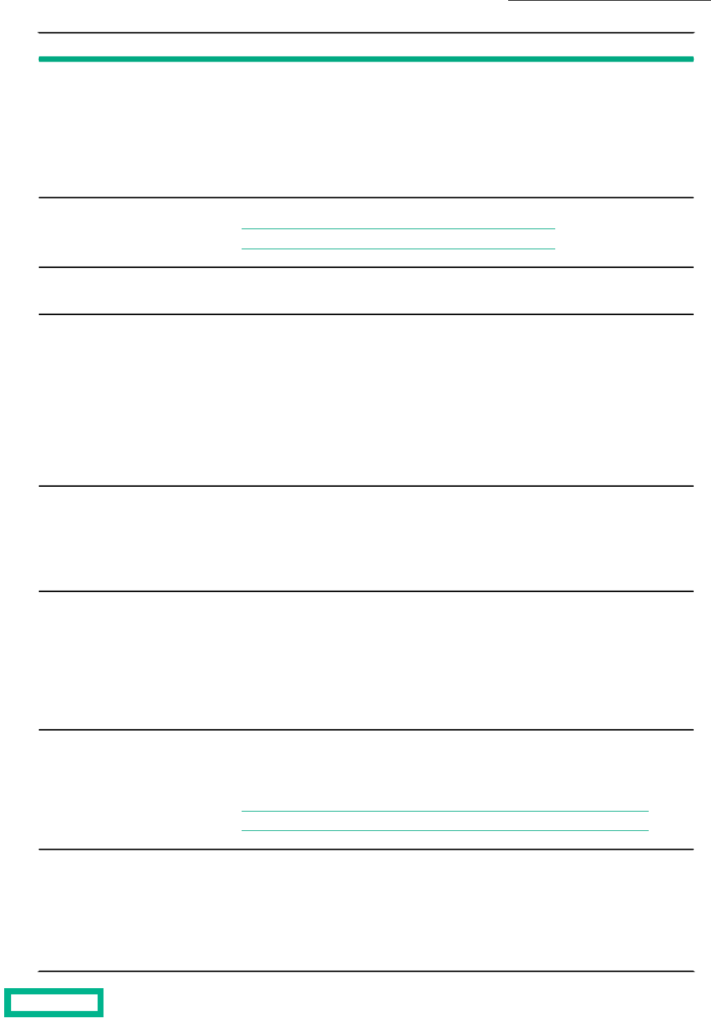
SolutionCondition
When moving a volume, the pinnable capacity on the destination array or pool must be sufficient
to pin the moving volume. Before moving the volume, ensure there is enough cache on the
destination array or pool. The cache usage on the source will be freed on the completion of the
move.
If you attempt to pin a volume during a volume move, pinning will not be guaranteed until a
scan has finished on the destination. This could take some time (up to several hours) depending
on how much content is in the volume, and how much other activity there is.
Moving a Volume
If you replicate a pinned volume, the volume will not be pinned downstream.
Note: You cannot synchronously replicate a pinned volume.
Replicating a Volume Using
Snapshot Replication
When adding a shelf to an array, if the total of the new pinnable capacity is less than the size
of the pinned volumes, the shelf activation will fail.
Adding Shelf Capacity
When an SSD fails or is removed, if the amount of pinnable capacity is less than the current
size of the pinned volumes, then all volumes may become unpinned, because there is not enough
free cache to pin the blocks. A message is displayed recommending that you consider adding
capacity or unpinning some volumes to restore performance to cache pinned volumes. If the
SSD is replaced with one of the same capacity, volume pinning continues normally. If the SSD
is replaced with one of a different capacity, the amount of pinnable cache is recalculated.
One consolidated alert is sent for all volumes when the free usable cache drops below the ac-
ceptable level, and another alert is sent once the free usable cache returns to an acceptable
level for the rescan to be completed.
Failed, Removed, or Upgrad-
ed SSD
If you are using the Edit function to specify that a volume is to be pinned, this initiates a scan
of the volume. Pinning will not be guaranteed until the scan of the volume is finished. This
could take some time (up to several hours) depending on how much content is in the volume,
and how much other activity there is.
Alerts are sent both when pinning begins and ends, on a per-volume basis.
Pinning an Existing Volume
If you have performed a bin migration (for space balancing, for example), or if you attempt to
pin a volume during a bin migration or pool merge, pinning will not be guaranteed until a rescan
has been completed on the bin's new destination. This could take some time (up to several
hours) depending on how much content is in the volume, and how much other activity there
is.
For a bin migration, one consolidated alert is sent for all volumes once the rescan is finished.
For a pool merge, one consolidated alert is sent for all the volumes before and after the merge.
Performing a Bin Migration
or Pool Merge
If you want to do a volume snapshot restore (unpin an old volume and pin a new volume) to
re-establish the heat map (cache hit information), pinning will not be guaranteed until a scan
of the new tip has finished. This could take some time (up to several hours) depending on how
much content is in the volume, and how much other activity there is.
Note: A snapshot restore can only be performed after unpinning the volume.
Performing a Volume Snap-
shot Restore
In case of a software upgrade, pinning will not be guaranteed until a rescan is performed to
determine whether any blocks that were in memory were evicted as a result of the software
upgrade. This could take some time (up to several hours) depending on how much content is
in the volume, and how much other activity there is.
One consolidated alert is sent for all the volumes regarding possible loss of pinning, and another
alert is sent once the rescan has completed.
Performing a Software Up-
grade
Volumes 78
Documentation Feedback: [email protected]

SolutionCondition
In the case of an unmanaged shutdown (where a few segments of pinned data are not flushed
and can show up as cache misses), pinning will not be guaranteed until a rescan of the system
is finished.
One consolidated alert is sent for all the volumes before and after the rescan.
Unmanaged Shutdown
Demoting a pinned volume will automatically unpin the volume. The volume can be pinned
again after promoting it.
Volume Promotion/Demo-
tion
Pinning a Volume Created with a Previous Release
When trying to pin an existing volume that was created before version 2.1, the volume will not be pinned. This is because the
current array caching technology is not compatible with volumes created before Version 2.1.
To successfully pin a volume that was created before array OS version 2.1, you must upgrade the array to 2.1 or higher, and
wait for the cache to age out. As the cache ages out under the new array OS, it is rebuilt with the latest caching technology.
Once the cache ages out completely, you can safely pin the volume. A two-month cache aging period is generally sufficient.
However, if you want to obtain the exact cache aging period for your volume, contact support.
Unable to Pin a Volume
If you try to pin a volume and receive a "cache capacity exceeds available capacity" message, you have insufficient usable
cache to pin the volume. There are two options:
• Use another pool - you can use the array OS to display a list of other pools with sufficient cache. You have the option to
switch your volume to that pool.
• Unpin other pinned volumes - you can view the pinning capacity of other volumes by hovering over their names listed on
the Caching dialog. A tooltip is displayed with the pinning capacity information for that volume. If your volume is already
pinned but you want to free more usable cache, you can use the Caching facet on the volume's information page to view
a list of pinned volumes.
Pin a Volume
Note: Before you pin a volume, the performance policy associated with that volume must have caching enabled.
Procedure
Pin the volume.
vol --edit volume_name --cache_pinned yes
If the volume can be pinned, you will see additional capacity information for that volume. If the volume cannot be pinned,
you may see a "cache capacity exceeds available capacity" message.
Example
Pinning a volume:
vol --edit volume1 --cache_pinned yes
Unpin a Volume
You can unpin an existing volume using the commands below.
Procedure
Unpin a volume.
vol --edit volume_name --cache_pinned no
Volumes 79
Documentation Feedback: [email protected]

When a volume is unpinned, the blocks are given a cache performance policy of Normal.
Example
Unpinning a volume:
vol --edit volume1 --cache_pinned no
Performance Policies
Performance policies define how data is stored on the array to achieve optimal performance for a specific application. There
are several predefined performance policies to choose from based on the application assigned to the volume.
Note: The default performance policy for a Secondary Flash array is Backup Repository.
Create a Performance Policy
Important: When you replicate a volume using a performance policy, use an identical policy for the volume on the
replication partner.
Procedure
Create a performance policy.
perfpolicy --create name [--description text] [--blocksize bytes] [--compress {yes | no}] [--cache {yes | no}]
[--cache_policy {normal | aggressive}] [--space_policy {offline | non_writable}] [--app_category category]
Note:
By default, a performance policy has no description, a block size of 4096 bytes, compression and cache are enabled,
cache policy is normal, and space policy is offline. If you want to set other values, change those options when you
create the performance policy.
The --app_category (application category) option is case sensitive. For more information about the perfpolicy
command, see the Command Reference.
Example
Creating a performance policy named Hunter with a block size of 8192 bytes, an aggressive cache policy, and an application
category of Exchange:
$ perfpolicy --create Hunter --blocksize 8192 --cache_policy aggressive --
app_category Exchange
Create a Performance Policy with Deduplication Enabled
Note: Because deduplication can be enabled only on All Flash, Secondary Flash, and some models of Adaptive Flash
arrays, this task applies only to those arrays that are not striped in a single pool.
Procedure
Use the yes argument of the --dedupe_enabled option to create a performance policy with deduplication enabled.
perfpolicy --create name [--description text] [--blocksize bytes] [--compress {yes|no}] [--cache {yes|no}] [--cache_policy
{normal|aggressive}] [--space_policy {offline|non_writable}] [--app_category category] [--dedupe_enabled {yes|no}]
Volumes 80
Documentation Feedback: [email protected]

Edit a Performance Policy
Note: You cannot edit or delete any of the predefined performance policies.
Procedure
Edit at least one performance policy parameter.
perfpolicy --edit name [--name new_name] [--description text] [--compress {yes | no}] [--cache {yes | no}] [--cache_policy
{normal | aggressive}] [--space_policy {offline | non_writable}] [--app_category category]
Example
Editing the description and cache parameters for the performance policy named 64kBlocksize:
$ perfpolicy --edit 64kBlocksize --description "64k block size performance
policy"
--cache no
Delete a Performance Policy
Note: Only performance policies that are not currently associated with a volume can be deleted.
Procedure
1. (Optional) View a list of the performance policies, and identify the one to be deleted.
perfpolicy --list
2. Delete the performance policy.
perfpolicy --delete name [--force]
Note: Use the --force option only if you must delete a performance policy associated with a volume or folder.
Example
Deleting the performance policy named 64kBlocksize:
$ perfpolicy --list
----------------------------------+----------+--------+-----+------------
Performance Policy Block Size Compress Cache Cache Policy
Name (bytes)
----------------------------------+----------+--------+-----+------------
64kBlocksize 65536 Yes Yes aggressive
default 4096 Yes Yes normal
Exchange 2003 data store 4096 Yes Yes normal
Exchange 2007 data store 8192 Yes Yes normal
Exchange 2010 data store 32768 Yes Yes normal
Exchange log 16384 Yes No normal
Hyper-V 2012 VDI Storage 4096 Yes Yes normal
Hyper-V 2012 VM Storage 4096 Yes Yes normal
Hyper-V CSV 4096 Yes Yes normal
Oracle OLTP 8192 Yes Yes normal
Other 4096 Yes Yes normal
SharePoint 8192 Yes Yes normal
SQL Server 8192 Yes Yes normal
SQL Server 2012 8192 Yes Yes normal
SQL Server Logs 4096 Yes No normal
VMware ESX 4096 Yes Yes normal
VMware ESX 5 4096 Yes Yes normal
Volumes 81
Documentation Feedback: [email protected]

VMware VDI 4096 Yes Yes normal
vSphere Datastore for Exchange 4096 Yes Yes normal
vSphere Datastore for SQL Server 4096 Yes Yes normal
VVol Operating System 4096 Yes Yes normal
VVol VDI 4096 Yes Yes normal
Windows File Server 4096 Yes Yes normal
$ perfpolicy --delete 64kBlocksize
Group Scoped iSCSI Target
The array OS 5.1.x and later supports iSCSI Group Scoped Target (GST) on iSCSI arrays. GST reduces the number of individual
host connections you need to configure and manage, which saves you time.
For example, with Volume Scoped Target (VST), if you need to connect four iSCSI volumes to the host, you would need to
connect each target to the host individually. With GST, if you want to connect those same four volumes, you only need to
connect to the one target.
Note: When you perform a new installation of the array 5.1.x or later, your default target will use GST. If you upgrade
to 5.1.x or later, your default target will continue to use VST.
The benefits of GST over VST include:
• Full mesh connections enable optimal performance and resiliency.
• LUNs can be added to or removed from the host at the array level, so there is no need connect them to or disconnect them
from the host one at a time.
• Volumes under GST are managed using Access Control List (ACL) records, similar to Fibre Channel (FC) targets.
• With GST, you connect the single group scoped target, and volumes can be added or removed through the array GUI.
• GST is supported in environments where Synchronous Replication is enabled, but VST is not. A synchronously replicated
volume collection exposes the GST ACL information to the downstream pool.
Note: If the group leader array goes down and HPE Peer Persistence (also referred to as synchronous replication
and Automatic Switchover) is not enabled, the host will lose access to all GST LUNs. Before you perform a manual
takeover, you should take down the cluster. You can bring the cluster up again after the takeover completes.
Table 9: Comparison of VST and GST
Group Scoped TargetVolume Scoped Target
Contains the group nameContains the volume nameTarget IQN
One per groupOne per volumeNumber of IQNs per target
One target per data IP, same IQN, different
portal
Contains discovery IP as portalSendTargets response
Disallowed, must use an actual initiator
group
Allowed, can use \* to add ACLs to initiator
group for a volume
Open Access
Host issues sendtargets to the discovery
IP, but connections are made using the data
IP.
Host connects to discovery IP and is redirect-
ed to the target
Connections
GST volumes have these characteristics:
• The IQN is the name of the array group and its ID, and is the same for all GST volumes.
• Each volume has multiple LUN numbers.
Volumes 82
Documentation Feedback: [email protected]

• Instead of logging in to each volume, the hosts log in to the group, so the number of connections can be substantially
decreased.
• Access is managed by adding or removing ACL records to or from the CHAP user, similar to FC.
Note: SMI-S does not support GTS.
In contrast VST volumes have these characteristics:
• Each volume has a unique iSCSI Qualified Name (IQN).
• The volume name is part of the IQN.
• Each volume is LUN-0.
• Hosts log in to each volume as separate entities, which affects your ability to scale.
• If CHAP authentication is desired, each volume must be configured for CHAP access using the host IQN or an IP to multiple
ACLs.
Change iSCSI Volume Scope from VST to GST
Before you begin
Before changing the iSCSI target scope from Volume Scope Target (VST) to Group Scope Target (GST):
• You must quiesce any applications on the host that access the volume.
• You should also disconnect the volume from Windows hosts. This ensures that all I/O to the volume has been stopped,
thus ensuring data consistency. This will also affect ESXi and Linux hosts that are connected to volumes that will have
their target settings change from volume to group scope targeting.
Procedure
1. Remove ACL records from the volume.
vol --removeacl [vol_name]
Repeat for each ACL associated with the volume.
2. Change the volume scope from VST to GST.
vol --edit [vol_name] --iscsi_target_scope group
3. Add ACLs to the volume.
vol --addacl [vol_name]
Repeat for each ACL that needs to be associated with the volume.
If the host is connected to the iSCSI GST, the volume is automatically displayed and has the same serial number as before.
Note: If the host is not connected to the iSCSI GST, reconnect the host to the GST. The host will then discover
the volume. See the Windows Integration Guide for more information.
Change iSCSI Volume Scope from GST to VST
Before you begin
Before changing the iSCSI target scope from Group Scope Target (GST) to Volume Scope Target (VST), you must quiesce
any applications on the host that access the volume.
Procedure
1. Remove ACL records from the volume.
vol --removeacl [vol_name]
Volumes 83
Documentation Feedback: [email protected]

Repeat for each ACL associated with the volume.
2. Change the volume scope from GST to VST.
vol --edit [vol_name] --iscsi_target_scope [volume]
3. Add ACLs to the volume.
vol --addacl [vol_name]
Repeat for each ACL that needs to be associated with the volume.
4. (Optional) Configure CHAP access authentication to the volume.
See Create a CHAP Account and Assign a CHAP User to a Volume to create a CHAP account and assign the CHAP user
to the volume.
5. From the host, perform a target rescan to allow the host to discover the volume.
Volumes 84
Documentation Feedback: [email protected]

Virtual Volumes (vVols)
Virtual volumes is VMware's functionality for management of VMs and their data (such as VMDKs and physical disks). The
ability to manage virtual volumes using VMware virtual disks mapped to volumes is a new feature in vSphere 6.0.
Both vVols and regular volumes can coexist on the same array or set of arrays (group or pool). vVols are visible in both the
CLI and GUI as regular volumes, for monitoring their capacity and performance. However, you use the vCenter UI to manage
vVols. For more information, see the VMware Integration Guide.
When you edit, delete, offline, or online a vVol using the vol commands, a warning message is displayed.
You can perform limited tasks in the array OS, as described in this section.
vCenter Server
VMware vCenter Server is a data center management server application developed by VMware Inc. to monitor virtualized
environments. vCenter Server provides centralized management and operation, resource provisioning and performance
evaluation of virtual machines residing on a distributed virtual data center. A vCenter Server is used to manage volumes and
Virtual Volumes (vVols) configured on an array.
An array must register the HPE vCenter Plugin with vCenter Server before it can be displayed in the list of arrays that can
connect to vCenter Server.
Register a vCenter Plugin with vCenter Server
To manage volumes or Virtual Volumes (vVols) through vCenter Server, you must register the HPE vCenter Plugin with vCenter
Server.
Procedure
1. Add a vCenter Server.
vcenter --add [--name] [--hostname {host_name|ip_addr}] [--port_number port_number] [--username user_name]
[--password password] [--description description] [--subnet_label subnet_label]
2. Register a vCenter Plugin with vCenter Server.
vcenter --register vCenter_name [--extension {web| thick| vasa}]
Note: To manage vVols, specify the --extension vasa command option to register the vCenter extension for a
VASA provider.
Unregister a vCenter Plugin
If you no longer want to manage volumes or Virtual Volumes (vVols) through vCenter Server, you can unregister the HPE
vCenter Plugin currently registered with vCenter Server.
Procedure
Unregister the vCenter Plugin.
vcenter --unregister vCenter_name [--extension {web | thick | vasa}]
Add a vCenter Server
To manage volumes through vCenter, you must add a vCenter Server to the array.
Virtual Volumes (vVols) 85

Procedure
Add a vCenter Server.
vcenter --add [--name] [--hostname {host_name|ip_addr}] [--port_number port_number] [--username user_name]
[--password password] [--description description] [--subnet_label subnet_label]
Edit a vCenter Server
You can edit the parameters for a vCenter Server that has already been added to an array.
Procedure
Edit a vCenter Server.
vcenter --edit vCenter_name [--name vCenter_name] [--username username] [--password password] [--description
description]
Remove a vCenter Server
You can remove a vCenter Server that has already been added to an array.
Procedure
Remove a vCenter Server.
vcenter --remove vCenter_name
Virtual Machines
Before Virtual Volumes, a deleted VM could be easily restored from a snapshot. However, with vVols, the delete occurs directly
on the volume. Therefore, HPE has provided a "deferred deletion" functionality that allows you to restore or permanently
delete VMs that have been used with vVols. The configuration vVol is preserved only if there is at least one unmanaged
snapshot that can be used to restore from. The data vVol is preserved even if no snapshots have been taken.
Viewing Accidentally Deleted VMs
You can view a list of VMs or any volumes related to VMs that are deleted, before you permanently delete them. Add a section
here that says "Accidentally deleted VMs". Command "vm --list --deleted" will show the list of VMs or any volumes related to
VMs that are deleted.
Procedure
View accidentally deleted VMs.
vm --list --deleted
Permanently Delete a VM
This command will permanently delete vVols which have been deferred-deleted (deleted from the vCenter). This command
will not delete volumes which are still in use and have not been deleted from the vCenter. Use this command only if you are
sure the VM will not need to be restored.
Note: You must have Power user privileges or higher to run this command.
Procedure
Permanently delete a VM.
vm --destroy [--name vmname] [--id vmid]
Virtual Volumes (vVols) 86
Documentation Feedback: [email protected]

Restore a VM
This command restores all volumes associated with a virtual machine that was deleted accidentally. If the VM name is not
unique, you must specify the VM ID.
The vCenter admin is then responsible for browsing the vVol datastore and adding the VM back to the inventory.
Note: You must have Power user privileges or higher to run this command.
Procedure
Restore a virtual machine.
vm --restore [--name vmname] [--id vmid]
Virtual Volumes (vVols) 87
Documentation Feedback: [email protected]

Folders
Folders are containers for holding volumes. They are used most often for organization, management, and further delegation.
Folders provide simple volume grouping for ease of management.
You can monitor the performance of folders by going to the Monitor > Performance tab.
External management agents such as VASA Storage Containers (Virtual Volumes) and SMI-S storage pools, map to folders
and can leverage them directly.
A folder can have a usage limit, a provisioned limit, or no limit.
• Usage limit – Limits the amount of space used by volumes and clones in the folder. The usage includes the compressed
size of both the volumes and the snapshots. For virtual volumes, the usage limit is the size that will be reported for the
datastore in vCenter. Note that the usage limit will cause new volume creation to fail when the usage limit is reached.
• Provisioned limit – Limits the amount of space that can be provisioned in the folder.
Relationship of Folders, Pools, and Volumes
It is important to know the characteristics of folders and volumes and their relationship to each other and to pools. Some of
the characteristics are outlined in the following table.
VolumesFolders
A volume can belong to a pool without being part of a folder.Folders are provisioned within pools, and can contain volumes.
Volume names, even those within folders, must be unique
across a group.
Folder names must be unique within the pool that contains
them.
Volumes and their clones can be spread across multiple folders.
Volumes can be moved across folders in the same pool or in
multiple pools.
Pools containing folders can be merged after name conflicts
are resolved. However, the folders themselves cannot be
merged.
Create a Folder
Use the folder --create command to create a folder, specify a provisioned limit, and folder agent_type. Folder names can be
up to 64 characters, and up to 64 folders can be created per group. Folders cannot be created at the vSphere cluster level.
Note:
If the agent type is VVol, a VASA Provider must be registered before folder creation, and an appserver must be
specified using the folder --create command. You cannot specify an appserver for other agent types.
If the agent type is SMI-S, a performance policy must be specified in the folder --create command. You cannot specify
a performance policy for other agent types.
Procedure
Create a folder.
folder --create folder_name [--pool pool_name] [--description text] [--usage_limit mebibytes] [--overdraft_limit_pct
percent] [--provisioned_limit mebibytes] [--agent_type {none|smis|vvol|openstack}] [--appserver vcenter_name]
[--perfpolicy perfpolicy] [--iops_limit iops] [--mbps_limit mbps]
Folders 88
Documentation Feedback: [email protected]

Example
Creating the folder finance in the default pool, with an application server of vcenter1, agent type of vvol, and a provisioned
limit of 10000 mebibytes.
$ folder --create finance --pool default --appserver vcenter1 --agent_type vvol
--provisioned_limit 10000
Edit a Folder
Procedure
Edit folder options.
folder --edit folder_name [--pool pool_name] [--name name] [--description text] [--usage_limit mebibytes]
[--overdraft_limit_pct percent] [--provisioned_limit mebibytes] [--appserver vcenter_name] [--force] [--perfpolicy
perfpolicy] [--iops_limit iops] [--mbps_limit mbps]
Example
Editing the folder finance, changing the name to finance2, and the provisioned_limit to 15000 mebibytes.
$ folder --edit finance –-name finance2 --provisioned_limit 15000
Delete a Folder
A folder can be deleted only if it is empty (contains no volumes).
Procedure
Delete a folder.
folder --delete folder_name [--pool pool_name]
Note: You cannot delete a folder with volumes in it. You must first move or delete the volumes.
Folders 89
Documentation Feedback: [email protected]

Deduplication
Deduplication is a form of data reduction that saves storage space. The deduplication process identifies duplicate content
within a domain, and stores only one copy of that content.
The HPE storage array implementation of deduplication works at the volume block level on the following arrays:
• All Flash arrays running release 3.x or later
• Secondary Flash arrays running release 4.2.0 or later
• Select models of Adaptive Flash arrays running release 5.0.1 or later
When deduplication is enabled, identical content stored on the array is deduplicated using inline deduplication. Inline
deduplication involves arrays deduplicating data in real-time, as data is received.
The deduplication process uses a two-level fingerprint system, with short fingerprints for speed of detection and long
cryptographically secure fingerprints to ensure reliability. The deduplication process optimizes for “flocks” of duplicate data,
consecutive runs of blocks that are duplicated. This multi-layer deduplication process allows for near-perfect duplication
detection, while dramatically reducing the amount of main memory required to efficiently deduplicate large capacity SSDs.
If data has already been written to the array with deduplication disabled, the data on the disk cannot be deduplicated unless
you migrate the data either using array-side functionality (for example, move the volume to another deduplication-enabled
pool in the group) or host tools to migrate to a new deduplication-enabled volume or pool.
Note: Volume (and snapshot) limits and reserves are based on pre-deduplication usage.
Deduplication on Hybrid Arrays
Deduplication is supported on the following hybrid arrays:
• CS500, CS700
• CS1000, CS3000, CS5000, CS7000
• HF20, HF20H, HF40, HF60
These restrictions apply to deduplication on hybrid arrays:
• Pinned volumes cannot be deduplicated.
• Deduplication cannot be enabled across striped pools.
• Replicated data is not deduplicated; the data is replicated without any deduplication savings.
• The array must include the number of SSD drives indicated in the following table:
Required Number of SSDsArray Model
2 SSDsHF20H
4 SSDsHF20H fully populated
4 SSDsHF20H fully populated and upgraded to HF40H
6 SSDsHF20, HF40, HF60
4 SSDsCS500, CS700
3 SSDsCS1000
6 SSDsCS3000, CS5000, CS7000
Deduplication 90
Documentation Feedback: [email protected]

Note: See the Array Configuration Matrix available on HPE InfoSight at https://infosight.hpe.com/ for more
information.
Note: If a hybrid platform contains volumes with deduplication enabled, any extra flash capacity that results from
unpinning a volume is used to increase deduplication capacity.
Note:
Arrays that are updated from release 5.0.2.0 and 5.0.1.0 might have volumes with deduplication enabled. Any arrays
that are updated to release 5.0.3.0 or later with deduplicated volumes will operate as a deduplication capable array,
regardless of the number of installed SSDs. Such configurations are not recommended by HPE.
The following tables provide information about the Maximum Deduplication Capacity (MDC) on supported hybrid arrays and
the additional Flash to Disk Ratio (FDR) required to support MDC.
MDC and pool deduplication capacity outputs apply to hybrid arrays in the CS series only. On HF series and later models, the
entire array capacity can be deduplicated.
Note:
You must have a four percent FDR to enable deduplication on the hybrid models. For MDC, you must have an additional
four percent FDR for a total of eight percent FDR.
To see the deduplication capacity (TiB), log in to the array OS CLI as an administrator and run the pool --info pool_name
command. On the HF20H, HF20, HF40, and HF60 models, this command returns N/A as the value for dedupe capacity
(MiB). This is because you can enable deduplication for the entire array.
Table 10: Effective Capacity and Additional Flash Required to Support MDC
Additional Flash Required to
Support MDC
Effective Capacity with 3x
Deduplication
Maximum Deduplication
Capacity (MDC)
Platform
1.6 TiB120 TiB40 TiBCS500
4 TiB300 TiB100 TiBCS700
0.4 TiB30 TiB10 TiBCS1000
1.6 TiB120 TiB40 TiBCS3000
4 TiB300 TiB100 TiBCS5000
8 TiB600 TiB200 TiBCS7000
Note: Before you enable deduplication on hybrid arrays, review the product documentation for complete details.
Pool-Level Deduplication (Default)
The default setting varies depending on the array type. These are the default settings:
• For pools consisting of a single All Flash array, and Secondary Flash array or Adaptive Flash array (HFxx): The pool-wide
deduplication capability is turned on. All newly created volumes in the pool are created with deduplication enabled. If you
turn the setting off, all newly created volumes in this pool inherit the deduplication setting defined by their performance
policy.
• For pools consisting of a single Adaptive Flash array (CSxxxx, CSxxx): The pool-level deduplication setting is not available.
All newly created volumes in this pool inherit the deduplication setting defined by their performance policy.
Deduplication 91
Documentation Feedback: [email protected]

Managing Deduplication Capacity
Deduplication cannot be enabled on a storage pool if, at the time the storage pool is created, the current deduplication capacity
(CDC) is less than or equal to zero.
Deduplication can be enabled on the storage pool if, after the storage pool is created, the CDC becomes greater than zero.
This setting persists regardless of the CDC.
A pool can only be marked deduplication-enabled if the following four factors are present:
• The array type supports deduplication
• The array is a Secondary Flash Array
• The FDR is greater than 4% (the CDC is greater than zero)
• The array has enough SSDs to support deduplication
A volume created in a deduplication-enabled storage pool can have deduplication set to Yes, regardless of the CDC level,
provided the FDR is at least 4%. Newly written blocks will be deduplicated if the CDC is greater than zero and the capacity of
deduplicated data is less than the CDC.
If the CDC is equal to zero, or the capacity exceeds the CDC, deduplication of new writes stops.
If you increase the CDC, deduplication will resume; however the data that was written while deduplication was disabled will
not be deduplicated. When old data is overwritten the newly written data will be deduplicated.
The following are suggestions of how to manage deduplication capacity:
Suggested ActionCondition
Perform a controller upgrade, if possibleIf the CDC is equal to the maximum deduplication
capacity (MDC)
Add flash or unpin volumesIf the CDC is less than the disk capacity
Add a shelf that has a flash deduplication requirement (FDR) of at least
4%
If the CDC exceeds the previous levels
Domains
A deduplication domain is the area where deduplication takes place. It is defined by three settings: intersection of containers
(same pool, or folder hierarchy), performance policy, and block size.
Volumes that share blocks are grouped together in the same deduplication domain. Two characteristics help determine which
volumes can be grouped together: application category and block size. An application category is an attribute indicating that
the volumes store data from the same type of application. Application categories are predefined, and cannot be changed.
They are selected when creating or updating a performance policy. Volumes with the same block size are able to be deduplicated,
and can be part of the same deduplication domain. Volumes with different block sizes, performance policies or pools cannot
be part of the same deduplication domain.
Cloned volumes inherit the parent deduplication domain; you cannot create a clone in another domain. To move a clone to
another domain, you use the volume move operation.
Deduplication domains cannot be merged. Also, deduplication is not supported where the volumes are striped across a pool.
Pools containing deduplicated volumes cannot be merged with other pools. You cannot add an array to a pool containing an
All Flash array that has volumes with deduplicated blocks.
Enable All-Volume (Pool-Level) Deduplication
When creating or editing a pool, use the --dedupe_all_volumes yes option to enable deduplication by default on all newly
created volumes. Existing volumes are not affected. Deduplication on existing volumes can be changed by editing the volume
attributes.
Deduplication 92
Documentation Feedback: [email protected]

Note: You cannot enable pool-level deduplication when creating or editing pools on adaptive flash arrays.
Procedure
pool --create pool_name --array array [--description description] [--dedupe_all_volumes yes]
Enable Deduplication Determined by Performance Policy
When creating or editing a pool, use the --dedupe_all_volumes no option to disable deduplication by default on all newly
created volumes. Note that existing volumes are not affected.
When set to no, the deduplication setting for the volume is inherited from the pool's performance policy. When new volumes
are created, they inherit the deduplication setting defined in the performance policy. Deduplication on existing volumes can
be changed by editing the volume attributes.
Note: Pool-level deduplication is not applicable to pools consisting of adaptive flash arrays.
Procedure
pool --edit pool_name [--dedupe_all_volumes no]
Enable Per-Volume Deduplication
Procedure
Enable deduplication on a single volume.
vol --edit name --size mebibytes [--description text] [--perfpolicy name] [--dedupe_enabled {yes|no}]
Example
Enable volume deduplication.
vol --edit vol1 --size 60 --description TestVol --perfpolicy policy1 --
dedupe_enabled yes
Create volume with deduplication enabled.
vol --create vol1 --size 60 --description TestVol --perfpolicy policy1 --
dedupe_enabled yes
Disable Per-Volume Deduplication
Procedure
Disable deduplication on a volume.
vol --edit name --size mebibytes [--description text] [--perfpolicy name] [--dedupe_enabled {yes|no}]
Example
Disable per-volume deduplication
vol --edit vol1 --size 60 --description TestVol --perfpolicy policy1 --
dedupe_enabled no
Create a volume with deduplication disabled.
vol --create vol1 --size 60 --description TestVol --perfpolicy policy1 --
dedupe_enabled no
Deduplication 93
Documentation Feedback: [email protected]

Create a Performance Policy with Deduplication Enabled
Note: Because deduplication can be enabled only on All Flash, Secondary Flash, and some models of Adaptive Flash
arrays, this task applies only to those arrays that are not striped in a single pool.
Procedure
Use the yes argument of the --dedupe_enabled option to create a performance policy with deduplication enabled.
perfpolicy --create name [--description text] [--blocksize bytes] [--compress {yes|no}] [--cache {yes|no}] [--cache_policy
{normal|aggressive}] [--space_policy {offline|non_writable}] [--app_category category] [--dedupe_enabled {yes|no}]
Clone a Volume with Deduplication Enabled
Procedure
Use the yes argument of the --dedupe_enabled option to clone a volume with deduplication enabled.
vol --clone vol_name --snapname snap_name --clonename clone_name [--description text] [--readonly {yes|no}]
[--reserve percent] [--quota percent] [--warn_level percent] [--snap_reserve percent] [--snap_quota percent]
[--snap_warn_level percent] [--start_offline] [--apply_acl_to {volume|snapshot|both}] [--chapuser user_name]
[--initiatorgrp group_name] [--lun lun] [--multi_initiator {yes|no}] [--cache_pinned {yes|no}] [--dedupe_enabled
{yes|no}]
Deduplication 94
Documentation Feedback: [email protected]

Snapshots
You can manage snapshots the same way that you manage volumes. In reality, snapshots are volumes. They are subject to
the same controls and restrictions as volumes. You can clone, replicate, and modify snapshots. Initiators can access snapshots.
Snapshots Overview
The initial snapshot for a volume uses no space because it shares its original data with the volume from which it was taken.
Each successive snapshot consumes some amount of space because it captures the changes that occurred on the volume.
The changed blocks are compressed to reduce capacity consumption.
Consider the change rate of the applications using the volume, the assigned replication strategy, and the snapshot retention
to determine the amount of space you need for snapshots. You can retain numerous snapshots in most environments.
Initiators access online snapshots just like they access online volumes. To access snapshot data, set the snapshot online and
log the initiator into the snapshot.
When you delete a volume, the snapshots that are associated with that volume are also deleted. If the volume has online
snapshots, they must be taken offline before you can delete them.
Snapshots and Daylight Savings Time
In cases where the system time changes, whether it is changed manually or automatically, if the time change is identical to a
protection schedule interval, the next scheduled snapshot is skipped. Daily schedules may have two snapshots, and are skipped
only if the snapshot time falls within the missed time frame. For example, if you have an hourly snapshot schedule and the
system makes a Daylight Savings Time adjustment of one hour, the next scheduled snapshot is skipped because the system
sees the appropriate snapshot for that hour is already taken.
Snapshot Rate Limits
All volumes in a group are associated with a volume collection. Multiple volume collections may be created for each group,
and each volume collection may have multiple protection schedules. Protection schedules may have different periods, or rates,
such as hourly, daily, or weekly. An hourly schedule takes a snapshot of all volumes in the volume collection once per hour. A
schedule that is configured to start at midnight begins taking snapshots of all volumes in the collection at 00:00, and at each
hourly interval thereafter.
Beginning with OS 4.x, the maximum expected snapshot completion rate is 250 snapshots per minute per array group. The
maximum cumulative outstanding snapshot count is the total of all snapshots for all protection schedules in the group, and
cannot exceed 4,000 at any point in time. The outstanding snapshot count for a schedule is the number of snapshots started
at that point in time or during the prior minute, but not completed because of the 250 snapshot per minute rate limitation.
Outstanding snapshots are carried forward to the next minute, and completed at a rate of 250 per minute until all are finished.
For example, a protection schedule is configured to start and repeat every five minutes (T equals 5), and contains 270 volumes.
The outstanding snapshot count at minute one is 270. All snapshots in the schedule must be completed in five divided by
two (T/2), or three minutes. During minute one, 250 snapshots are taken. The remaining 20 snapshots are carried forward
and completed during minute two. When the schedule repeats at the next five-minute interval, 250 snapshots are taken during
minute five and the remaining 20 during minute six.
Schedules that have a lower repeat interval, which is calculated as the number of minutes in the interval, have a higher priority
than schedules with a higher repeat interval. For example, daily schedules are prioritized to start before hourly schedules.
When multiple schedules have the same repeat interval and are configured to start at the same time, the one that was created
first has the higher priority. Higher priority schedules are considered first in determining the maximum outstanding snapshot
count and the total expected snapshot completion time.
Snapshots 95

The more aggressive the schedule, the fewer volumes that can be protected. In order to prioritize all snapshots, those with
daily schedules are completed before those with hourly intervals. Snapshots with hourly schedules are completed before those
with intervals in minutes.
If you create ten volume collections, each with a single hourly protection schedule containing 50 volumes, a total 500 snapshots
are scheduled. An hourly schedule has a time (T) period of 60 minutes. All snapshots must be completed in T divided by two,
or 30 minutes. If all ten schedules are set to start at the same time, a maximum of 250 snapshots are taken during the first
minute of the hour, and 250 are carried forward. The remaining 250 snapshots are taken during the second minute.
If you then create ten new volume collections, each with a daily protection schedule containing 50 volumes, the 500 new daily
snapshots are added to the 500 hourly snapshots. You now have a cumulative total of 1,000 snapshots. If all ten daily schedules
are scheduled to start at the same time as the ten hourly schedules, the snapshots are taken in the following order:
1 The first 250 of the daily snapshots are complete in minute 1, and the remaining 250 daily plus the 500 hourly are carried
forward.
2 The remaining 250 daily snapshots are completed in minute 2, and the 500 hourly snapshots are carried forward.
3 The first 250 of the hourly snapshots are completed in minute 3, and the remaining 250 hourly snapshots are carried
forward.
4 The final 250 hourly snapshots are completed in minute 4.
When you create or edit snapshot schedules, the OS makes calculations to determine whether the changes will exceed the
250 snapshots per minute or the maximum outstanding snapshot count 4,000 limits. If either one will be exceeded, the
operation fails. To avoid exceeding the outstanding snapshot count when you add a new schedule or edit an existing schedule,
stagger the schedule start time.
Volume and Snapshot Usage
Space used by a snapshot is never more than the space used by the volume at the time the snapshot was created. Any "live"
new data introduced by snapshots is attributed to the live volume space usage and not the snapshot usage. Blocks are
attributed to snapshot space usage when they are overwritten in live state. The easiest way to think about this is that snapshots
consume space only when a block is modified or deleted.
For example, if you write 50 GB to a volume and take a snapshot, the initial snapshot shows zero snapshot usage, because it
points to the same blocks on disk, which are "live." If you write another 50 GB to the volume, making a total of 100 GB, and
then take another snapshot, the snapshots still consume no space. In fact, you can create several snapshots and they will all
consume no additional space for the newly written 100 GB.
If you overwrite the 100 GB, then all snapshots start to consume space. Their cumulative space usage should be approximately
100 GB.
When some applications, such as PowerPoint, Excel, and Word modify files, the applications do not necessarily update the
specific blocks in the file that changed. Instead, the applications create a new file. In this case, after you modify a file from one
of these applications, a snapshot could show no usage because the original file the snapshot points to was not changed, but
instead was seen as a new file.
Pending Deletions and Snapshot Usage
The Uncompressed snapshot usage including pending deletes (Mib) field displays information about pending deletions.
This value is greater than zero when there are pending deletions even if there are no user or hidden snapshots. The values
for pool information and array information also includes the overall pending deletions.
Note: If you are running a version of NimbleOS prior to 5.1.x.x., this information appears as Snapshot usage including
pending deletes (MiB). In the NimbleOS GUI this information is included in the Snapshot Usage field.
NimbleOS processes data deletion as a low priority background operation to ensure that maximum performance is available
to initiators. When there are numerous large deletions or overwrite workloads, the pending deletions might increase temporarily.
Snapshots 96
Documentation Feedback: [email protected]

Automatic and Manual Snapshots
You can manually take a volume snapshot at any time. Manual snapshots are often used for testing a new application before
integrating it with a production volume or for troubleshooting.
You can assign a volume to a volume collection so that snapshots and replication automatically occur based on the schedules
associated with the volume collection. Automatic snapshots are typically used for backup operations. Use your existing backup
software, triggered by the snapshot schedule.
Note: When the system time changes, and the time change is identical to a protection schedule interval, the next
scheduled snapshot is skipped. Daily schedules may have one or more snapshots per day, and are skipped only if the
snapshot time falls within the missed time frame. For example, if you have an hourly snapshot schedule and the system
makes a Daylight Savings Time adjustment of one hour,the next scheduled snapshot is skipped because the system
identifies that the snapshot for that hour was already taken.
Take a Manual Snapshot
You may need to take an on-demand (manual) snapshot of a volume before you update software or make hardware changes
on the array.
Even if you plan to take snapshots of volumes manually or use a third-party program, you can create a volume collection
without schedules on those volumes for which snapshots are being manually taken. You may see a data service restart abort
message if you take a snapshot around the same time that a scheduled snapshot for the volume is going to start. Check the
volume collection to ensure that no snapshot is pending before you trigger a manual snapshot.
Note: Manual snapshots are not guaranteed to be application consistent.
Procedure
Take a manual snapshot.
vol --snap vol_name [--snapname name] [--description text] [--start_online] [--allow_writes]
Example
Taking a snapshot of a volume:
$ vol --snap Vol1 --snapname Snap1
Taking a snapshot of a volume with a description, and setting access to allow applications to write to the snapshot:
$ vol --snap Vol1 --snapname Snap1 --description Daily --allow_writes
Clone a Snapshot
Clones of are useful for restoring individual files instead of a complete volume. By copying the files from the cloned volume
to the active volume, you can restore the files without affecting other users.
Procedure
Clone volume data from a specific snapshot.
vol --clone vol_name--snapname snap_name --clonename clone_name [--description text]
A clone of the snapshot is created.
Snapshots 97
Documentation Feedback: [email protected]

Example
Cloning volume Test1 data from snapshot Snap1 to the clone volume CloneRestore:
$ vol --clone Test1 --snapname Snap31 --clonename CloneRestore
Change a Snapshot's State
When snapshots are created, they are set offline. Setting a snapshot offline makes it unavailable to initiators, and closes any
current connections.
Note: Snapshots that are not required to be online should be kept offline until needed.
Procedure
Change the state of a snapshot.
Use one of the following commands, depending on the current state of the snapshot:
DescriptionOption
Brings the snapshot online.snap --online snap_name--vol vol_name
Takes the snapshot offline. The [--force] option forcibly disables
access to the snapshot.
snap --offline snap_name--vol vol_name [--force]
Delete a Snapshot
Unlike deleting a volume, deleting a snapshot has no impact on the original volume. Only the data on the snapshot is lost.
You cannot delete a snapshot while it is online. Set the snapshot to offline before you delete it.
Procedure
1. Take a volume snapshot offline.
snap --offline snap_name --vol vol_name [--force]
The --force option forcibly disables access to the snapshot.
2. Delete the snapshot.
snap --delete snap_name --vol vol_name [--force]
The --force option forcibly deletes a snapshot that is managed by an external agent.
If the snapshot is the last common snapshot between replica partners, you see must use --force_last_repl. For example:
snap --delete snap_name --vol vol_name --force_last_repl
Hidden Snapshots
When you install an array, you typically set up volumes, as well as volume collections and snapshot schedules. If you do not
set up any volume collections or snapshots, the array automatically generates a snapshot every hour. These snapshots are
termed hidden snapshots.
While individual hidden snapshots are not listed under the Snapshot tab, hidden snapshots usage is part of the calculation of
the Snapshot Usage column on the Space tab. Similarly, if you schedule snapshots that occur more than one hour apart, the
Snapshots 98
Documentation Feedback: [email protected]

array continues to generate hidden snapshots. As soon as you decrease the frequency of snapshots to something less than
one hour, the array stops taking hidden snapshots.
Snapshot Consistency
Stagger snapshot schedules to ensure application synchronization, I/O quiescing, database verification, and so on. Consider
the following points for different application types.
For some Microsoft applications, such as Microsoft Exchange
®
, snapshots require
that the application writes are flushed to the database and traffic is stopped while
the snapshot is taken. This ensures that there is never partial data stored in the
snapshot.
The OS performs this step automatically when Microsoft VSS synchronization is
enabled.
Microsoft application snapshots
If your data center uses VMware vCenter, ensure that traffic is stopped while the
snapshot is taken so that the snapshot is complete and can be cloned directly to
a new virtual machine.
The OS performs this step automatically when VMware vCenter synchronization
is enabled.
VMware snapshots
The VMware snapshot captures the state and data of a virtual machine at a partic-
ular point in time. When creating a snapshot, VMware provides the "quiesce" option
which flushes dirty buffers from the guest OS in-memory cache to disk, and offers
application consistency through VSS requestor in VMware Tools. The Protection
Manager takes advantage of the VMware quiesced snapshot option and combines
it to achieve consistent and usable volume snapshots and replicas.
Application-consistent snapshots with
VMFS
Snapshot Framework
The Snapshot Framework allows you to write custom host- or application-aware plug-ins (also known as “agents”) to customize
the pre-snapshot and post-snapshot tasks. By default, the array provides application-consistent snapshots and replication of
vSphere datastores, MS-Exchange, MS-SQL, and NTFS on the following platforms:
• VMware (through vCenter synchronization)
• Microsoft SQL Server (through Microsoft VSS sync)
• Microsoft Exchange Server (through Microsoft VSS sync)
However, for applications that are not VSS-aware, a custom plug-in created with the Snapshot Framework can be used.
The Snapshot Framework dramatically expands the set of applications that can be integrated with HPE Storage Snapshots,
including Linux Oracle and SAP applications, and even Windows applications that are not VSS-aware.
The Snapshot Framework does not replace VSS Integration. Any third-party backup applications that are VSS-aware can
integrate with the OS normally via the Storage VSS provider; non-VSS backup applications can use REST APIs.
For information on how to develop your own agent, refer to the Snapshot Framework Reference.
You can use the array OS CLI to perform the following tasks using your custom agent:
• Create a Volume Collection on page 113
• Modify a Volume Collection on page 115
• Create a Protection Template on page 116
• Edit a Protection Template on page 117
Snapshots 99
Documentation Feedback: [email protected]

Managed and Unmanaged Snapshots
Snapshots and snapshot collections can be classified as either managed or unmanaged.
Managed Snapshots
Managed snapshots and snapshot collections are objects that are managed by the system and that are associated with a
defined protection schedule. These snapshots are typically created in the following scenarios:
• A user performs an action on the snapshot using the array OS CLI or GUI. These snapshots are considered manual snapshots.
• Third party software performs an action on a snapshot through the REST API. These snapshots are considered manual,
externally triggered snapshots.
• The array acts on the snapshot in response to a user action, such as a volume restore, resize, promote, or demote. These
snapshots are considered manual snapshots.
• An agent, such as VMware or VVOL, acts on the snapshot. These snapshots are considered externally triggered snapshots.
• A snapshot is taken via the volume collection per the assigned schedule. These snapshots are considered managed
snapshots and are deleted in accordance with the protection schedule associated with the volume collection.
• A snapshot is triggered by a handover action. These snapshots are considered manual snapshots though they are managed
by the retention schedule and require no user action.
Unmanaged Snapshots
Unmanaged snapshots are snapshots that are no longer linked to the protection schedule that was defined when the snapshot
was created. These snapshots are not automatically deleted by the array unless the Time-To-Live (TTL) feature is enabled.
Unmanaged snapshots are created in the following scenarios:
• Dissociation of a volume from a volume collection. This can occur even after a volume is temporarily dissociated as snapshots
will remain after the dissociation takes place.
• Deletion of a volume collection protection schedule from which the snapshots were created. This can occur even if a new
schedule is created with same name.
• Deletion of a volume collection from which the snapshots were created. This can occur when a volume is added to a volume
collection with same name.
• Renaming of the volume collection or a schedule on the upstream array group. This can create unmanaged snapshots on
the downstream array group as the renamed volume collections and schedules are considered separate entities from the
original ones on the downstream array group.
Time-To-Live (TTL) Feature
The Time-To-Live (TTL) feature enables you to identify unmanaged snapshots and to enable NimbleOS to automatically
remove unmanaged snapshots based on a set period of time. Note that this feature does not affect manual or externally
triggered snapshots.
List Unmanaged Snapshots
To display a list of unmanaged snapshots on the array, use the snap command with the --unmanaged argument.
Procedure
Display a list of unmanned snapshots on the array.
snap --list --all --unmanaged
Enable the Global TTL Feature
To enable the global TTL feature, run the group command with the desired units (hours | days | weeks) and the numeric value
of units.
Snapshots 100
Documentation Feedback: [email protected]

Note: It is recommended that you select an expiration unit value higher than any other currently existing schedule
retention to ensure that the snapshots are retained as long as required.
Important: Make sure that the system time on your array is set correctly, and that if you have configured an NTP
server, the server is up to date and functioning correctly before enabling the TTL feature. Incorrect settings could
cause snapshots to expire sooner than expected.
Procedure
Enable the Time-To-Live Feature.
group --autoclean_unmanaged_snapshots on --snap_ttl numeric_value --snap_ttl_unit unit
The TTL feature is enabled.
Example
Set snapshot TTL for 30 days:
$ group --autoclean_unmanaged_snapshots on --snap_ttl 30 --snap_ttl_unit days
Disable the Global TTL Feature
To disable the global TTL feature, run the group command with the --autoclean_unmanaged_snapshots argument.
Procedure
Disable the global Time-To-Live Feature
group --autoclean_unmanaged_snapshots no
Modify the TTL of a Specific Snapshot
You can modify the TTL of specific snapshots so that their TTL values are either longer or shorter than the set global TTL
settings. This can be done for both individual snapshots as well as for snapshot collections.
Procedure
Modify the TTL of a specific snapshot
snap --edit snapshot_name --vol volume_name--ttl numeric_value --ttl_unit unit
Example
Modify the TTL of snapshot SQL2016-minutely-2018-08-24::12:37:00.000 in volume SQL2016 to 60 days:
$ snap --edit SQL2016-minutely-2018-08-24::12:37:00.000 --vol SQL2016 --ttl 60
--ttl_unit days
Modify the TTL of a Snapshot Collection
You can modify the TTL of snapshot collections.
Procedure
Modify the TTL of a snapshot collection.
snapcoll --edit snapshotcoll_name --volcoll volcoll_name --ttl numeric_value --ttl_unit unit
Snapshots 101
Documentation Feedback: [email protected]

Example
Modify the TTL of snapshot collection SQL2016-minutely-2018-08-24::12:37:00.000 in volume collection SQL_volcoll to 60
days:
$ snapcoll --edit SQL2016-minutely-2018-08-24::12:37:00.000 --volcoll SQL_volcoll
--ttl 60 --ttl_unit days
Verify TTL Enablement and Expiration Values of Unmanaged Snapshots
To verify that you have enabled TTL and have set expiration values for unmanaged snapshots, run the snap command with
the --unmanaged argument.
Procedure
Display a list of unmanaged snapshots:
snap --list --unmanaged --all
Example
$ snap --list --unmanaged --all
NSs Snapshots
NSs snapshots are snapshots that have NSs-* prepended to the snapshot name. These snapshots are commonly created in
the following scenarios:
• Volume-level restore activity
• Volume size changes
• Microsoft VSS related snapshot operations
In the case of Microsoft VSS operations, NSs snapshots are normally set to offline; however, the snapshots might appear online
while an operation is in progress.
In rare cases, and more commonly in legacy code, if an unexpected failure occurs that prevents NSs snapshots from being
appropriately managed, you might see an NSs snapshot left online even though there are no running back end processes that
leverage the snapshot.
NSs snapshots are usually renamed upon successful operation to meet the normal snapshot-naming scheme; however, if a
third-party backup requester calls our provider, this could cause the snapshot to retain the NSs-* name.
Note: NSs snapshots are created as a recovery point right before you perform certain tasks. You can delete these
snapshots after you have verified that your task completed successfully, as these snapshots are not managed by the
snapshot retention schedule on a volume collection or by the Time-To-Live feature.
Working with Online Snapshots
Online snapshots are useful for verifying the contents of a snapshot. They can be generated either automatically or manually.
Note: It is recommended that you use VSS verified snapshots instead of manually creating an online, writable snapshot.
Depending on the type of data on the volume, having VSS enabled is necessary to maintain recoverable data.
Certain backup utilities and data scanning utilities automatically create online snapshots. Normally these snapshots remain
online only for the duration of the operation. If utility does not turn off the online feature after the process finishes, you should
manually turn it off.
You should not use online, writable snapshots as a replacement for cloning. For example, you should not use online snapshots
in the following situations:
Snapshots 102
Documentation Feedback: [email protected]

• Do not use online writable snapshots to add storage to a host by making it an extension of the existing file system.
• If you plan to use a snapshot for testing or some situation where you need to use the snapshot as a regular volume. Instead,
you should create a clone and use that a new volume and migrate data as needed.
Online, writable snapshots do not maintain point-in-time (PIT) information. If you change the data on an online snapshot,
those changes will persist when the snapshot is turned offline. The changes to the upstream online snapshot will not replicate
and the replica snapshot will only contain the data that was used to the create the original online snapshot.
If you create an online, unwritable snapshot, the data in the snapshot cannot be changed, so you do have a PIT snapshot.
Note: If you manually create an online snapshot and you make it non-writable, you cannot change it later to make it
writable.
Identify Online Snapshots Using the NimbleOS CLI
You can identify snapshots that are online by using the NimbleOS CLI.
Procedure
1. Enter the command snap --list --vol <volume_name> | awk '$4 == "Yes"'
This command displays only the online snapshots for the volume you specify with volume_name parameter .
2. If you are running NimbleOS 2.3.x or later, you can narrow the snapshot list down so that it displays only the online
unmanaged snapshots on a specific volume. Enter:
snap --list --unmanaged --vol <volume_name> | awk '$4 == "Yes"'
3. Determine the state of the snapshot and whether it has actively connected initiators by entering:
snap --info <snapshot_name> --vol <volume_name>
4. 4. If there are active connectors, complete the operation that is in progress; for example migrating or moving data.
5. Determine whether there is a reason to have the online snapshot in the future:
• Is the snapshot required by an application or script. If it is, take the following actions:
1 Check the retention schedule to make sure the snapshot will be removed at a future date.
2 Disconnect the snapshot from the host before the next snapshot deletion operation is scheduled to occur.
• Is this the only common snapshot between the upstream array and the downstream array. If it is, then deleting the
snapshot would cause the volume to need a full re-seed.
6. If you do not need to maintain an online snapshot, perform the following steps:
1 Disconnect the snapshot from the host.
2 Make it offline.
3 Delete it.
Migrate Data From an Online Snapshot to a New Volume
If you are using an online, writable snapshot as an extent to an existing file system, it is recommended that you create a new
volume and migrate the data from the snapshot to it.
Procedure
1. Create a new volume.
2. Migrate the data from the online snapshot to the new volume.
3. Connect the host to new volume.
4. Verify that all data migrated successfully.
5. Gracefully disconnect the initiators from online snapshot.
Snapshots 103
Documentation Feedback: [email protected]

6. Turn the snapshot offline and, if it is no longer needed, delete it.
Snapshots 104
Documentation Feedback: [email protected]

Storage Pools
You can divide the storage in multi-array groups into multi-array storage pools. For example, you might have a segregated
storage pool for certain applications, users, or workloads. Arrays can be members of only one pool at a time. However, volumes
assigned to storage pools can span multiple arrays.
The difference between groups and storage pools is that groups aggregate arrays for management, while storage pools
aggregate arrays for capacity and performance. Storage pools provide automatic load balancing and migration capability, if
all the other prerequisites for pools are met.
Pool Considerations
In appropriate environments, you can add or remove group members from a storage pool or you can combine storage pools.
A single-array storage pool provides fault isolation. Volumes whose pools are on one array keep data placement simple and
snapshots truly local. All host operating systems identified in the Validated Configuration Matrix and array data protocols
support single-array pools.
A multi-array pool lets you consolidate capacity and scale performance. Volumes striped across multiple array pools can have
larger capacity, pool-wide resources, and more even growth with less rebalancing later. Some host operating systems support
multi-array pools.
Consider the following points when planning whether and how to implement storage pools.
• Operating system on host machines
Windows, ESX, and Linux hosts for which a supported Connection Manager is available can use multi-array storage pools.
Any hosts for which a supported connection manager is unavailable require single-array pools.
• Disk speed
• Disk capacity
• Network bandwidth
• Application using the storage pool
• Load balancing requirements
• Volumes that will reside on the storage pool
If you are planning on pooling arrays across dissimilar models, consider the following caveats.
• Coupling a lower performance model array with a higher performance model could degrade the performance of the pooled
system.
• Performance can be affected when you merge arrays into a single pool when the arrays have different performance caps,
cache configurations, and storage capacity.
• Consider using a multi-array pool to migrate data from an older array to a newer array, as this method can be less disruptive
than using replication to migrate data.
Storage pools can include some or all of the arrays in a group. When you add an array to a group, you must also add this array
to one of the existing storage pools for that group or you can create a new storage pool and add the array to the new pool.
The first implementation example shows a group that includes three HPE arrays that are all in the same group in the default
pool.
Storage Pools 105
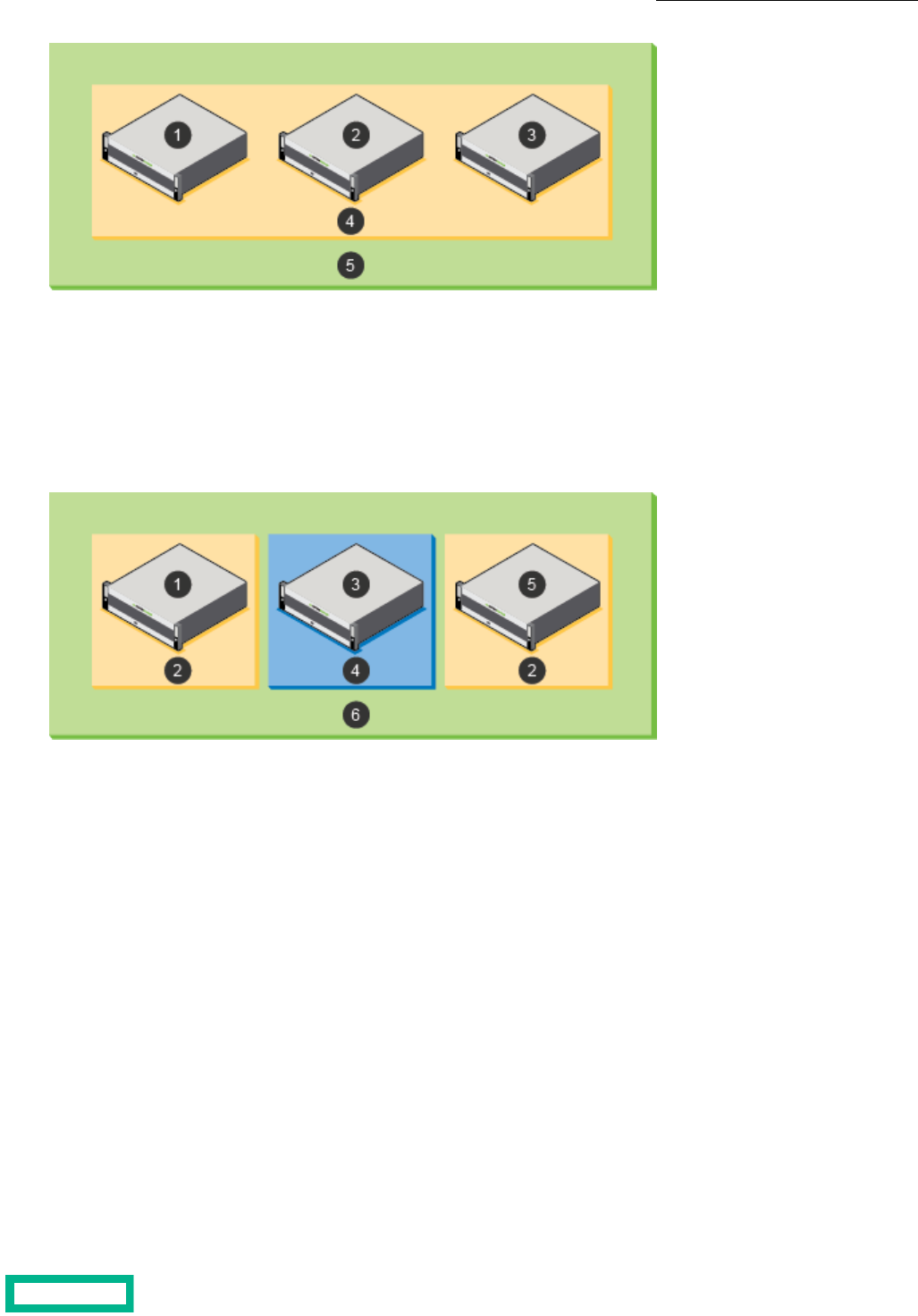
41 Default poolArray 1
2 5Array 2 Multi-array group that includes arrays 1, 2, and 3
3 Array 3
The second implementation example shows two pools that allow a specific application, such as Microsoft Exchange, to use
volumes that are spread across two of three arrays in the group, but not use the storage on a third array. In this scenario, the
storage on the array labeled 3 is in the default pool. To configure this example, remove the arrays labeled 1 and 5 from the
default pool, and then create an Exchange storage pool by adding only the arrays labeled 1 and 5 to the pool.
41 Default poolArray 1
2 5Exchange pool Array 5
63 Multi-array group that includes arrays 1, 3, and 5Array 3
The third implementation example shows adding a new array that is labeled 6 to the group that is assigned to the default
storage pool. In this scenario, you have other alternatives. One alternative is to move array 6 to the previously created Exchange
pool. Another alternative is to create a new storage pool for array 6 and leave only array 4 in the default pool.
Storage Pools 106
Documentation Feedback: [email protected]
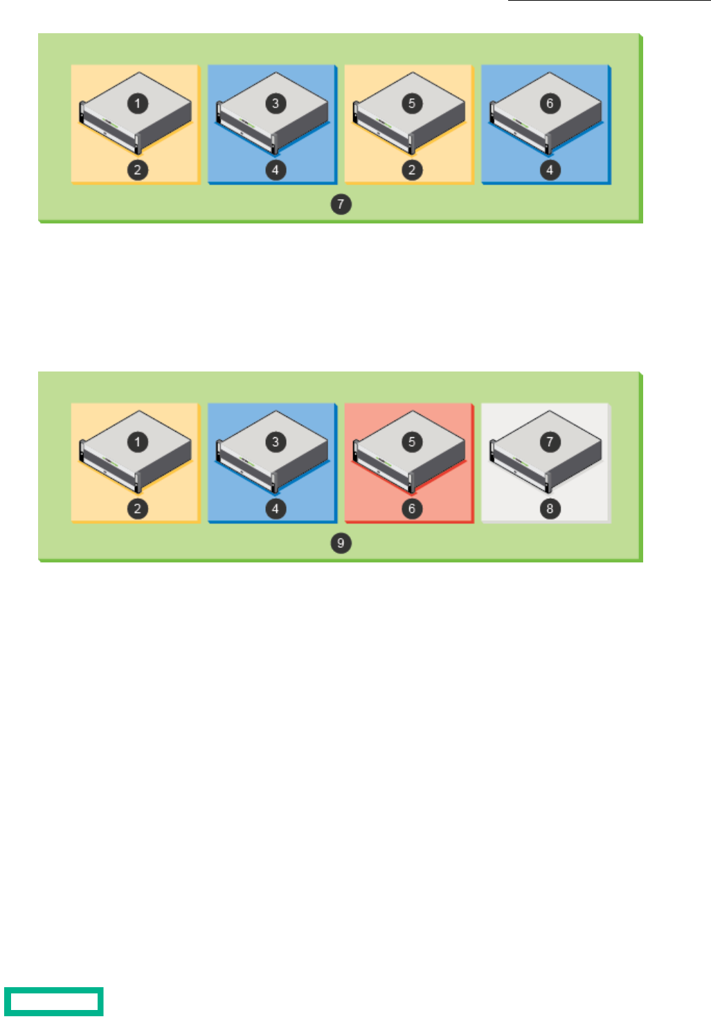
51 Array 5Array 1
2 6Exchange pool Array 6
73 Multi-array group that includes arrays 1, 3, 5,
and 6
Array 3
4 Default pool
The fourth implementation example shows having one group with four HPE arrays, where each array is in a separate storage
pool.
61 SQL Server poolArray 1
2 7Exchange pool Array 7
83 VDI poolArray 3
4 9Default pool Multi-array group that includes arrays 1, 3, 5, and
7
5 Array 5
Create a Storage Pool
By default, the arrays in a group can access each other and are grouped into a default pool. You cannot change the default
storage pool, but you can add additional storage pools and move volumes between the pools.
A pool confines data to a subset of the arrays in a group. Data of resident volumes is striped and automatically rebalanced
across all members of a group. Pools dictate physical locality and striping characteristics. Think of a pool as a logical container
that includes one or more member arrays in which volumes reside. A member array and all of its expansion shelves can only
be part of one pool.
Before you begin
You must have at least one unassigned array to put into the new storage pool.
You can also create a new storage pool when adding an array to a group.
Storage Pools 107
Documentation Feedback: [email protected]

Procedure
Create a storage pool.
pool --create pool_name --description description --array array
Example
Creating a pool with a description for the array c30-array6:
$ pool --create 1pool1 --description pool_for_admin --array c30-array6
Add or Remove Arrays from a Storage Pool
You can modify storage pools to add or remove arrays. Only one pool can be assigned to a given array. Multiple arrays can
be assigned to the same pool.
You cannot add an array to an existing pool that has synchronous replication enabled.
Note: A pool must always have one member array.
CAUTION: Exercise caution when you change a storage pool assignment because it may result in a large migration
of data.
Procedure
To add an array to a storage pool or remove an array from a storage pool, use the appropriate command:
• pool --assign pool_name [--array array] [--allow_lower_limits {yes|no]
or
• pool --unassign pool_name [--array array] [--force]
When assigning an array to a pool, set the --allow_lower_limits option to yes to allow the array to be assigned to the pool,
but reduce the limits of the array to match those of the other arrays in the pool.
When assigning an array from a pool, use the --force option to forcibly removes the array from the pool.
Merge Storage Pools
You can merge two storage pools to combine the contents of both pools. To merge multiple pools, merge two pools at a time
until the desired storage pool is created.
Note: You cannot merge pools that have synchronous replication enabled.
Important: Deduplication Domains cannot be merged, see Domains on page 92 for details.
Procedure
Merge storage pools.
pool --merge pool_name [target target]
Repeat this step for each of the pools you want to merge into the target.
Storage Pools 108
Documentation Feedback: [email protected]

Example
Merge Pool1 to Targetpool1:
Nimble OS $ pool --merge Pool1 target Targetpool1
Volume Moves
Volume move operations allow you to move volumes between folders or between pools.
Important notes about volume moves:
• Volume moves are not supported for volumes configured for synchronous replication.
• You should always use storage vMotion to move VMware virtual volumes (vVols) from the vCenter. Moving vVols using
the GUI can be a highly disruptive operation and can lead to a loss of data or VM accessibility
When you move a volume from one pool to another, parts of the volume might exist on either the pool or a folder of that pool.
When the move is complete, the data exists only on the destination pool or folder. It is not preserved on the source pool or
folder.
The two most common reasons to move data are to increase performance by moving a volume from a single-array pool to a
multi-array pool or to manually balance space usage between pools.
When you move a volume between pools, you also move all of its snapshots and clones. User access permissions and encryption
settings move with the volume.
During a move, the change from one pool to another is transparent. There is no disruption of service, and, during the move
process, any write is made to the current location of that part of the volume. A move between pools can require some time,
depending on the amount of data in the volume, the number of clones, and the pools being migrated to and from. A move to
or from a folder is almost immediate.
Important: During a move, some volume data will reside partially on both pools; consequentially, when performing
a move, you must use the HPE Storage Connection Manager on the host to facilitate the move. You should also use
Connection Manager to check hosts for old connections to targets that connect directly to data IPs.
If these connections exist, then for each target, perform one of the following tasks:
• Confirm that other connections to the corresponding group discovery IP exist.
• Establish new connections that point to the corresponding group discovery IPs before disconnecting these old connections.
In addition, make sure you perform the same checks for any defined static, favorite, or persistent targets and update any
connections as necessary.
Volumes can be moved independently or simultaneously with other volume-move operations. However, while in the process
of a move, you cannot start another move on the same volume.
Note: For Fibre Channel groups, in order to avoid losing data paths between the host and the volume being moved,
it is recommended that you check that Fibre Channel connectivity exists between the host and the arrays in an FC
group prior to initiating a volume move operation.
Move a Volume from One Storage Pool to Another
Moving a volume also moves its snapshots and clones from one storage pool to another.
Depending on the size of the volume and the amount of data, it could take some time to complete a move from one storage
pool to another. During this time, writes are allowed. Some forwarding of I/O requests from arrays in the source pool to arrays
in the destination pool can occur during the move. This can result in temporarily reduced I/O throughput.
The destination pool must have sufficient space to accommodate current use and reserve space for all volumes being moved.
Storage Pools 109
Documentation Feedback: [email protected]

At any point during a move, an administrator can stop the move. When a volume move is stopped, all data that has already
moved onto the destination pool moves back to the source pool. This may take some time, depending on the size of the pools
and how much data has been moved.
Procedure
Move a volume to a destination pool.
vol --move vollist [--dest_pool dest-pool] [--pool pool_list]
Important:
The --pool pool_list option is required if the names of one or more volumes in the volume list is not unique within
the pool.
Example
Moving a volume to a new destination pool.
$ vol --move vol22 --dest_pool poolA
Move a Volume from One Folder to Another
Moving a volume also moves its snapshots and clones from one folder to another.
Depending on the size of the volume and the amount of data, it could take some time to complete a move. During this time,
writes are allowed. Some forwarding of I/O requests from arrays in the source folder to arrays in the destination folder can
occur during the move. This can result in temporarily reduced I/O throughput.
The destination folder must have sufficient space to accommodate current use and reserve space for all volumes being moved.
At any point during a move, an administrator can stop the move. When a volume move is stopped, all data that has already
moved onto the destination folder moves back to the source folder. This may take some time, depending on the size of the
folders and how much data has been moved.
Procedure
Move a volume to a pool and assign all volumes to a folder in the destination pool.
vol --movevollist [--dest_folder folder_name] [--pool pool_list]
Important:
The --pool pool_list option is required if the names of one or more volumes in the volume list is not unique within
the pool.
See vol in the Command Reference for more information about volume moves.
Stop a Volume Move in Progress
You can stop an in-progress volume move at any point before completion. All data already moved into the destination pool
moves back to the source pool.
Stopping a volume move can take some time, depending on the size of the pools and how much data has been moved.
If you need to undo a volume move after the move is completed, you must perform a second volume move back to the original
pool.
Procedure
Stopping an in-progress volume move.
Storage Pools 110
Documentation Feedback: [email protected]

vol --abort_move vol_name [--pool pool_name]
Important:
The --pool pool_name option is required if the volume name is not unique within the group.
Example
Stop the move of vol22 from the pool Admin.
$ vol --abort_move vol22 --pool Admin
Delete a Storage Pool
You can delete a storage pool that is obsolete or no longer used after you add its member arrays to other storage pools.
Note: The default storage pool cannot be deleted.
Before you begin
• Before you delete any other storage pool on an array, move its associated volumes to another pool or remove the volumes.
• An alternative to deleting a pool is to merge it into another pool on an different array. The result is that the source pool
no longer exists and the destination pool contains any volumes that were in the source pool. There must be enough space
in the destination pool for the space occupied by the volumes and snapshots of the source pool.
Procedure
Delete a storage pool.
pool --delete pool_name [--force ]
The --force option forcibly deletes the pool even if it contains deleted volumes whose space is being reclaimed.
Example
Deleting a storage pool.
$ pool --delete MyPool
Storage Pools 111
Documentation Feedback: [email protected]

Data Protection
Ensuring that your data is protected is a critical part of managing arrays. Volumes that hold multiple components of an
application, such as databases and transaction logs, can be grouped into volume collections. A volume collection includes a
set of protection schedules that create snapshots of each associated volume at specified intervals.
The protection schedule specifies the downstream partner where the volume and snapshot data is replicated as well as
information about how often the snapshots are taken and how long the snapshots are retained.
A volume collection can have up to ten protection schedules and up to two downstream partners when you select the replication
type of Periodic Snapshot. Generally, each application uses a different volume collection.
Arrays ships with several predefined protection templates. These templates include information that is based on best practices
for commonly used applications. You can copy the predefined templates and modify the copies, or you can create new protection
templates to best match the requirements of applications used in your environment.
All volumes assigned to the volume collection use the same protection schedules, which specify downstream partners, scheduled
snapshots, replication, and retention settings. After the volume collection is created, it can be modified as needed.
If you plan to take snapshots of volumes manually, you can create a volume collection without schedules on those volumes.
This capability is available in the command-line interface (CLI).
Volume Collections
Volume collections are sets of volumes that share data protection characteristics, such as protection schedules for snapshots
and replication.
Snapshots for all volumes in a collection are captured simultaneously to ensure that the data across these volumes is mutually
consistent. All the volumes in a volume collection use that collection's protection schedules. Each schedule specifies the
downstream partner, when snapshots are taken, and the retention policies for the snapshots.
For disaster recovery, all volumes in a volume collection can simultaneously fail over to a replication partner. You can also
manually switch to a replication partner.
Volume collections can have up to two replication partners when you select the replication type Periodic Snapshot in the
protection template.. These can be two on-site, downstream replication partners or one on-site downstream replication partner
and one HPE Cloud Volume partner.
You can create a volume collection for each application. Each volume collection can contain up to ten schedules. These schedules
are additive, so when schedules overlap, snapshots and replicas are created for every schedule. You can create volume collection
schedules that are specific to some Microsoft applications or VMware virtual machines to ensure consistency.
When configuring protection schedules, be sure that you allow enough time for one schedule to complete before another
starts. For example, if Exchange protection schedule 1 has DB verification and replication enabled and runs every hour, and
Exchange protection schedule 2 has DB verification turned off and no replication and runs every five minutes, it is possible
that, without enough time between snapshots in schedule 2, schedule 1 will not be able to start.
Careful planning can enhance a backup strategy. For example, you might want to set the retention period for hourly snapshots
to a few days so you can back up quickly and precisely if necessary. Then you might want to retain daily snapshots for longer
periods, such as several weeks. You can define retention periods for snapshots. The protection schedule templates provided
by storage arrays have default values that keep volumes in the normal retention range, which is 150 snapshots or fewer,
retained either locally or on the replication partner. Although you can configure volumes with a high snapshot retention
schedule, it is not recommended. As you define protection schedules, a meter identifies when you reach the high retention
range. A mouse-over tooltip identifies the issues with defining protection schedules that exceed the normal retention range.
Note: Volumes that have a high snapshot retention schedule count in the snapshot limits for the volume, group, and
pool.
Data Protection 112
Documentation Feedback: [email protected]

Volume Collections and Multiple Replication Partners
You can specify up to two downstream replication partners for a single volume collection when you create multiple data
protection schedules and specify a replication type of Periodic Snapshot.
Each protection schedule is limited to one replication partner. You can specify one partner for a schedule and the other partner
for a different schedule.
A volume collection can have up to ten schedules. For example, a volume collection might have Partner_A and Partner_B as
replication partners. If you set up ten schedules for the volume collection, you could have schedules one through five replicate
to Partner_A and the rest replicate to Partner_B. Or you could assign Partner_B to schedules one and two and Partner_A to
the rest of the schedules. There is no required order for assigning partners to schedules.
Note: If you attempt to specify a third replication partner in the set of schedules, you will receive an error message.
The replication partners can be either two on-site downstream partners or one on-site downstream partner and one HPE
Cloud Volume partner.
Note: You cannot have two HPE Cloud Volume partners.
Create a Volume Collection
Create as many volume collections as needed.
Note: If you have created a custom agent, specify generic for --app_sync when creating a volume collection.
Procedure
1. Create a volume collection.
volcoll --create name [--prottmpl name] [--description text] [--app_sync {none | vss | vmware | generic}] [--app_server
server] [--app_id {exchange | sql2005 | sql2008 | sql2012 | exchange_dag | sql2014 | sql2016 | sql2017 | hyperv}]
[--app_cluster_name cluster name] [--app_service_name service name] [--vcenter_hostname server] [--vcenter_username
username] [--vcenter_password password] [--replication_type periodic_snapshot | synchronous] [--agent_hostname
server] [--agent_username user_name] [--agent_password password
You can also create a volume collection from a protection template:
volcoll--create name --prottmpl name
2. (Optional) Create a replication schedule for the volume collection.
volcoll --addsched name --schedule name
3. (Optional) Create a snapshot for the volume collection.
volcoll --snap name --snapcoll_name name
Example
Creating a volume collection:
$ volcoll --create VolColA
Creating a volume collection, giving it a description, and assigning a protection template:
$ volcoll --create VolColA --description CollectionA --prottmpl ProtectA
Creating a volume collection, specifying the application-specific synchronization required, naming the host server, and identifying
the application running on the server:
$ volcoll --create VolColA --description CollectionA --app_server Host1 --
app_sync vss --app_id exchange
Data Protection 113
Documentation Feedback: [email protected]

Creating a volume collection, and specifying a Windows application cluster and service name:
$ volcoll --create VolColA --description CollectionA --app_server Host1 --app_id
exchange app_cluster Cluster1
--app_service_name Mail
Creating a volume collection, and setting a VMware vCenter host name, user name, and password:
$ volcoll --create VolColA --description CollectionA --vcenter_hostname Host2
--vcenter_username James
--vcenter_password Password
Creating a volume collection replication schedule:
$ volcoll --addsched Replication1 --schedule Schedule1
Creating a volume collection snapshot:
$ volcoll --snap Snapshot1 --snapcoll_name Snapcoll1
Creating a volume collection with --app_sync type generic:
$ volcoll --create gen-sync-test-vc1 --app_sync generic --agent_hostname
10.xx.xxx.xxx --agent_username
Administrator --agent_password Nim123#
Creating a volume collection with --app_id hyperv:
$ volcoll --create MyVolColl --app_sync vss --app_server 10.xx.xx.xxx --app_id
hyperv
Protect a Standalone Volume
Some volumes may not need to be part of a volume collection. You can associate standalone volumes with volume collections
to define their snapshot and replication schedules. The volume collection associated with a standalone volume cannot contain
any other volumes.
There is no difference between a volume collection of a standalone volume and any other volume collection from the standpoint
of the CLI.
Note: You can remove a stand-alone volume collection or remove protection from a volume in a stand-alone volume
collection by editing the volume and marking it as “Unprotected.” Then the volume can be added to a volume collection
that contains volumes that are not stand-alone.
Procedure
1. Create a volume collection.
volcoll --create name
2. Associate the standalone volume with the volume collection.
vol --assoc name [--volcoll name]
Example
Creating a volume collection:
$ volcoll --create Collection1
Data Protection 114
Documentation Feedback: [email protected]

Associating a standalone volume with the volume collection:
$ vol --assoc VolumeA --volcoll Collection1
Modify a Volume Collection
You can modify a volume collection to make it more effective in a changing environment.
Note: If you have created a custom agent, specify the generic app type when modifying a volume collection.
Procedure
1. Modify the volume collection.
volcoll --edit name [--newname name ] [--description text ] [--app_sync {none | vss |vmware | generic}] [--app_server
server] [--app_id {exchange | sql2005 | sql2008 | sql2012 | exchange_dag | sql2014 | sql2016 | sql2017 | hyperv}]
2. (Optional) Modify the replication schedule for the volume collection.
volcoll --editsched name --schedule name [--newname name ] [--repeat period] [--repeat_unit
{minutes|hours|days|weeks}] [--at time] [--until time] [--days days] [--retain number]
Example
Modifying the name and description of a volume collection, and the name of the replication schedule.
$ volcoll --edit Collection1 --newname Exchange1 --description ExhangeCollection1
Modifying a replication schedule and changing its name.
$ volcoll --editsched Protection1 --schedule Exchange1 --newname ExchangePro►
tection
Editing volume collection while providing app sync type generic and its arguments:
$ volcoll --edit gen-sync-test-vc1 --agent_hostname 10.xx.xxx.xxx --
agent_username admin
--agent_password Nim123
Delete a Volume Collection
You can delete any volume collection that has no volumes associated with it.
Procedure
1. Remove all volumes from the volume collection.
vol --dissoc name
Repeat this step until all volumes associated with the volume collection have been removed.
2. Delete the volume collection.
volcoll --delete name
Example
Removing a volume from a volume collection, then deleting the volume collection.
$ vol --dissoc Volume1
$ volcoll --delete Exchange1
Data Protection 115
Documentation Feedback: [email protected]

Protection Templates
Protection templates are sets of defined schedules and retention limits that you use to pre-fill the protection information when
creating volume collections and standalone volumes. As a result, protection templates not only minimize repetitive entry of
schedules, they also minimize errors and inconsistent setups by allowing the creation and management of a finite set of
protection templates to meet all business needs.
Note: You cannot define protection templates with synchronous replication settings.
After you create a volume collection, schedules and synchronization settings can be changed on the collection. This makes
using the protection templates an easy, fast way to create multiple volume collections that share similar schedules: Use the
same protection template to create as many volume collections as you want, then modify the volume collections with the
changes specific to the needs of each collection. This means that you can create volume collections that are grouped as logical
restoration groups.
You can create as many volume collections from the same protection template as desired. Later changes to the volume
collection will not affect the template. Likewise, changes to the protection template do not affect previously created volume
collections.
Note: You cannot edit or delete the predefined protection templates provided with the array; however, you can create
new protection templates as needed.
Important: When setting up protection schedule for a protection template, be sure that you allow sufficient time for
one schedule to complete before another one starts. For example, if Exchange protection schedule 1 has DB verification
and replication enabled and runs every hour, and Exchange protection schedule 2 has DB verification turned off and
no replication and runs every five minutes, there might not be enough time between schedule 2 snapshots for schedule
1 to start.
Create a Protection Template
Create as many protection templates as needed. You can use the ones provided by HPE, or customize your own.
Note: If you create protection templates that use replication, configure both arrays as replication partners before
creating the protection template.
Note: If you have created a custom agent, specify the generic app type when creating a protection template.
Procedure
1. Create a protection template, including a protection schedule.
prottmpl --create template_name [--description text] [--app_sync {none | vss | vmware | generic}] [--app_server server]
[--app_id {exchange | sql2005 | sql2008 | sql2012 | exchange_dag | sql2014 | sql2016 | sql2017 | hyperv}]
[--app_cluster_name cluster_name] [--app_service_name service_name] [--vcenter_hostname server] [--vcenter_username
server] [--vcenter_password server] [--schedule name] [--repeat period] [--repeat_unit {minutes | hours | days | weeks}]
[--at time] [--until time] [--days days] [--retain number] [--replicate_to partner] [--replicate_every number]
[--num_retain_replica number] [--alert_threshold hh:mm] [--snap_verify {yes | no}] [--skip_db_consistency_check
{yes | no}] [--disable_appsync {yes | no}] [--external_trigger {yes | no}]
2. (Optional) Add another protection schedule to the specified protection template.
prottmpl --addsched template_name --schedule name] [--repeat period] [--repeat_unit {minutes | hours | days | weeks}]
[--at time] [--until time] [--days days] [--retain number] [--replicate_to partner] [--replicate_every number]
[--num_retain_replica number] [--alert_threshold hh:mm] [--snap_verify {yes | no}] [--skip_db_consistency_check
{yes | no}] [--disable_appsync {yes | no}] [--external_trigger {yes | no}]
Data Protection 116
Documentation Feedback: [email protected]

Note: You can create up to ten protection schedules for the specified protection template. For example, you can
create one schedule for working hours, one for peak hours, and one for weekends. Schedules can overlap, but they
cannot span midnight.
Example
Creating a new protection template named highrepl.
prottmpl --create highrepl --description "use when high replication is needed"
--app_sync none --schedule replicated --repeat 1 --repeat_unit day
--days Monday,Tuesday,Thursday --retain 8 --replicate_to greyhound
--replicate_every 1 --num_retain_replica 40 --snap_verify no
Adding an hourly schedule to the highrepl protection template.
$ prottmpl --addsched highrepl --schedule hourly --repeat 1 --repeat_unit hours
--retain 25 --snap_verify no
Creating a protection template with app sync type generic.
$ prottmpl --create gen-sync-test-prottmpl --app_sync generic --agent_hostname
10.18.237.121 --agent_username Administrator --agent_password Nim123# --
schedule sched1 --retain 30
Edit a Protection Template
You can edit protection templates, but the changes will apply only to volume collections based on the template after it has
been changed. Existing volume collections are not affected.
Note: If you have created a custom agent, specify the generic app type when editing a protection template.
Procedure
1. Edit a protection template and at least one parameter to be changed.
prottmpl --edit template_name [--name new_name] [--description text] [--app_sync {none | vss | vmware | generic}]
[--app_server server] [--app_id {exchange | sql2005 | sql2008 | sql2012 | exchange_dag | sql2014 | sql2016 | sql2017
| hyperv}] [--app_cluster_name cluster_name] [--app_service_name service_name] [--vcenter_hostname server]
[--vcenter_username server] [--vcenter_password server]
2. (Optional) Edit an existing schedule assigned to the protection template.
prottmpl --editsched template_name --schedule schedule_name [--repeat period] [--repeat_unit {minutes | hours |
days | weeks}] [--at time] [--until time] [--days days] [--retain number] [--replicate_to partner] [--replicate_every
number] [--num_retain_replica number] [--alert_threshold hh:mm] [--snap_verify {yes | no}]
[--skip_db_consistency_check {yes | no}] [--disable_appsync {yes | no}] [--external_trigger {yes | no}]
Example
Editing the protection template named highrepl to replicate once a week, and to retain 31 snapshots and 52 replicas.
$ prottmpl --edit highrepl --schedule replicated
--repeat 1 --repeat_unit weeks --retain 31 --replicate_to array7
--replicate_every 1 --num_retain_replica 52 --snap_verify no
Editing a protection template with app sync type generic.
prottmpl --edit gen-sync-test-prottmpl --agent_hostname 10.xx.xx.xxx
Data Protection 117
Documentation Feedback: [email protected]

Delete a Protection Template
Over time, you may find that a template is no longer needed.You can delete any user-defined protection template without
affecting existing volume collections.
Procedure
Delete a specified protection template.
prottmpl --delete template_name
Example
Deleting the protection templae named highrepl.
$ prottmpl --delete highrepl
Data Protection 118
Documentation Feedback: [email protected]

Replication
You can use volume replication to copy critical data to arrays at different locations as part of your disaster recovery strategy.
Replication does not take the place of snapshot backups, but it enhances the overall data recovery plan.
For data recovery tasks like recovering an accidentally deleted or corrupted file, you can take snapshots that serve as a backup.
Snapshots have little performance impact, can be performed quickly, and are space efficient.
For more widespread issues like a power failure or a site disaster, replication technology can be a quick and effective way to
recover data at an offsite location. In these scenarios, data can be served from the replica while the initial array is being restored.
Storage arrays use an advanced file system that provides in-line compression for data writes. Data is stored in variable-length
blocks that match the logical write methodology of an application. These features minimize the amount of replication traffic
to a compressed version of the logical application write and reduce bandwidth requirements.
Snapshot replication tasks are scheduled automatically through protection templates. You can implement any number of
replication strategies to meet your requirements for disaster recovery. For more information on protection templates, see the
chapter on Data Protection.
What is Replication?
Replication maintains a copy or replica of a volume or set of volumes and their snapshots on another array that is configured
as one of a pair of replication partners. The replica contains the contents of a volume at the time the replica was created or
last updated, as well as a configured number of prior states (snapshots). Replicas are stored at a remote array, called a
replication partner, connected by a network or Internet link. A volume is always located on a different array than its replica.
It is possible to retain more or fewer snapshots on the replica than on the source volume, thus providing greater flexibility in
designing a recovery plan.
The HPE Peer Persistence feature is designed for applications that require zero to near zero RPO and RTO storage. The
feature enables multi-site synchronous replication with automatic switchover (ASO), which allows your arrays to recover
automatically and non-disruptively from a storage based failure. For the purposes of this documentation, the two components
of HPE Peer Persistence are referred to by their functional descriptions, synchronous replication and ASO, rather than the
feature name.
Note: The HPE Peer Persistence feature is designed to enable applications to achieve a near zero RPO only in the
event of storage failures. The feature will not prevent site-to-site failures that result from host level failures.
A replica is a copy of a volume from another group (in the case of snapshot replication) or pool (in the case of synchronous
replication) whose state is managed by the other group or pool. For example, all write operations to a replica originate from
another group. The array that hosts the original volume and manages the state of a replica is called the upstream partner,
because the data flows from it. The array where the replica resides is called the downstream partner, because the data flows
to it.
The replicated volumes can be restored as complete copies of the volumes, with all schedules and administrative settings
replicated, as well as the actual data. Like snapshots, replicas are created and stored based on volume collection schedules.
Multiple volumes can share a volume collection schedule.
For snapshot replication only: When you promote a replica, the number of snapshots to retain is adjusted to be the maximum
number of snapshots to retain on the local array, plus the number of snapshots to retain on the replica. The volume is offline
until a replica is promoted. The volume and settings are visible on the replica, but they are not editable until a volume collection
handover is performed.
Note: For synchronous replication, the snapshot retention limits remain with each pool after a handover.
Replication 119

Snapshot Replication and Synchronous Replication
There are two types of replication: snapshot replication and synchronous replication. Snapshot replication creates a backup
version of your volumes so that you have a point-in-time copy to refer back to if a prior version of the data is needed.
Synchronous replication provides a replica of the volumes that is created synchronously with no delay in the recovery point.
It is intended for immediate recovery due to a site failure.
To assist in understanding the differences between snapshot replication and synchronous replication, the following table
presents a comparison of the two.
NotesSynchronous ReplicationSnapshot ReplicationBehavior
Failures caused by incorrect
writes are not covered by
synchronous replication. They
can be recovered from snap-
shots.
0 RPO
Note: RTO can be <
1 minute when in a
single site or when
metro stretch cluster-
ing is not being used.
Depending on the replication
snapshot schedule. If the
schedule is 15 minutes, then
the RPO is 15 minutes
Recovery Point Objective
(RPO)
Only available with syn-
chronous replication when ac-
companied by the Automatic
Switchover (ASO) on page 129
feature.
Yes, if Automatic Switchover
is configured
NoAutomatic recovery
YesYesManual recovery
Pool partners are auto-gener-
ated and deleted when the
pool is deleted or merged
Pool partnersGroup partnersReplication Partners
12Maximum number of partners
512 volumes upstream and
512 volumes downstream
1024 volumesNumber of protected volumes
Synchronous replication is not
allowed on multi-pool volume
collections
Volume collectionVolume collectionReplication configuration level
1010Maximum number of protec-
tion schedules per volume
collection
Two arrays, two single-array
pools
The maximum supported
number of groups is four
Extent of replication
Within groupBetween groupsReplication type
YesYesReplicate sub-set of Snap-
shots
For synchronous replication,
the upstream array must be
the same model as the down-
stream array
AFxx, HFxx, AFxxxx, CSxxxx,
and HPE Alletra 6000 arrays
only
All modelsHardware array models sup-
ported
Replication 120
Documentation Feedback: [email protected]

NotesSynchronous ReplicationSnapshot ReplicationBehavior
Soft synchronous mode where
when a volume goes out-of-
sync, it continues to accept
writes
N/ASynchronous mode
Yes, through an automatic
resynchronization
YesResume automatically
YesYesSite fault tolerance
Switchover can be completed
in under one minute
User initiated handover can
be completed in under one
minute
Recovery time objective (RTO)
IPIPNetwork connectivity for
replication traffic between
partners
NoYesSupport for multiprotocol ar-
rays (Fibre Channel and iSCSI)
10 GpbsN/ALink bandwidth
At least two links are recom-
mended for redundancy and
performance
At least one. Additional links
can be added for redundancy,
however traffic occurs over a
single IP and port.
Number of links
YesYesAdd support non-disruptively
YesYesRemove support non-disrup-
tively
Note: To replace an
array, un-configure
synchronous replica-
tion, move data to a
new array, then re-
configure syn-
chronous replication.
Yes, see noteYesArray replacement allowed
NoNoChanging replication type al-
lowed
Note: To resize a
volume with syn-
chronous replication,
unconfigure syn-
chronous replication,
resize the volume,
then reconfigure
synchronous replica-
tion.
Yes, see noteYesVolume resize support
Replication 121
Documentation Feedback: [email protected]

NotesSynchronous ReplicationSnapshot ReplicationBehavior
All arrays must be in the same
subnet
Arrays do not need to be in
the same subnet
Subnets
None providedYesProtection templates
All in one volume collectionIn separate groups, so in sepa-
rate volume collections.
Location of upstream and
downstream replicated vol-
umes
Two separate snapshot collec-
tions, one for upstream and
one for downstream
In separate groups, so in sepa-
rate snapshot collections.
Location of snapshots
NoYesHost reconfiguration required
after handover
Link Management and Resynchronization with Synchronous Replication
Resynchronization is a process where data is sent from the upstream pool partner to the downstream pool partner to ensure
that the data at both partners is in-sync, or the same. If the two sites become out-of-sync, for example, through a pause in
system connectivity, a resynchronization is performed to bring the two sites back in-sync.
Upon creation, the entire data set from the upstream volume collection is sent to the downstream volume collection. This is
the initial synchronization, also known as seeding.
When a link breaks, such as a TCP link or a TCP connection and cannot be reestablished for 30 seconds, the volume transitions
to an out-of-sync state.
When the volume collection is out-of-sync, new writes are not replicated to the downstream partner.
After the TCP link is restored, a resynchronization is needed to bring the arrays back into an in-sync state. The replicated
volumes are scanned, and blocks that have been written since the link broke are sent to the downstream array. Volumes
continue to accept I/O during the resynchronization process, and when the resynchronization is complete, the volume collection
returns to an in-sync state.
In some cases a resynchronization sends more than just the missing data. For example, when you restore a volume to a snapshot
or a new volume is created by cloning, the resynchronization process sends all data that has changed since the last snapshot
that is common between the upstream and the downstream volume.
This type of resynchronization also happens if you remove (unconfigure) synchronous replication from a volume, and later
reconfigure it, for example, by removing and later re-adding the volume to its volume collection, or by removing and recreating
the synchronous replication schedule.
Replication Partners and How Replication Works
Note:
Replication partners can be referred to differently depending on which type of replication is being used. The following
describes the different types of replication partners:
• For snapshot replication: Group partners
• For synchronous replication: Pool partners
• For HPE Cloud Volumes (CV) replication: Replication store on the HPE CV portal
Note:
Replicating encrypted volumes to HPE CV requires release 5.0.6.x or later.
Replication 122
Documentation Feedback: [email protected]

You can configure arrays to have up to fifty snapshot replication partners. Synchronous replication allows only one pool
partner. Snapshot and synchronous replication are both automatic, based on the protection schedules assigned to the volume
or volume collection.
Replication partners can be reciprocal, upstream (the source of replicas), or downstream (the receiver of replicas) partners.
You can have several upstream arrays that replicate to one downstream partner. For synchronous replication, pool partners
are created automatically after replication is configured.
When you enable replication of a volume for the first time, the entire data set on the volume at the time of the snapshot is
replicated from the original array group (upstream) to the destination replication partner (the downstream array group).
Subsequent updates replicate the differences between the last replicated snapshot on the upstream partner to the downstream
partner.
It is recommended that you configure the snapshot retention count on the replica (downstream) array group to at least the
number of snapshots on the upstream array group, matching the frequency of snapshots.
Note: In the majority of array operating system releases, by default, the replication partner retains only two snapshots
for each replica volume in the volume collection if configuration is not adjusted.
Replication partners can use different access protocols. One of the partners can be an iSCSI array and its replication partner
can be a Fibre Channel array.
Snapshot collections are replicated in the order that the collections were taken. Once replication is caught up, the upstream
and downstream replication partners only retain as many snapshots as set in the retention criteria. The system deletes pending
snapshot collections that exceed the retention criteria.
Add Replication to a Volume Collection
Before you can set up replication, you need to configure replication partners, also known as group partners for snapshot
replication, pool partners for synchronous replication, and replication stores on HPE Cloud Volumes (HPE CV). Creating
replication partners automatically enables two arrays or an array and HPE CV to replicate volume collections.
If you want to specify synchronous replication as the replication type on a volume collection, you must do that when the
volume collection is created. After you designate it as a synchronously-replicated volume collection, the replication type cannot
be changed.
When using snapshot replication, volume collections support up to two replication partners. You specify the replication partners
when you create protection schedules for a volume collection. A volume collection can have up to ten schedules. You can set
up the schedules so that certain ones use one of the replication partners and others use the other replication partner.
Note: You will receive an error message if you attempt to add a third replication partner to the schedule set for a
volume collection.
Before you begin
You must have a volume collection to create replicas. You cannot create replicas on demand.
Procedure
1. If the volume collection does not include a replication partner in the schedule, edit the volume collection to add a replication
partner.
volcoll --editsched name --schedule name --replicate_to name--retain number --num_retain_replica number --repeat
period --repeat_unit minutes | hours | days | weeks
2. Modify each volume to assign the volume to a volume collection.
vol --assoc name --volcoll name
Replication 123
Documentation Feedback: [email protected]

Results
The volumes of this volume collection are now replicated to the designated replication partners according to the assigned
volume collections schedule.
Create a Replication Partner
Note: This procedure does not apply to synchronous replication. The replication partners for synchronous replication
are pool partners and are created automatically.
Use the management subnet for replication when any of the following conditions apply:
• Your data IPs are not routable across the network
• You want to separate replication traffic from iSCSI traffic
• Your replication arrays are running array OS 1.4 or array OS 2.0 and above
Note:
For array OS 2.x and later, replication over a data subnet is available; however, it requires the replication control traffic
to be transferred over a management subnet. If you choose to replicate over a data subnet, you must be able to do
the following:
• Route the management subnet between replication partners by the default gateway for replication control traffic
• Route the data subnet between replication partners by a static route for replication data transfer traffic
Replication partners can run different data access protocols. For example, a Fibre Channel (FC) replication partner can be
created for an iSCSI array, and an iSCSI replication partner can be created for a Fibre Channel array. For replication to function
on an FC array, you must also configure an Ethernet link or IP subnet.
For Fibre Channel arrays, you do not need to separate the replication traffic; replication traffic never runs over Fibre Channel.
Procedure
1. Determine the IP address or hostname of the array to be used as a replication partner.
2. Add a replication partner.
partner --create partner_name --hostname [ipaddr|hostname]--description text --secret shared_secret
A description is optional. The shared secret must be eight or more printable alphanumeric characters with no spaces or
special characters. Special characters include: ' " ` ~ ! @ # $ ^ & ( )+ [ ] {} * ; : ' " . , | < > ? / \ = % .
3. (Optional) Select the replication network.
partner --edit partner_name--subnet local_subnet_label
Use the --subnet option only when there are multiple data subnets. When you use the local_subnet_label variable, include
the full subnet address and mask, separated by a slash. For example, 172.18.120.0/255.255.255.0
4. (Optional) Create a QoS (replication traffic bandwidth limit) policy.
A Quality of Service (QoS) policy defines how the network resources are allocated for the replication partner.
Note: Without a QoS policy, the replication partner can use unlimited network bandwidth.
partner --create_throttlepartner_name --description text --days days --at start_time --until end_time --bandwidth
limit
What to do next
Log in to the replication partner and perform the same configuration steps on the downstream array and group.
Replication 124
Documentation Feedback: [email protected]

Modify a Replication Partner
You can modify the IP address or bandwidth requirements for a replication partner without having to recreate the replication
partner.
You cannot change the name of a replication partner. In this case, create a new replication partner with the required name,
assign the volume collection to the new replication partner, and delete the original replication partner.
This procedure does not apply to synchronous replication. You can only change the description and the secret on the pool
partner.
For synchronous replication, you cannot rename a pool partner. If a pool is renamed, the pool partner will be renamed
automatically.
Procedure
Modify the replication partner.
partner--edit
partner--edit_throttle
Delete a Replication Partner
Note: When you delete a replication partner relationship, only the replication partner relationship is deleted, not the
array.
This procedure does not apply to synchronous replication. For synchronous replication, you cannot delete pool partners. Pool
partners are deleted based on the number of pools in the group.
Before you begin
• Change all volume collections so that replication is not scheduled with a partner.
• Ensure that there are no volume collections that have the replication partner selected.
• Be sure to remove both the upstream and downstream replication partners.
Procedure
Delete a replication partner.
partner --delete partner_name
If you removed all volume collection schedules from the source group, you can view the confirmation that the replication
partner was deleted. If there are still active schedules associated with the partner, delete those and repeat the process.
You may want to promote the volume collection on the downstream partner before you delete it.
Test the Connection between Replication Partners
You can test the connection between configured replication partners at any time.
Procedure
Test the connection between replication partners.
partner --test partner_name
Replication 125
Documentation Feedback: [email protected]

Synchronous Replication
Synchronous replication provides protection from array or site failures with no data loss. It provides a zero recovery point
objective, meaning that there is no data loss in the event of an array or site failure. This is not available with snapshot replication.
Synchronous replication ensures that host reconfiguration is not required.
Synchronous replication allows you to protect the entire array and enable or disable protection simply by adding or removing
it in the protection schedule.
You can also use the Peer Persistence feature, which combines synchronous replication with automatic switchover (ASO).
Peer Persistence allows your arrays to recover automatically and non-disruptively from a storage based failure. For the purpose
of this documentation, the two components of Peer Persistence are referred to by their functional descriptions, synchronous
replication and ASO, rather than the feature name.
For more information on ASO, see Automatic Switchover (ASO) on page 129.
Synchronous Replication Prerequisites and Limitations
The following list includes requirements and limitations for the use of synchronous replication.
General Limitations
• Array group can consist of only two single array pools
• Multi-array pools are not supported
• Synchronous replication of multiple pool volume collections is not supported
• Moving synchronously replicated volumes between pools is not supported
• The maximum number of replication volumes is 512 upstream and 512 downstream volumes
• Synchronous Replication is not supported on the HF20H, CS1000H, or SFAxxx arrays.
• The hardware models must be the same for all arrays in the synchronous replication relationship
• A 10G link between the sites (Ethernet, not FC) is required
• Round trip latency between the sites should be less than or equal to five msec.
• You must install the latest host and client components
• Synchronous Replication only works through storage failover and does not support host level failover.
Operations and Features not Supported with Synchronous Replication
• Volume encryption
• Volume pinning
• Volume striping
• Volume resizing
You must unconfigure synchronous replication to resize a volume.
• Volume move
• Folder space limits enforcement
• Snapshot replication
A volume collection cannot be configured for both snapshot replication and synchronous replication.
• HPE Cloud Volume (CV) replication
• Virtual arrays
• Virtual volumes (vVols)
• SMI-S volumes
• Changing replication type
• Array replacement
You must unconfigure synchronous replication to replace an array.
Replication 126
Documentation Feedback: [email protected]

• Multiprotocol arrays (FC and iSCSI)
• Volume restore
You must unconfigure synchronous replication to restore a volume.
Out-of-Sync Volumes
A volume collection is in-sync only if all upstream volumes in the volume collection are in-sync.
If the replication link breaks, after about 30 seconds, the volume collections transition to an out-of-sync state, and writes are
accepted without being replicated. When the link is restored, the system performs a resynchronization and the volume
collections transition to an in-sync state with all incoming writes written to both arrays before acknowledging the hosts.
Note: If you add a volume to a synchronously-replicated volume collection, all the volumes that are configured for
synchronous replication will go out-of-sync until the newly added volume is in-sync.
Snapshots taken while the volume collection is out-of-sync are not replicated and the snapshots will only be created on the
upstream volumes.
It is not possible to catch-up or replicate any snapshots that were missed while the volume was out-of-sync.
When the volume is out-of-sync, the Recovery Point Objective (RPO) is not zero. The volume might be out-of-sync due to a
variety of reasons such as a resynchronization that is in progress, I/O might have been paused, the user editing the volume
collection, or some other reason.
To check the state of the volume, you can run the volcoll --info [volume_name] command.
Volume Names and Replication
You can have multiple volumes with the same name. The following list states conditions to consider if you have more than
one volume with the same name.
• A volume replicated within a group will have two separate instances with the same name but they must be in different
pools.
Both volumes will show up in the list of volumes with an indication of which pool the volume resides in.
• Operations that would put two volumes with the same name within the same pool, for example volume move or pool merge,
will fail.
Configuring Synchronous Replication on a Volume Collection
You can configure synchronous replication for the volume collection. A volume collection includes a set of protection schedules
for creating snapshots of each associated volume at set intervals. The protection schedule specifies the downstream partner
where the volume and snapshot data is replicated.
• All upstream volumes in a synchronously replicated volume collection must belong to the same pool.
• Two different volumes with the same name in the downstream pool are not supported.
• All synchronous replication schedules must use the same downstream pool partner.
Important: If you add a volume to a synchronously replicated volume collection, all the volumes that are configured
for synchronous replication will go out-of-sync until the newly added volume is in-sync.
You must create a snapshot schedule and configure the schedule with a replication partner. Creating a snapshot schedule and
a replication partner allows you to perform a roll back operation, if necessary, or create clones from the snapshots.
Important: You must set up the schedule so that at least one replicated snapshot is taken every four hours. If you
specify a longer time interval, you will get an alert notifying you that the schedule does not meet time recommendations
for snapshots.
Replication 127
Documentation Feedback: [email protected]

For a new synchronous replication configuration, downstream volumes are automatically created. If any downstream volumes
exist from previous synchronous replication, they are re-used. The downstream volume inherits the state of the existing
upstream volume (either online or offline).
After you configure synchronous replication for a volume collection, the following actions take place:
• A downstream volume is created in the pool partner that has the same name and is automatically added to the volume
collection.
• The volumes in the downstream volume collection inherit the serial number and the existing ACLs from the upstream
volumes.
• The volumes in the downstream volume collection are brought online to export the iSCSI standby paths.
For detailed instructions for creating a volume collection and configuring synchronous replication on a volume collection, see
Create a Volume Collection.
Configuring Synchronous Replication: Serial Numbers and ACLs
Serial Numbers
When synchronous replication is configured, the upstream and downstream volumes share the same serial number. On the
host, there are multiple paths to a single iSCSI device with a single serial number: active paths are mapped to the upstream
volume, the standby paths are mapped to the downstream volume.
From the Array System Management view, the upstream and downstream volumes are different management objects. The
upstream volume has the serial number that was exported through the data path. The downstream volume has a different
serial number (a secondary serial number). When synchronous replication is unconfigured, the downstream volume can be
exported on the data path as an independent volume with this secondary serial number.
A handover operation switches the serial number between the upstream and the downstream volume.
ACLs
After synchronous replication has been configured, the downstream volume inherits the existing ACLs (and respective LUNs)
from the upstream volume. While configured for synchronous replication, all access control changes affect both volumes. You
can add or remove ACLs from either the upstream or downstream volume.
When you want to re-use an existing volume as a downstream volume for synchronous replication, you must manually move
all existing ACLs to the new downstream volume.
When synchronous replication is unconfigured, the upstream volume retains all ACLs (and respective LUNs) to maintain the
data service. All ACLs are removed from the downstream volume.
Unconfigure Synchronous Replication
There are several ways to unconfigure synchronous replication.
• Disassociate all volumes from the synchronous replication volume collections.
• Delete the last synchronous replication schedule with a pool partner.
• Remove a pool partner from the last synchronous replication schedule.
When synchronous replication is unconfigured, the downstream volume is brought offline and standby SCSI paths are removed.
Reconfigure Synchronous Replication
There are several advantages to reconfiguring synchronous replication:
• Reconfiguring a volume that had been synchronously replicated previously does not require a full reseed of the data.
• You can identify a prior downstream volume in a pool partner with the same name.
• The process automatically triggers a resynchronization from a snapshot which brings the upstream and downstream sites
into sync.
Replication 128
Documentation Feedback: [email protected]

Before you begin
• The downstream volume must be offline.
• The downstream volume must share a common snapshot with the upstream volume.
• The downstream volume must not have any existing ACLs.
Procedure
1. Configure synchronous replication.
See Create a Volume Collection on page 113 .
2. Unconfigure synchronous replication.
See Unconfigure Synchronous Replication on page 128.
3. Reconfigure synchronous replication.
Automatic Switchover (ASO)
Important: Check the latest release notes before you attempt to use the Peer Persistence feature.
Automatic Switchover (ASO) is an optional, but highly recommended, feature that can be used with synchronous replication
to enable automatic failure recovery. When ASO is used in conjunction with synchronous replication, the feature is known as
HPE Peer Persistence.
The HPE Peer Persistence feature enables synchronous replication with ASO, which allows your arrays to recover automatically
and non-disruptively from storage based failures.
Note: The HPE Peer Persistence feature is designed to enable automatic recovery failure in the event of storage
failures. The feature will not prevent site-to-site failures that result from host level failures.
ASO currently works on array groups that consist of two arrays. When ASO is enabled and a switchover occurs, the partner
that serves I/O for a volume collection is switched, which non-disruptively reverses the direction of the synchronous replication.
ASO facilitates automatic failure recovery through the use of a Witness daemon that can be run on an independent host (or
in a separate VM) that can communicate with the group leader and the backup group leader.
Note: The Witness does not need to be on the same subnet as the array group, but its IP address must be routable
from the array group’s management network. The Witness can be installed in a different data center or even in a cloud
environment as long as the round-trip time (RTT) between the Witness and the two arrays is 250 milliseconds or less.
Multiple methods exist to deploy the Peer Persistence Witness. If the Witness is installed in a different data center or
cloud environment and HPE Storage Support is needed to resolve an issue with the Witness, consider that if HPE
Storage Support cannot access the data center, cloud environment, or infrastructure, troubleshooting may be limited.
When the Witness detects that an array is unavailable, the ASO process performs a handover of affected synchronous replication
volume collections and seamlessly maintains the availability of group services and of synchronously replicated volumes.
To enable ASO, you must perform one of the following procedures:
• Install and configure the Witness software on a CentOS V7.9.x. client.
• Run the Witness in a separate VMware based Virtual Machine.
After the Witness is configured, you can then use the array OS GUI or CLI to set up the Witness and enable Automatic Switchover
between the arrays in the group.
Note: The ASO check box is selected by default; however, ASO is not actually enabled unless the Witness is configured.
For example, you might go to Administration > Availability in the array OS GUI and see that Enable is checked for
Automatic Switchover, but the fields for the Witness are blank. In this case, ASO is not enabled. You must both configure
the Witness and check the Enable box for ASO to be configured.
Replication 129
Documentation Feedback: [email protected]

Tip: You can use the following group command to enable or disable ASO from the CLI.
group --edit --auto_switchover_enabled {yes|no}
For information about enabling, deploying, and testing the HPE Peer Persistence feature, including possible ASO failure
scenarios, refer to HPE Peer Persistence Deployment Considerations in the HPE InfoSight documentation portal.
Install and Configure the Witness on a Linux server
Note: Installing the Witness on a Linux server is just one option for enabling ASO. If you prefer not to maintain a
separate Linux Server, you can elect to run the Witness in a virtual machine. The Witness must be on the same
management subnet as the arrays.
To install an configure the Witness on a Linux server, complete the the following steps:
Before you begin
Download the Witness software from InfoSight.
Procedure
1. Install the Witness software on a CentOS V7.7.x server.
yum -y install /root/<nimble-witness-software>.rpm
A service called nimble-witnessd.service is created.
2. Enable the Witness process to automatically start when the system boots.
systemctl enable nimble-witnessd.service
3. Start the Witness process.
systemctl start nimble-witnessd.service
4. Display the status of the Witness process.
systemctl status nimble-witnessd.service
A a message appears stating that the Witness is enabled. The port number that the process is running on is also displayed,
which you may need to configure your firewall.
5. Create a user and password for the Witness.
useradd <witness_user_name>
passwd <witness_password>
The Witness is now configured. You can now set up and enable the Witness.
Witness Library Dependecies
When installing Witness, the following libraries are required.
VersionLibrary
1.53.0 or laterboost-filesystem
1.53.0 or laterboost-program-options
Replication 130
Documentation Feedback: [email protected]

VersionLibrary
1.53.0 or laterboost-regex
1.53.0 or laterboost-system
1.53.0 or laterboost-thread
2.17 or laterglibc
2.4 or latergperftools-libs
1.5.8 or laterkeyutils-libs
1.13.2 or laterkrb5-libs
1.42.9 or laterlibcom_err
4.8.5 or laterlibgcc
50.1.2 or laterlibicu
2.2.2 or laterlibselinux
4.8.5 or laterlibstdc++
2:1.2 or laterlibunwind
8.3 or laterpcre
5.1.2 or laterxz-libs
1.2.7 or laterzlib
For PAM Authentication
1.1.8 or laterpam
1.1.8 or laterpam-devel
For ssh-keygen
1:1.0.2 or later(pre, post): openssl-libs
1:1.0.2 or later(pre, post): openssl
Run the Witness in a VMware based Virtual Machine
If you would prefer not to configure and maintain a separate Linux server on which to install the Witness, as an alternative,
you can elect to deploy a separate VM that has the Witness daemon running and is pre-configured with the Witness
dependencies. You can deploy this VM from an OVF template, which you can download from HPE InfoSight.
Important: HPE only supports this type of deployment via the vCenter GUI. Any other deployment method may fail.
To deploy a VM from an OVF template, complete the following steps:
1 Download the Witness OVA file from HPE InfoSight:
a 1. Log into HPE InfoSight.
b 2. Go to Resources > Software Downloads
c Locate and download the Witness OVA file.
2 Login to the vSphere Client to access the vCenter where you want to deploy the OVA witness VM.
3 Right click on the compute resource (for example, an ESX host) that you want to deploy to, and select Deploy OVF
Template
4 From the Deploy OVF Template Wizard, complete the following steps:
Replication 131
Documentation Feedback: [email protected]

Page 1: Select local file, click choose files, and select the Witness OVA file.a
b Page 2: Change the virtual machine name to a name that is meaningful to you.
c Pages 3, 4, 5, 6: Accept all default choices on each of these pages.
d Page 7: Provide the following information:
• Gateway: (mandatory)
• IP 1: (mandatory)
• Netmask: 1 (mandatory). (See Important note below)
• IP 2 (optional)
• Netmask 2 (optional)
• IP 3 (optional)
• Netmask 3 (optional)
• DNS: (optional, list more than one as space separated string of IP addresses)
Important:
When providing a Netmask, you must use a integer value format between 1-32 (such as /24 for example) for
the Witness service to function. Specifying a value in a format such as 255.255.255.0 might deploy the OVA,
but the Witness service will fail.
If you inadvertently deploy the Witness using an incorrect format for the Netmask, you will need to redeploy
the Witness VM again using the correct format.
e Page 8: Accept all default choices on this page.
5 You should see the VM with the name you chose from step 4b above. When the deployment is complete, right click on the
VM and power it on.
When performing the above steps, keep the following information in mind.
• If the password for the root user is expired, you must change it when you first log on. The default witness OVA password
is: 21brhGc+j6pIfApAHqEQ. After you have changed the password, create a new user with a new user name and password
by using the following commands:
useradd <witness_user_name>
passwd <witness_password>
For more information about installing and configuring the Witness on a Linux server, see Install and Configure the Witness
on a Linux server on page 130.
• To ensure that the basic setup is correct, you can check the status of the ovf-set service and nimble-witnessd daemon
after the VM has been started by running the following commands:
systemctl status nimble-witnessd
systemctl status ovf-set
If the services did not launch correctly, the errors for both services are reported in the /var/log/NimbleStorage/ directory.
• If you need to change the network properties once the VM is deployed, you can perform the following steps:
1 Log in to the VM
2 Remove the following files:
• /opt/NimbleStorage/ovfset/state/state_set
• /etc/sysconfig/network-scripts/ifcfg-*
• /tmp/ovf_env.xml
3 Shut down the VM
4 Change IP address, Netmask, DNS and Gateway values from the vCenter UI:
Replication 132
Documentation Feedback: [email protected]

Click the VMa
b Go to the Configure tab
c Select vApp Options
d Select the properties you want to edit
e Change the values by selecting Set Value
5 Power on the VM
Set Up and Enable the Witness
You can set up the Witness from the CLI or the GUI. For instructions on how to set up the Witness from the GUI, refer to the
GUI Administration Guide.
Procedure
Set up the Witness to enable automatic switchover between the arrays in the group.
witness --add --user username --password password --host host --port port]
The user name and password should be the same ones created when you installed and configured the Witness.
Note: If you do not specify a port niumber, the default value of 5395 is set.
What to do next
After you have set up and enabled the Witness, you can perform the following Witness actions on the group leader array:
• Display information about the Witness.
witness --info
• Test the Witness connection to ensure the Witness can connect to the arrays in the group.
witness --test
• Remove a Witness.
witness --remove
• View logged information about the witness process. To view logged information, open the witnessd.log file located at
opt/NimbleStorage/witness/var/private/log/witnessd.log
•
Important:
• Verify that the firewalld process running on the Witness allows ingress/egress communication for the slected
port number.
• Verify that any firewalls between the group leader, backup group leader, and the witness allow ingress/egress
communication for the the selected port number on all three.
Synchronous Replication and Manual Failovers
In some cases you might need to perform a manual failover of volumes that use Synchronous Replication.
Normally, if you have Automatic Switchover (ASO) and the Witness set up, this feature automatically performs a failover when
either the upstream or downstream replication partner becomes unavailable. If ASO is not enabled, you must perform a manual
failover.
Some of the situations that might require a manual failover include:
Replication 133
Documentation Feedback: [email protected]

• ASO is not enabled because the Witness has not been installed and the backup group leader cannot be reached.
• ASO is not enabled because the Witness has not been installed and the group leader cannot be reached.
• ASO is not enabled even though the Witness is installed and the backup group leader cannot be reached.
• ASO is not enabled even though the Witness is installed and the group leader cannot be reached.
Note: If you were using ASO, then before you perform a manual failover, it is a good practice to verify that ASO was
correctly set up and the Witness was enabled. Make sure that the information you provided about the group leader
when you set up ASO was correct.
When the group leader cannot reach the backup group leader, the group leader database transitions to out of sync. The
volumes on the group leader array will remain accessible; however, any volumes on the backup group leader become unavailable.
Overview of Manual Failover Steps When Group Leader Is Unreachable
When the backup group leader cannot reach the group leader, the following happens:
• There is no access to the NimbleOS GUI.
• Group leader services are unavailable until a group leader takeover has been performed.
• The backup group leader can only be accessed from the CLI by using the secondary management IP.
Before you begin the manual takeover, you must make sure there is a common snapshot between the two arrays in the group.
If there is not a common snapshot, you will not be able to re-enable synchronous replication.
To perform a manual failover when the group leader is not available, you must complete the following high-level steps. Go to
each procedure for a list of the detailed steps it requires.
1 Confirm that the group leader is unavailable.
Important: If you can reach the group leader using the group --check_takeover command, do not perform a
manual takeover.
2 If you have a clustered configuration, take down the cluster.
3 From the backup group leader, use CLI commands to transition it to the role of group leader and start the group leader
services.
When the backup group leader becomes the new group leader, the previous group leader will transition to an out-of-sync
state. At that time connections to it will be available.
See Perform a Manual Takeover of the Group Leader Array on page 135.
4 Remove synchronous replication from the downstream partner to allow access to the volume. The following will happen:
a Existing ACLs from the upstream volume are cloned to the downstream volume.
b The LUNs on the downstream volume get new numbers.
See Remove Synchronous Replication from the Downstream Partner on page 136.
5 If you are using a clustered configuration, bring the cluster back up.
6 Set up synchronous replication on the new group leader (the former backup group leader).
See Add Synchronous Replication on page 137
Note: It is a good practice to set up ASO and the Witness.
7 (Optional) Perform a handover to restore the original direction.
See Perform a Handover on page 179.
8 (Optional) Migrate the group leader role back to the original group leader.
Replication 134
Documentation Feedback: [email protected]

Overview of Manual Failover Steps When the Backup Group Leader is Unreachable
When the group leader cannot reach the backup group leader, it transitions to out of sync.
To confirm that the backup group leader is unavailable, use either the NimbleOS GUI or CLI:
• The Hardware page in the NimbleOS GUI displays a red asterisk next to the backup group leader when it is unreachable.
• The CLI command group --info |grep -i <group leader> reports that the backup group leader is unreachable.
Before you begin the manual takeover, make sure there is a common snapshot between the two arrays in the group. The
common snapshot simplifies the process of re-enabling synchronous replication.
To perform a manual failover when the backup group leader is not available, you must perform the following high-level steps:
1 Disassociate the downstream volume from the volume collection and remove synchronous replication, which will allow
host connections.
See Remove Synchronous Replication from the Downstream Partner on page 136.
2 Bring the downstream volume online as a non-synchronous replication volume. When you disassociate the downstream
volume and bring it online this way, the following happens:
a Existing ACLs from the upstream volume are cloned to the downstream volume.
b The LUNs on the downstream volume get new numbers.
c A new iSCSI serial number is assigned to the downstream volume.
d The downstream volume is no longer listed as a downstream volume in the GUI.
3 (Optional) When the group leader and the backup group leader are in-sync, enable Automatic Switchover (ASO) with the
Witness present and set up synchronous replication again.
See Add Synchronous Replication on page 137.
4 Perform a handover operation.
See Perform a Handover on page 179.
Perform a Manual Takeover of the Group Leader Array
The takeover operation enables you to promote the backup group leader so that it becomes the group leader and takes over
the management functions. You should only perform these steps if the group leader is not responsive.
Note: If the group leader is responsive, but you want to migrate the group leader functions to the backup group
leader and promote it to group leader, use the group –migrate command to migrate the group leader to the backup
group leader. The takeover operation will fail if the group leader is responsive.
Before you begin
• You must have set up a secondary management IP address that is associated with the backup group leader array.
• You must have an administration role associated with the backup group leader array.
• You cannot have Automatic Switchover (ASO) of Group Management Services enabled or the Witness installed.
• You cannot have a pool striped across two arrays in the group.
Procedure
1. Log on to the backup group leader array using the secondary management IP address and either the power user or
administrator role.
For example, you can use Secure Shell (ssh) to log on to the array using a command line similar to the following one:
ssh <secondary_IP_address> -l <power_user_role>
2. If this is the first time you have used ssh to connect to the secondary management IP address, you will be prompted to
accept the authenticity of the backup group leader array. Enter yes.
Replication 135
Documentation Feedback: [email protected]

The authenticity of host 'auto-afa-vm81.lab.tester.com (10.81.158.00)' can't be established. RSA key fingerprint is
SHA256:XvlOxh/nXTQGnhYpsnjoPcr9CROmMbRbqWkKfLX991ks. Are you sure you want to continue connecting (yes/no)?
3. Enter the group --check_takeover command to confirm that the group leader cannot be reached.
Continue to the next step if the comand returns the following message:
$ group --check_takeover
INFO: Successfully passed takeover check
If the command fails, you can use the group --status command to determine if there is a problem contacting the group
leader.
If the command continues to warn against performing a takeover, but the group leader is still unresponsive, contact support.
Important: Do not perform a takeover if the group leader is reachable.
4. Enter the command group --takeover.
When the takeover operation successfully completes, the ssh session ends and an email is sent to the Alerts email address
stating that management services are coming back on line. It might take about 10 minutes for management services to
resume. At that time the backup group leader will be the group leader and will handle the management tasks associated
with that group.
As the new group leader, it will acquire the group scope IP addresses, including management and discovery and release
the secondary management IP address. You can now designate another array in the group as the backup group leader.
That array then acquires the secondary management IP address.
Note: In some cases the takeover operation fails. This can happen if the group leader array is still responsive. If
you have problems, contact storage support.
What to do next
After the takeover successfully completes, you should take the following actions:
• Remove synchronous replication.
• Set up synchronous replication.
• Perform a handover.
• (Optional) Migrate the group leader.
Remove Synchronous Replication from the Downstream Partner
Removing synchronous replication from the protection schedules enables the downstream volume to accept host connections.
It also removes the downstream designation when you view the volume collection in the NimbleOS GUI and disassociates the
volume from the volume collection.
Note: Do not perform this task if the array is out of sync.
Procedure
1. For each schedule for synchronous replication in the volume collection, run the following command:
volcoll --editsched <volcoll_name> --schedule <schedule_name> --replicate_to
"" --use_downstream_for_DR
2. After the volume schedules have been updated, confirm that the downstream partner has been successfully removed from
the volume collection schedules by going to the NimbleOS GUI and selecting Manage > Data Storage > Protection.
There should not be a downstream volume associated with the volume collection.
Note: The upstream volume will still be associated with the volume collection. You will need to disassociate it if
you want to enable synchronous replication when the other array is back.
Replication 136
Documentation Feedback: [email protected]

3. You can now mount the volume to a host, where it can be used as a production volume.
What to do next
After you have disassociated the volume from the volume collection, you can add synchronous replication back. See Add
Synchronous Replication on page 137.
Add Synchronous Replication
After you have promoted the backup group leader to group leader, you can set up synchronous replication on it.
Note: Make sure the upstream and downstream replication partners share a common snapshot.
Procedure
1. Make sure the arrays are in-sync by entering the group --status command.
When the arrays are in-sync, you can modify the volume collection and configure synchronous replication.
2. Set the upstream volume to offline:
The steps to remove synchronous replication (see ) disassociate the downstream volume, which allows it to become
available to host. However, the upstream volume remains unavailable.
When the arrays are in-sync again, you can move the upstream volume to offline by entering the following command:
NimbleOS $ vol --offline <volume_name> --pool <pool_name>
3. Remove upstream volume from the volume collection by entering the following command:
NimbleOS $ vol --dissoc <volume_name> --pool <pool_name>
4. Set up synchronous replication between the two replication partners by entering the following commands to edit the
schedule and set the replication direction:
NimbleOS $ volcoll --editsched <volume_collection_name> --schedule Minimum
--num_retain_replica <number_of_replicas> --retain <number_retained>
--repeat <number_repetions> --repeat_unit <time_value>
--replicate_to <downstream_pool_partner>
5. Associate the volume back to the volume collection. by entering the following command:
NimbleOS $ vol --assoc <volume_name> --volcoll
<volume_collection_name> --pool <pool_name>
6. Confirm that the replication partners are in-sync by entering the following command:
NimbleOS $ volcoll --info <volume_collection_name>
Check the values for Synchronous Replication State and Synchronous Replication Last. They should be in_sync and now
respectively:
Synchronous Replication State: in_sync
Synchronous Replication Last In Sync: now
What to do next
You should perform a handover operation to return the original replication direction. For information about handovers, see
Handover Overview on page 178. For the steps to perform a handover, see Perform a Handover on page 179.
Replication 137
Documentation Feedback: [email protected]

Replication Strategy
Several options for replication strategy are available. Each has advantages and disadvantages. You need to decide on the best
strategy for your environment. For example, you might use different configuration options that are based on available space,
application, how critical the data is, and legal requirements. Consider your environment, applications, availability needs, storage
growth patterns, and recovery windows to create a replication strategy that best serves your needs.
Array relationships are based on the direction of replication. The source of the volume collection that is being replicated is
the upstream replication partner. The destination is the downstream replication partner. A volume source that is upstream to
one partner can be downstream to another. Downstream partners can become upstream partners by sending data to other
replication partners and by replicating replicas.
Note: Synchronous replication only supports a one-to-one or reciprocal replication strategy.
One-to-One Replication
Basic replication involves replicating volumes from one array to another based on the protection schedules configured for
their associated volume collections. A volume collection can have up to two replication partners, but only one partner can be
associated with a schedule. Volume collections can have up to 10 protection schedules.
In this scenario, the second array could be used strictly for disaster recovery. Hourly and Daily represent volume collections
that are configured with protection schedules that take snapshots at the specified frequency.
41 Replica of volume in the Hourly volume
collection
Network
2 Single volume assigned to the Hourly volume
collection 5 Replicas of volumes in the Daily volume
collection
3 Multiple volumes assigned to the Daily volume
collection
One-to-Many Replication
You can set up a volume collection to have two replication partners. A volume collection can have up to ten protection schedules.
Each schedule can have only one partner, but you can specify which partner is associated with which schedule. These schedules
determine when the volumes are replicated and the array to which they are replicated.
Having two partners can improve the strength of your disaster recovery plan.
Replication 138
Documentation Feedback: [email protected]

For example, you can have a scenario where the volumes are replicated to one partner array on an Hourly basis and to the
other partner array on an Hourly and Daily basis. Or both arrays could use the same schedule.
Reciprocal Replication
Reciprocal replication involves replicating volumes that originate on two separate arrays to each other. Volumes on one array
are replicated to a second array, and volumes on the second array are replicated to the first array. Each array acts as a disaster
recovery option for the other. Reciprocal replication is sometimes called mutual replication.
In this example, SQL and Outlook represent volume collections that are configured with protection schedules and performance
policies appropriate for those application types.
41 Replicas of volumes in the SQL volume
collection
Network
2 Multiple volumes assigned to the SQL volume
collection 5 Multiple volumes assigned to the Outlook
volume collection
3 Replicas of volumes in the Outlook volume
collection
Many-to-One (Centralized) Replication
You can use one array as a centralized replica for volumes that originate on several other arrays.
In this example, Hourly, Daily, SQL, Outlook, and Datastore1 represent appropriately configured volume collections.
Replication 139
Documentation Feedback: [email protected]

71 Replicas of volumes in the Outlook volume
collection
Network
2 Single volume assigned to the Daily volume
collection 8 Replicas of volumes in the Datastore1
volume collection
3 Multiple volumes assigned to the SQL
volume collection 9 Replica of volume in the Daily volume
collection
4 Multiple volumes assigned to the Hourly
volume collection 10 Multiple volumes assigned to the Outlook
volume collection
5 Replicas of volumes in the SQL volume
collection 11 Multiple volumes assigned to the Datastore1
volume collection
6 Replicas of volumes in the Hourly volume
collection
Many-to-Many Replication
One way to do many-to-many replication involves replicating volumes on the same array to multiple replication partners using
multiple volume collections. The individual volume collections can have up to two replication partners.
In this example, Hourly, Daily, SQL, Outlook, Datastore1, and Temporary represent appropriately configured volume collections.
Replication 140
Documentation Feedback: [email protected]
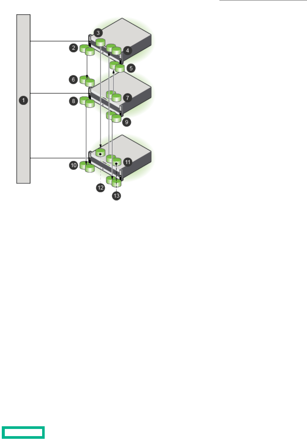
81 Multiple volumes assigned to the Outlook
volume collection
Network
2 Multiple volumes that are assigned to the
SQL volume collection 9 Multiple volumes assigned to the Temporary
volume collection
3 Single volume that is assigned to the Daily
volume collection 10 Replicas of volumes in the Outlook volume
collection
4 Replicas of the volumes in the Hourly volume
collection 11 Multiple volumes that are assigned to the
Hourly volume collection
5 Replicas of the volumes in the Datastore1
volume collection 12 Replica of volume in the Daily volume
collection
6 Replicas of the volumes in the SQL volume
collection 13 Replicas of the volumes in the Temporary
volume collection
7 Multiple volumes assigned to the Datastore1
volume collection
Replication and Folders
When you create volumes on a downstream partner, you should use a local folder. There are some differences in how folders
work with synchronous replication. Folder limit enforcement and synchronous replication are independent. Therefore, you can
perform the following actions:
• Associate one or more upstream synchronously-replicated volumes with a folder that has folder limit enforcement
• Associate one or more downstream synchronously-replicated volumes with another folder that has folder limit enforcement
Two folders can have a mix of synchronously-replicated and snapshot-replicated volumes, and folder limits can be set to
different values, because each folder is independent of the other.
You can also choose to associate only the upstream or only the downstream volumes with a folder or volumes. It is not possible
to associate both upstream and downstream volumes with the same folder, because folders are pool-scoped objects.
Replication 141
Documentation Feedback: [email protected]

Either the upstream or the downstream folder (or both) can reach the folder limit. As part of folder limit enforcement, all the
thin provisioned volumes in the folder are either taken offline or made read-only based on the performance policy associated
with them.
When an upstream, synchronously-replicated volume is taken offline, additional I/O is not accepted.
When a downstream, synchronously-replicated volume is taken offline or is made read-only, then the upstream volume goes
out of sync, but host I/O is accepted. Note that I/O resynchronization is continuously attempted by the upstream volume in
this state.
Put Incoming Replicas in a Folder
Use this command to define a partner for an array, and put incoming replicas into a folder on that array. Use the --match_folder
yes option to match the folder for the upstream volume.
Procedure
Create a replication partner, and match the upstream volume folder name with the downstream folder.
partner --create partner_name --folder folder_name --match_folder yes
Replication Seeding
If you want to replicate a snapshot collection that would take too long over a wide area network (WAN) connection, replication
seeding provides an efficient method for creating a snapshot collection to use as a temporary replica. You may need to do
this when you first add a replication partner, or if a replication partner needs to be re-initialized due to an accidental deletion
or array replacement.
The seeding process replicates a snapshot collection to a temporary array (called the seed) over a high-speed local network
(shown as 4 in the image). This third array is transported to the replication site and that same snapshot collection is then
replicated from the third array to the designated replication array (shown as 6 in the image).
Once this is completed, the seed array is removed from the system and replications between the upstream replication partner
and the downstream replication partner are enabled. From this point forward, the upstream and downstream arrays only need
to transfer changed data (shown as 5 in the image).
Replication 142
Documentation Feedback: [email protected]

41 Replication from the upstream to the seed array
(one-time)
Upstream array
2 Seed (temporary) array
5 Replication from the upstream to the downstream array
(ongoing)
3 Downstream array
6 Replication from the seed to the downstream array
(one-time)
For details about replication seeding, contact support or your sales representative.
Replica Details
Note: To view details about HPE Cloud Volumes (HPE CV), you must access the HPE CV portal.
You can view the details about an on-premises replica on the volumes page for the replica. You can tell that a particular volume
is a replica because it has a replica icon in the crumb trail at the top of the page. You can also verify that the Edit button is
disabled as are the actions in the More Actions dropdown menu. The reason for these characteristics is because the replica
is owned by the upstream group. When you access the replica from the downstream group, you can only view the replica. You
cannot edit it.
The downstream group can claim a replica if the source volume is not replicating, the replication link is broken, and the source
volume is no longer part of a volume collection. At this point, the claim option is enabled. After the replica has been claimed,
it becomes a regular volume that belongs to the downstream group and all the actions of a regular volume are enabled.
Replication Bandwidth Limits
There are two kinds of replication bandwidth limits:
• The overall limit specifies the replication bandwidth for network traffic that originates from an array to all partners
• The per-partner limit specifies the replication bandwidth for network traffic that originates from an array to a specified
partner
You can set only one replication bandwidth limit type at a time. If the overall limit is set, the per-partner limits are not allowed
for any partner. Conversely, if any partner has per-partner limits set, you cannot set an overall bandwidth limit.
Replication 143
Documentation Feedback: [email protected]

Set Overall Bandwidth Limits for Replication
If you set an overall bandwidth limit for all replications, you cannot set per-partner bandwidth throttling for each replication
partner. You can limit bandwidth by using an overall policy or per-partner limits, not both. Bandwidth limits are expressed in
megabits per second (Mbps) or kilobits per second (Kbps). The default unit is Mbps.
Procedure
Schedule overall bandwidth limits for replication.
group--create_throttle [--description text]--days days--at time--until time--bandwidth limits
Example
group --create_throttle --days Mon Wed Fri --at 06:00 --until 17:00 --bandwidth
100Mbps
Remove Overall Bandwidth Limits for Replication
If you remove overall bandwidth limits, you can create per-partner policies for each replication partner.
Procedure
Remove the overall bandwidth limits.
group--delete_throttle id
Note: Use the group --info command to see a list of throttle ID numbers.
Configure Bandwidth Limitations for a Replication Partner
Bandwidth limits are expressed in megabits per second (Mbps) or kilobits per second (Kbps). The default unit is Mbps.
Note: The following limitations apply to setting bandwidth limitations:
• You cannot set bandwidth limitations on pool partners for synchronous replication.
• If you set per-partner bandwidth throttling, you cannot set an overall bandwidth limit for all replications. You can
limit bandwidth by using an overall policy or per-partner limits, not both.
Procedure
Configure bandwidth limitations for a replication partner.
group --create_throttle [--description text] --days days --at time --until time --bandwidth limits
Example
Creating a replication bandwidth limitation of 1000 MiB that runs on Monday, Wednesday and Friday, from 6:00 AM until
5:00 PM.
$ group --create_throttle --days Mon Wed Fri --at 06:00 --until 17:00 --bandwidth
1000Mps
Modify Per-Partner Replication Bandwidth Limits
When per-partner bandwidth throttling is configured, you can easily modify the schedules. Bandwidth limits are expressed in
megabits per second (Mbps) or kilobits per second (Kbps). The default unit is Mbps.
Replication 144
Documentation Feedback: [email protected]

Procedure
Modify the per-partner replication bandwidth limits.
partner --edit_throttle partner_name [--description text] [--id number] [--days days] [--at time] [--until time]
[--bandwidth limit]
Example
Changing the bandwidth limits for partner array34.
$ partner --edit_throttle array34 --id 6 --days Mon Wed Fri --at 08:00 --until
21:00 --bandwidth 500Mbps
Replication 145
Documentation Feedback: [email protected]

Security
Security in an HPE Nimble Storage group of arrays includes several features, including role-based access control for user
accounts, encryption of data at rest, secure socket layer (SSL) certificates, and secure SMTP.
For information about access to HPE Nimble Storage arrays and volumes and user management, see Access Controls on page
20.
You control access to groups and arrays through the use of user accounts assigned to particular roles. This is known as
Role-based Access Control (RBAC). For more information on RBAC, see Role-Based Access Control on page 146.
Role-Based Access Control
Role-based Access Control (RBAC) lets you control access to groups and arrays through the use of user accounts assigned
particular roles. The role determines the level of access that a user account is provided. A user account that is assigned to the
Administrator role can create and manage accounts for other users.
All users can manage their own passwords and account information. Only users with an Administrator permission level (user
role) can add, modify, remove, enable, or disable user accounts.
For more information about permission levels (user roles), see Permission Levels on page 150.
View User Information
All users can view their own account information. Only users with Administrator permission can view the accounts of other
users.
Procedure
Type the command for a given user's information.
username --info {username}
Example
View user information for Sam:
useradmin --info Sam
Add a User Account
Each person must have a user account to access and manage an array group. Only users with Administrator permission can
add user accounts. The Administrator controls a user's access to the group by assigning a specific role to each user.
At a minimum, each user account must have a:
• username
• full name
• role
Optional. A user account can also have a:
• description
• email address
• inactivity timeout interval
You can include these options when you create the user account or you can add them later.
Security 146
Documentation Feedback: [email protected]

Procedure
1. At the command prompt, type the command to add a user account.
useradmin --add {username} --description {description text} --full_name {full name} --email_addr {valid email
address} --role {administrator | poweruser | operator | guest} --inactivity_timeout {minutes}
• The username must be alphanumeric, 1 to 32 characters, must start with a letter, no spaces. The username is required
for user login.
• (Optional) The description can have from 1 to 255 characters. No hard returns.
• The full name must be alphanumeric, 1 to 64 characters, must start with a letter, can use dashes, and apostrophes.
Underscores are not allowed.
If the full name has a space, then you must put quotation marks around the full name, for example, "Hunter Smith" Do
not use periods.
• (Optional) An inactivity timeout is specified in minutes. It cannot exceed the inactivity timeout set for the group.
2. At the command prompt, enter a new password.
{password}
The password must be comprised of alphanumeric characters with a length of 8 to 512 characters. Do not use [ ] & ; ` or
spaces. The password is required for user login.
3. Retype the new password.
{password}
Example
Adding a user account for Hunter Smith with operator access:
useradmin --add Hunter --description
This_user_has_operator_access_only.
--full_name "Hunter Smith"
--email_addr [email protected]
--role operator
--inactivity_timeout 30
Edit a User Account
You can change the full name, role, description, email address, and inactivity timeout interval with this task. You can also add
or delete a description, email address, and inactivity timeout interval with this task.
You can use the GUI to set a short interval. You do not need to use the CLI.
Note: In the GUI, the inactivity timeout interval that you set for the group is automatically applied to all user accounts.
Before you begin
You must have Administrator permission to edit a user account.
Procedure
1. Edit a user account.
useradmin --edit {username} --description {description text} --full_name {full name} --email_addr {valid email
address} --role {administrator | poweruser | operator | guest} --inactivity_timeout {minutes}
2. Verify your changes.
useradmin --info {username}
Security 147
Documentation Feedback: [email protected]

Example
Editing the user account for Hunter Smith, to change role to administrator.
useradmin --edit Hunter --description
This_user_has_operator_access_only.
--full_name "Hunter Smith"
--email_addr [email protected]
--role administrator
--inactivity_timeout 30
Change Your Account Information
All users can add, change, or delete their own description and email address. You must log in under your own username to
perform this task.
Before you begin
Procedure
Change your account information.
useradmin --edit {username} --description {description text} --email_addr {valid email address}
The description can have from 1 to 255 characters. Use underscores in place of spaces. No hard returns.
Example
Sam Jones adds a user description and updates his email address:
useradmin --edit Sam --description
This_user_has_poweruser_access.
--email_addr [email protected]
Change Your Account Password
Before you begin
All users can change their own account passwords. You must log in under your own username to change your password.
Procedure
1. Enter the commands for changing your user password.
useradmin --passwd --user {your username}
2. Type your current password.
{your current password}
3. Enter a new password comprised of alphanumeric characters with a length of 8 to 512 characters. Do not use [ ] & ; ` or
spaces.
{your new password}
4. Retype the new password.
{your new password}
Example
Sam, as the user, enters the command for a password change.
useradmin --passwd --user Sam
Security 148
Documentation Feedback: [email protected]

Reset a User Account Password
When users forget their passwords, perform this task to reset the password.
Before you begin
You must have Administrator permission to reset other users' passwords.
Procedure
1. Enter the command to reset the password for the specified user.
useradmin --passwd --user {username}
2. Type the administrator password.
{your Administrator password}
3. Enter a new password for the user comprised of alphanumeric characters with a length of 8 to 512 characters. Do not use
[ ] & ; ` or spaces.
{user's new password}
4. Retype the new password.
{user's new password}
5. Send the user the new password.
Example
Resetting the password for user Hunter Smith:
useradmin --passwd --user Hunter
Enable a User Account
You can reactivate, or enable, a previously deactivated user account.
Before you begin
You must have Administrator permission to enable user accounts.
Procedure
1. Enable an account for the specified user.
useradmin --enable {username}
2. Verify that the user account was enabled.
useradmin --list
Example
Enabling an account for user Sam Jones:
useradmin --enable Sam
Disable a User Account
If needed, you can temporarily suspend a user's access to the array.
Before you begin
You must have Administrator permission to disable user accounts.
Security 149
Documentation Feedback: [email protected]

Procedure
1. Disable the account for the specified user.
useradmin --disable {username}
2. Verify that the user account was disabled.
useradmin --list
Example
Disabling the user account for Hunter Smith:
useradmin --disable Hunter
Remove a User Account
Before you begin
You must have Administrator permission to remove user accounts.
If needed, you can permanently remove a user account. Consider disabling the account rather than removing it.
Procedure
1. Remove the account of the specified user.
useradmin --remove {username}
2. Verify that the account was removed.
useradmin --list
Example
Removing the user account for Hunter Smith:
useradmin --remove Hunter
Permission Levels
Each feature has a minimum permission level (user role) that is required to use the feature.
The permission levels (user roles) are summarized here.
Table 11: Summary of Permission Levels (User Roles) and Access
AccessPermission Level (User Role)
All actionsAdministrator
All actions except user management, inactivity timeout, array setup, and array
resetup
Power User
Management actions except to delete or remove dataOperator
View information and choose VMware subnetsGuest
The following table explains the methods of user access control.
Security 150
Documentation Feedback: [email protected]

Table 12: How Nimble Interfaces Manage Access
Method of User Access ControlInterface
Disables or hides unauthorized actions.GUI
Ignores unauthorized actions and returns a Permission denied message.CLI
The following table lists individual array unit-cs features, the actions associated with each feature, and the minimum permission
level (user role) required to perform the action.
Table 13: Features, Actions, and Permission Levels (User Roles)
Minimum Permission Level (User Role)ActionFeature
GuestList / view infoAlerts
Power UserTest
GuestList / view infoArrays
Power UserDiscover
Power UserEdit array name
AdministratorSet up / Re-set up
Power UserAdd
Power UserRemove
Power UserReboot
Power UserShut down (halt)
Power UserFail over controllers
AdministratorRegenerateCertificates
OperatorList / view infoCHAP user
OperatorCreate
OperatorDelete
OperatorEdit
GuestList / view infoControllers
Power UserReboot
Power UserFail over
GuestView (local or UTC time)Date and Time
Power UserEdit
GuestList / view infoDisks
Power UserAdd
Power UserRemove
Power UserEnable / disableDNA
Power UserSet secure tunnel
Power UserSet HTTP proxy
Security 151
Documentation Feedback: [email protected]

Minimum Permission Level (User Role)ActionFeature
GuestList / view infoDomain name / DNS server for a group
Power UserAdd
GuestList / view infoExpansion shelves
Power UserAdd
Power UserActivate
GuestList / view infoFibre Channel interfaces
Power UserEdit
Power UserUpdate configuration
GuestList / view infoGroups
GuestList limits
AdministratorEdit inactivity timeout
Power UserEdit other settings
AdministratorMerge
Power UserCreate throttle
Power UserEdit throttle
Power UserDelete throttle
Power UserInitiate DNA
Power UserValidate DNA
Power UserUnset HTTP proxy
Power UserReboot
Power UserShut down (halt)
GuestShow the online helpHelp
OperatorList / view infoInitiator groups
OperatorCreate
OperatorDelete
OperatorEdit
OperatorAdd initiator
OperatorRemove initiator
OperatorAdd subnet
OperatorRemove subnet
GuestList / view infoIP addresses
Power UserAdd
Power UserEdit
Power UserDelete
Security 152
Documentation Feedback: [email protected]

Minimum Permission Level (User Role)ActionFeature
Power UserServer IP addressiSNS server for a group
Power UserPort number
Power UserEnable / disable
GuestList / view infoMigrations
GuestList / view infoNetwork configurations
Power UserCreate a draft
Power UserDelete
Power UserValidate
Power UserActivate
Power UserEdit
GuestList / view infoNetwork interface cards (NICs)
Power UserEdit
Power UserAssign / unassign a subnet
GuestList / view infoNTP server for a group
Power UserAdd
GuestList / view infoPerformance policies
OperatorCreate
Power UserDelete
OperatorEdit
GuestList / view infoPools
Power UserCreate
Power UserDelete
Power UserEdit
Power UserAssign / unassign array
Power UserMerge
GuestList / view infoProtection templates
OperatorCreate
OperatorEdit
OperatorDelete
OperatorAdd a schedule
OperatorEdit a schedule
OperatorDelete a schedule
Security 153
Documentation Feedback: [email protected]

Minimum Permission Level (User Role)ActionFeature
GuestList / view infoReplication partners
Power UserCreate
Power UserDelete
Power UserEdit
OperatorCreate / edit / delete QoS policy (throt-
tle) settings
OperatorPause / resume replication
OperatorTest connection
GuestList / view infoRoutes
Power UserAdd
Power UserEdit
Power UserDelete
GuestList / view infoSnapshots
Power UserDelete
OperatorEdit
OperatorSet online / offline
GuestList / view infoSnapshot collections
Power UserDelete
OperatorEdit
Power UserEdit community stringSNMP for a group
Power UserEnable / disable gets
Power UserEdit responder port number
Power UserEdit system contact / location
Power UserEdit trap host IP address
Power UserEdit trap port number
Power UserEnable / disable traps
GuestList / view infoSoftware
Power UserDownload
Power UserPre-check
Power UserUpdate / upload
Power UserResume an update
Power UserVolume reserveSpace reservations, default for a group
Power UserVolume limit
Security 154
Documentation Feedback: [email protected]
Minimum Permission Level (User Role)ActionFeature
AdministratorList / view infoSSH keys
AdministratorAdd
AdministratorEdit
AdministratorDelete
GuestDisplayStatistics
GuestList / view infoSubnets
Power UserAdd
Power UserEdit
Power UserRemove
GuestList / view infoTime zone
Power UserChange
GuestView own profileUser accounts, individual
GuestChange own password / email address
AdministratorList / view infoUser administration
AdministratorAdd users
AdministratorChange passwords
AdministratorEdit user permissions
AdministratorEdit timeout interval
AdministratorEnable / disable users
AdministratorRemove users
GuestList / view own infoUser sessions
AdministratorList / view info for other users
GuestListVMware plugins
GuestSubnet, choose
Power UserRegister / Unregister
Security 155
Documentation Feedback: [email protected]

Minimum Permission Level (User Role)ActionFeature
GuestList / view infoVolumes
OperatorCreate
Power UserDelete
Power UserEdit volume size
OperatorEdit other volume settings
OperatorCreate / edit / delete ACLs
OperatorSet online
Power UserSet offline
OperatorTake snapshot
Power UserRestore from snapshot
OperatorClone from snapshot
OperatorAssociate with volume collection
OperatorDisassociate from volume collection
Power UserClaim partner volume
Power UserMove to another pool
GuestList / view infoVolume collections
OperatorCreate
Power UserDelete
OperatorEdit
OperatorValidate
OperatorAdd schedule
OperatorEdit schedule
OperatorDelete schedule
OperatorTake snapshot
Power UserRestore from snapshot
Power UserPromote
Power UserDemote
Power UserHand over
Power UserStop replication
Access Control with Active Directory
An Active Directory domain is a collection of objects within a Microsoft Active Directory network. The objects in the domain
can include a single user, a group, or a hardware component, such as a computer or printer. Each domain contains a database
that stores identity information about the object.
Security 156
Documentation Feedback: [email protected]

Active Directory relies on mapping Active Directory groups to array roles to determine a user's access. Users are assigned to
particular Active Directory groups which are designated with specific array roles. The array roles indicate the level of access
permissions that the group members have to perform particular functions.
Note: Active Directory on an HPE array can support up to 100 groups per array with up to 2000 Active Directory
users logged in at one time. If you exceed 2000 users, the session for the user who has been logged into the system
the longest is terminated.
View Information about the Active Directory Domain
You can use the userauth --info command to view Active Directory domain metadata like the connection status, the
organizational unit, and more.
Procedure
List the details about the Active Directory domain.
userauth --info domain_name domain_name
The details are displayed in a list as follows:
Active Directory Domain Name : <domain_name>
Organizational Unit : <ou>
Computer name : <computer_name>
Netbios : <netbios>
Status : <status>
Guidelines for Working with Arrays and Active Directory
You can join an array to an Active Directory domain. The following list includes some guidelines to consider when working
with arrays and Active Directory.
• When you add an Active Directory user to a group that is authorized to log into the array, you must use the same username
and password with the array that you use with all other AD-connected systems in the environment.
• Disabling a user's Active Directory account also disables that user's access to the storage environment.
• Joining an array to a domain creates an Active Directory account for the array on Active Directory. The default Organizational
Unit (OU) for the account is Computers. You can create the account under a different OU.
• The default name of the computer account is the first 15 characters of the array group name. You can specify a different
computer name if you choose.
If you use the default name, you must make sure that the first 15 characters of the array group name do not conflict with
any other array group name that is in Active Directory. If you duplicate a group name, Active Directory removes the first
version of the group name so that the new group name can join Active Directory. Consequently, the group with the
duplicated name will not be able to log into the array even though it joined Active Directory first.
Example:
1 group-array-xxxx1 was the first group to join the Active Directory domain ZZZ. The default AD machine account name
for the array is group-array-xxx because the group name truncates after the first 15 characters.
2 group-array-xxxx2 was the second group to join the Active Directory domain ZZZ but the default AD machine account
name would also be group-array-xxx because the group name truncates after the first 15 characters.
3 Upon joining the AD domain, group-array-xxxx2 replaces the AD machine account from group-array-xxxx1 with an
account for group-array-xxxx2. Group users are no longer able to log into group-array-xxxx1, although they can now
log into group-array-xxxx2, which joined later.
• Avoid using special characters in OU and Group names. If you use special characters, they must be preceded by a single
backlash, and the entire argument must be inside either single quotation marks (') or double quotation marks ("). For a list
of special characters, refer to the Reserved Characters table in Distinguished Names.
Security 157
Documentation Feedback: [email protected]

• Active Directory administrators can create an account for the array in any OU and then can give storage administrators
the privilege to join the domain.
• After an array has joined a domain, you can enable and disable Active Directory authentication without leaving the domain.
Join an Active Directory Domain
Before you begin
You must be a local user with administrative privileges to join an array to an Active Directory domain.
Procedure
1. Join the Active Directory domain.
userauth --join domain_name --domain_user domain [--ou ou_name] [--computer_name computer_name] [--netbios_name
netbios_name]
2. Enter the password at the prompt.
3. (Optional) To verify that the array was added to the Active Directory domain, run the --list command.
Leave an Active Directory Domain
Important: If you leave the domain, all users from that domain lose access to the array and might receive a error
message.
Procedure
1. Leave an Active Directory domain to remove access to the Active Directory domain account.
userauth --leave --domain_user domain_user_name [--force]
Note: If you specify force, any error on Active Directory is ignored.
2. Enter the password at the prompt.
3. (Optional) To verify that the array is no longer on the Active Directory domain, run the --list command.
User Authentication and Logon
Active Directory supports the following types of user names for authentication.
• User_name (Authenticate with the default domain or as a local user)
• DefaultDomain\User_name (Authenticate with the default domain)
• TrustedDomain\User_name (Authenticate with the trusted domain)
Authentication uses the following guidelines:
• If you are authenticating using Active Directory, do not add a group to an array with the group type "Distribution."
• If the array is not a member of an Active Directory domain, then users are authenticated locally on the array. The account
must have been created on the array in the Administration: Users and Groups dialog.
• If you try to authenticate to an array that is a member of an Active Directory domain, you are authenticated against the
Active Directory first.
Note: Some built-in users, such as root, admin, and nsupport, are always authenticated locally.
If authentication to Active Directory fails for reasons other than a password failure, the array attempts to authenticate the
user locally. If the local account experiences a password failure or the account does not exist locally, authentication fails.
• You can enter a username or a combination of DOMAIN\username. If you do not include DOMAIN, the authentication effort
uses the default domain; that is, the domain that the array is a member of.
• The number of repeated failed login attempts allowed depends on the Password lockout setting.
Security 158
Documentation Feedback: [email protected]
• A successful login provides you with the GUI and CLI roles and capabilities as defined by the group.
• If you lose access to the array, the system response depends on whether you are logged in locally or as an Active Directory
user. You might receive an error message, or you might be logged out of the array.
• When a user is removed from an Active Directory group that has access to the array, the user is no longer able to log
into the array. Existing login sessions will continue until the user logs out. This is consistent with the behavior of
Windows clients and group memberships.
• After an Active Directory group is removed from the array, users can no longer log into the group. Existing login
sessions will continue until the users log out.
Enable Active Directory Domain Authentication
By default, authentication is enabled after you join the domain. You do not have to enable the Active Directory domain unless
it was disabled previously.
Procedure
Enable Active Directory domain authentication on an array.
userauth --enable domain_name
The command fails if the status of Active Directory authentication is already in the requested state.
Disable Active Directory Domain Authentication
Important: When Active Directory domain authentication is disabled, users who belong to the Active Directory
domain can no longer access the array. For users who are already logged in to the array, any new operation results
in an error.
Procedure
Disable the Active Directory domain.
userauth --disable domain_name
Active Directory Groups
To use the Active Directory, Active Directory group names must be associated with array user roles. Each Active Directory
group can have only one of the following roles assigned to it:
• Administrator
• PowerUser
• Operator
• Guest
If the user belongs to a group that is not associated with any role or if the group is disabled, the user will not be able to login
to the array.
If a user belongs to multiple Active Directory groups which have different roles, each time the user executes a CLI command,
the group-role mapping with the most restrictive role (the role with the least privileges) is used.
When an administrator makes a change to the group-based RBAC rules, users who are logging in will use the updated roles.
For users who are already logged in, they will receive the new privileges for any subsequent operation.
Rules for Array Group Names on the Active Directory
You might want to plan the groups that you want to create on the Active Directory beforehand because group names cannot
be changed after the group is created.
It is not recommended that you use special characters in group names.
Security 159
Documentation Feedback: [email protected]

Note: If you try to add a group (from systems prior to Windows 2000) with a name that contains special characters,
the special characters are replaced with underscores (_). Whenever you use that group name, you must use the version
of the group name that includes the underscores. The group name that contains special characters is not valid.
You must log in to the array using the pre-Windows 2000 logon name that is shown in the Account tab of the Active Directory
server user property page.
Mapping a Group to a Role
To add a group to an Active Directory domain, you must map an Active Directory group to a specific role.
If the user belongs to a group that is not associated with any role or if the group is disabled, the user will not be able to login
to the array
Note: For users of systems prior to Windows 2000: If you try to add a group with a name that contains special
characters, the special characters are replaced with underscores (_). Whenever you use that group name, you must
use the version of the group name that includes the underscores. The group name that contains special characters
is not valid.
Procedure
1. Map a group to a particular role.
userauth --add_group group_name --domain domain_name [--role role] [ --description description] [--inactivity_timeout
minutes]
If the role is not specified, the guest role is assigned to the array group.
If the inactivity_timeout is omitted, the inactivity timeout for the array group is used.
2. Run the following command to verify that the process completed successfully.
userauth --list_group --domain domain_name
Enable an Active Directory Group
Procedure
Enable the Active Directory group.
userauth --enable_group group_name --domain domain_name
Remove an Active Directory Group
Note: After a group is removed from the array, users can continue to log into the group and perform actions for
approximately five minutes. After five minutes, the user can no longer access the group.
Procedure
1. Remove a group from the Active Directory domain.
userauth --remove_group group_name --domain domain_name
2. (Optional) Verify that the group was dissociated from the role.
userauth --info domain_name
Disable an Active Directory Group
Note: If a group is disabled then users will not be able to log in to Active Directory.
Security 160
Documentation Feedback: [email protected]

Procedure
Disable the Active Directory group.
userauth --disable_group group_name --domain domain_name
Edit Active Directory Group Information
You can edit the following information in an Active Directory group:
• Group role
• Group description
• Inactivity timeout
Note: If the group name is changed, you must remove the group mapping on the array and add a new group mapping
with the new group name.
Procedure
Edit the Active Directory group.
Note: You cannot change an Active Directory group name after the group is created.
userauth --edit_group group_name --domain domain_name [--role role] [--description description] [--inactivity_timeout
minutes]
Troubleshooting the Active Directory
When you have issues with your array on the Active Directory, you can run some of the following commands to try to fix the
issue.
FunctionCommand String
Tests whether the group exists in the Active
Directory domain
userauth --test_group group_name -- domain domain_name
Tests whether the user belongs to the Active
Directory domain
userauth --test_user user_name -- domain domain_name
Provides view of the current Active Directory
status
userauth --info
If you make any changes on the Active Direc-
tory server that are related to the Active Di-
rectory configuration on the array, you might
need to disable Active Directory authentica-
tion and re-enable it to clean up the cache.
userauth --disable domain_name
userauth --enable domain_name
For complete syntax on these commands, refer to the Nimble Storage Command Reference.
CHAP Authentication
As the name implies, Challenge-Handshake Authentication Protocol (CHAP) uses a challenge-response mechanism to
authenticate iSCSI initiators. A shared "secret," or password, let the system verify that the iSCSI initiator is who it claims to be
and is authorized to access the volume.
Before you can use CHAP authentication, set up the CHAP secret on the volume and on the iSCSI initiator. CHAP secrets must
be between 12 and 16 characters long. For the best security, the secret should be random letters and numbers, not a word
Security 161
Documentation Feedback: [email protected]

that could be guessed. If your iSCSI initiator imposes further restrictions on the CHAP secret, you must adhere to these stricter
regulations.
When creating a CHAP secret, adhere to the strictest regulations: 12-16 characters containing no spaces or the special
characters ( ' " ` ). The CHAP user name should not contain characters such as : ~ ! @ # $ ^ & ( ) + [ ] {} * ; : ' " ., % | < > ? / \ =
`.
Create a CHAP Account
CHAP (Challenge Handshake Authentication Protocol) users share a "secret." This CHAP secret is a word, phrase, or series of
characters that both the array and the initiator know. The array will only allow access to those iSCSI initiators who respond
with the correct secret.
Procedure
Create a CHAP user
chapuser [--create name] [--password shared_password]
Assign a CHAP User to a Volume
The CHAP user must be created before it can be assigned to a volume. Multiple volumes can be assigned to the same CHAP
user.
Procedure
Assign a CHAP user. Specify whether to add the ACL to a volume, a snapshot, or both.
vol --addacl volume_name
Modify a CHAP User
For increased security, you may want to change the CHAP secret at regular intervals, or if you suspect that an unauthorized
computer has accidentally gained access to the array.
Note: If you change a CHAP secret, all volumes protected with this CHAP account will be inaccessible until the
corresponding iSCSI connections are changed and synchronize with the new CHAP secret. Consider then when you
determine what time to make these changes.
Procedure
Edit CHAP user information. Enter at least one parameter to be changed (name, description, or password).
chapuser [--edit name]
Delete a CHAP User
Delete CHAP users that are no longer needed.
Procedure
Delete a CHAP user.
chapuser --delete name
Login Banner
By default, a login banner displays in the CLI interface for all controllers in an array group. However, the banner can be
configured to not be displayed (deleted). It can also be configured to be displayed either before prompting for user's credentials,
or after user authentication. By default, the login banner is displayed after user authentication.
Security 162
Documentation Feedback: [email protected]

Important: You must have Administrator privileges to configure the login banner.
The login banner has a factory default login banner message, but the message can be edited to suit your specific requirements.
The message is restricted to 2,048 ASCII printable characters with support for newline. International characters are not
supported. (The official Department of Defense [DoD] banner character count is about 1,200 characters.) An edited banner
message can be reset to the factory default message.
Edit the Login Banner
Before you begin
Ensure that you have Administrator privileges.
Procedure
1. Enter the following command to edit the login banner.
group --edit [--login_banner] [--login_banner_after_auth {yes | no}] [--force]
2. After you type the command and press Enter, type the banner message, then type ctrl + D to save the message.
Note: The login banner will be deleted if you create an empty banner message (no characters typed). To delete
the login banner use the --force option when entering the command.
Example
Editing the login banner message and setting the login banner to be displayed before user authentication.
$ group --edit --login_banner --login_banner_after_auth no
Please enter the banner message below followed by ^D:
***********************************************
* *
* SECURITY WARNING: AUTHORIZED PERSONNEL ONLY *
* *
***********************************************
$
Deleting a login banner
$ group --edit --login_banner -force
Please enter the banner message below followed by ^D:
$
Show the Login Banner
Procedure
Enter the following command to show the login banner.
group --show_login_banner
Example
Showing the login banner.
$ group --show_login_banner
USAGE WARNING
This is a private system. This system is provided only for authorized use.
Unauthorized or improper use of this system may result in civil claims
and/or criminal charges. The array owner may monitor the system for all
Security 163
Documentation Feedback: [email protected]

lawful purposes, including but not limited to ensuring that access is
authorized and for other security reasons. Use of this system constitutes
consent to the array owner for monitoring of this system.
Administrators should ensure that this system is protected by a firewall
and implements all security procedures itemized in the documentation.
$
Reset the Login Banner
Procedure
1. Enter the following command to reset the login banner message to the factory default message.
group --reset_login_banner
2. (Optional) Verify that the login banner message has been reset to the factory default message
group --show_login_banner
Example
Resetting a custom login banner message to the factory default message
$ group --show_login_banner
***********************************************
* *
* SECURITY WARNING: AUTHORIZED PERSONNEL ONLY *
* *
***********************************************
$ group --reset_login_banner
$ group --show_login_banner
USAGE WARNING
This is a private system. This system is provided only for authorized use.
Unauthorized or improper use of this system may result in civil claims
and/or criminal charges. The array owner may monitor the system for all
lawful purposes, including but not limited to ensuring that access is
authorized and for other security reasons. Use of this system constitutes
consent to the array owner for monitoring of this system.
Administrators should ensure that this system is protected by a firewall
and implements all security procedures itemized in the documentation.
$
Encryption of Data at Rest
You can enable encryption at the group level or at the volume level as required for each group of arrays in your environment.
Before you can create encrypted volumes, you must perform an initialization step that creates the master key. The master
key protects the keys that are used to encrypt volume data. The master key is protected by a passphrase that is specified
when creating the master key. At times, it will be necessary to enter the passphrase to enable access to encrypted volumes.
The encryption state of a volume is established when the volume is created, and cannot be changed afterward. Cloned volumes
inherit the encryption state of their parent. The group configuration contains a default encryption default setting, where you
can either enable or disable AES-256-XTS encryption. (The AES-256-XTS encryption algorithm is specifically designed for
use in encrypting block storage.) The group configuration also contains an encryption scope setting, which specifies where
and how to apply the encryption default setting. You can force the encryption default setting to be applied to all new volumes
in the group, or allow overriding the encryption default setting on a per-volume basis.
The group configuration contains an encryption mode setting that defines behavior on system restarts. The value can be set
to "secure" or "available." In secure mode, the encryption passphrase must be entered every time the group leader array is
Security 164
Documentation Feedback: [email protected]

restarted to unlock the master key. In most cases, available mode stores enough information in non-volatile memory to recover
the master key without entering the passphrase. The information is not stored on disk. Available mode is provided for
convenience in situations where the physical security of the array is unlikely to be compromised.
Important: Even though available mode significantly reduces the number of times you must enter a passphrase when
a group leader array restarts, it does not guarantee that you will never have to enter a passphrase after a restart.
There are certain scenarios where you would still have to specify a passphrase while in available mode to access
encrypted data, including:
• Controller upgrade: If array controllers are being upgraded to a newer model, you must enter a passphrase. While
data is recovered from the non-volatile memory, access to encrypted volumes is not.
• NVRAM loss: In the rare case where non-volatile memory (NVRAM) is lost, you must enter a passphrase to access
encrypted volumes. Older arrays (CS2xx and CS4xx series) that remain powered off for a long time could lose
NVRAM as a result of battery discharge.
CAUTION:
• If you lose the passphrase for the master key or access to the external key manager, data in encrypted volumes
cannot be retrieved. Store the passphrase in a secure, accessible place.
• If your encryption requirement changes after creating a volume, you cannot change its encryption status. You
can create a new volume with the encryption status that you need, and migrate the data to the new volume.
• Performance might be slow when accessing encrypted volumes from the CS210 or CS215; however the performance
impact due to encryption will be less severe on the CS235 arrays.
Enable Encryption
Beginning with version 6.0, you have the option of using a passphrase for local key management or using external key
management for your encryption keys. The use of encryption involves using keys to encrypt volume data. Two important
points to remember are:
• If you lose the passphrase for the master encryption key or if you lose access to the external key manager, data in the
encrypted volumes cannot be retrieved.
• Once it has been set, the encryption status of a volume cannot be changed.
Before you begin
You must have Administrator privileges to change the encryption configuration.
To ensure that you are aware of the requirements for encrypting volumes, read the information in Encryption of Data at Rest
on page 164.
Procedure
1. Create the master key or set up the external key manager.
encryptkey --create_master
2. Enter a new passphrase composed of any printable characters with a length of between 8 and 64 characters.
3. Retype the new passphrase.
4. (Optional) Specify the group encryption settings.
group --edit --encryption_cipher {aes-256-xts | none} --encryption_scope {group | volume} --encryption_mode {available
| secure}
The group encryption settings are applied to the volumes that you create from this point forward. The settings are not
applied to existing volumes.
5. Create a volume using the encryption settings that you need and that are valid based on the group encryption settings.
vol --create volume_name --size mebibytes --encryption_cipher {aes-256-xts | none}
Security 165
Documentation Feedback: [email protected]

Note: After volume creation, encryption on that volume cannot be changed.
Example
Enabling encryption using the default group encryption settings (encryption_cipher = aes-256-xts, encryption_scope = group,
and encryption_mode = available). Here you have the option of using the encryptkey --create_master command to enable
encryption with local key management or setting up an external key manager as described in the next section.
$ encryptkey --create_master
Enter new passphrase:
Retype new passphrase:
Creating a volume with encryption when encryption is enabled for the group.
$ vol --create finance --size 1000000 --encryption_cipher aes-256-xts
Creating an unencrypted volume when encryption is enabled for the group.
$ group --edit --encryption_scope volume
$ vol --create facilities --size 500000 --encryption_cipher none
Secure Sockets Layer Certificates
To establish a secure connection with a website or other server, the server presents a certificate to authenticate its identity.
Certificates are an important component of Secure Sockets Layer (SSL) because they prevent others from impersonating a
secure website or server.
The following types of certificates are supported:.
• Array certificate chain: Generated when the array is first started.
• Group certificate chain: Generated when the array is configured as a group leader.
• Custom certificate chain: (SSL Certificate) Either a self-signed certificate or a certificate generated by exporting the
Certificate Signing Request (CSR) and then signing and importing the root certificate authority (CA) and signed certificates.
This is the most secure type of certificate.
An SSL certificate is an electronic document that verifies ownership of a public key and ensures the identity of your server,
which provides greater security of online interactions. The certificate includes the following information:
• Information about the key
• The identity of its owner
The digital signature verifies that a trusted third party (the CA ) has authenticated the identity of the organization that owns
the key and has verified that the contents of the certificate are correct.
If the signature is valid, and the person examining the certificate trusts the signer, then they know that it is safe to use that
key to communicate with its owner.
To get an SSL certificate, you must create a Certificate Signing Request (CSR). Then, you send the CSR data file to the CA
and the response that you receive from the CA is your SSL certificate. This SSL certificate is the intermediate chain public key
and you import the key through the GUI or CLI.
After you receive the certificate and install it on your server, the identity of your server can be authenticated.
You can also import a trusted certificate.
Create and Import a Custom Certificate or Certificate Signing Request
You can use the GUI to generate a self-signed certificate or a certificate signing request (CSR). You can then import a certificate
authority (CA) signed custom certificate.
Security 166
Documentation Feedback: [email protected]

Note: If you already have a custom certificate and you add another one, the add operation becomes a replace operation
and replaces your current custom certificate.
Procedure
1. From the GUI, select Administration > Security > SSL Certificate.
2. From the SSL Certificates and Signing Request page, click the plus (+) icon to add a certificate.
3. Under Certificate Actions, use the drop-down list to select the operation you want to perform.
The list provides you with the following options:
1 Generate a self-signed custom certificate
2 Generate a certificate signing request (CSR)
3 Install a CA (certificate authority) signed certificate
4 Import a trusted certificate
5 Install a custom PKCS12 bundle.
Note: The array supports only RSA certificates. If your PKCS12 bundle does not contain an RSA private key,
generate a new PKCS#12 file using an RSA private key.
4. Enter the required information.
For the first two options in the Step 3 list, you can provide the following:
• The certificate information including the number of days the certificate will be valid
• The FQDN list
• The IP address
Note: If you do not specify values for these fields, then the default values are used to generate the CSR or
self-signed custom certificate.
For the third option, You must paste in the CA Certificate chain and the signed certificate. Use PEM format for this
information.
For the fourth option, enter the name of the certificate and check the button that specifies the method you want to use
to provide the certificate chain.
For the last option, use the Choose File browse option to locate the PKCS12 bundle. You can enter a password; however,
you can create a bundle without a password and import it. For security purposes, it is a good practice to always create the
bundle with a password.
Note: The file that you upload must contain the entire certificate chain. If it does not, an error occurs.
5. Select Save.
Delete a Certificate
You can only delete a custom certificate because the array and group certificates are automatically generated.
Before you begin
You must have a custom certificate installed on your server.
Procedure
1. Delete a custom certificate.
cert --delete custom
2. (Optional) Enter the following command to verify that the certificate was deleted.
Security 167
Documentation Feedback: [email protected]

cert --list
Create a Custom Certificate Chain
To verify that the array can trust the certificate, you must present the entire chain of certificate authorities the array. The
certificate chain must include the root certificate and every subordinate certificate (there might be more than one subordinate
certificate).
Before you begin
It is important that you paste each subordinate certificate into the certificate chain in order.
Procedure
1. Gather your certificates from each CA server in the chain.
2. Open the root CA certificate as a text file.
3. Copy the contents of the root CA certificate into notepad.
Make sure to include the begin certificate tags and the end certificate tags for each certificate.
-----BEGIN CERTIFICATE-----
-----END CERTIFICATE-----
4. After the last line of the root CA certificate, enter a carrige return.
5. Paste the contents of the first subordinate CA certificate.
6. After the last line of the first subordinate CA certificate, enter a carrige return.
7. Repeat steps 5 and 6 for each additional subordinate CA certificate.
This example shows one root CA certificate and one subordinate CA certificate. Your certificate chain might include more
than one subordinate CA.
-----BEGIN CERTIFICATE-----
MIIGXjCCBEagAwIBAgIQZe4IxsgABbZCTj2L0apZATANBgkqhkiG9w0BAQsFADBS
MRUwEwYKCZImiZPyLGQBGRYFbG9jYWwxFjAUBgoJkiaJk/IsZAEZFgZjYXJzb24x
ITAfBgNVBAMTGGNhcnNvbi1UQ0FSU09OLVJPT1RDQS1DQTAeFw0xNzEwMjYxMjE1
MTFaFw0xOTEwMjYxMjI1MDlaMFIxFTATBgoJkiaJk/IsZAEZFgVsb2NhbDEWMBQG
CgmSJomT8ixkARkWBmNhcnNvbjEhMB8GA1UEAxMYY2Fyc29uLVRDQVJTT04tUk9P
VENBLUNBMIICIjANBgkqhkiG9w0BAQEFAAOCAg8AMIICCgKCAgEAzL+9d87ypqEo
rqSmcqXLRy1/rcLFVE5ozxPI1vfwUqLaLQC6SKPow6xD0ZQrvtryehrZQ91sjsSr
9bx/7f9NloMRTeRzEoH2wv0rfUijGV78B2lNMYPqIxmTOeefKE9DIlWDyT3R1kaj
RFrbuJFVCJVCfS2Jwrw8FQ56AzL9CbEFXYi4ITCNdd4ZsICll6Qwxg+8scVFFCta
527TXQB6wfCtomk4FW94/q//TgPLbuO/RwwMTkEaAa2Nipl+qLAh3rpTvrprGAtj
A7fAeEdrcK3hPlDz9rRqTL24xd6qh5MaUNCZhxxLZg3auu6FPcSz5ykoGD81QwaE
nC8wFbDJE6/5HdbAtboxIg+HelhT6rsp0b0AzVPglM47pHNC37MUlFD1qBO+pA+d
5Ox0Lj9/I1xrVSHBHESu0cYWqtQN728WPg4ZxivL7jzo3RyCwp+9Nw6JzxwBzLdz
MiDShVYB+A6nwppOCopxXhistrOweGhflucmz++bq1KrH7DsNa5gmGGWTMytWaYB
QKe5EDVQaK9i63fzBhNWaZiSYJhRZRGNOYmY/VOwhFlSR6jjcwOnnWhWM3NnkdSG
fT18mpclqbhFX8FIlyXyazqCmVCd8e3urpHzI10x6JJMQStqj4APF7qsEXWW46vJ
hjAPBgNVHRMBAf8EBTADAQH/MB0GA1UdDgQWBBT0ePFtg+E4caBFCkvHsbFklaRp
Security 168
Documentation Feedback: [email protected]

xzASBgkrBgEEAYI3FQEEBQIDAQABMIGxBgNVHR8EgakwgaYwgaOggaCggZ2GT2Zp
bGU6Ly8vL3RjYXJzb24tcm9vdGNhLmNhcnNvbi5sb2NhbC9DZXJ0RW5yb2xsL2Nh
cnNvbi1UQ0FSU09OLVJPT1RDQS1DQSgxKS5jcmyGSmh0dHA6Ly90Y2Fyc29uLXN1
YmNhLmNhcnNvbi5sb2NhbC9jZXJ0ZGF0YS9jYXJzb24tVENBUlNPTi1ST09UQ0Et
Q0EoMSkuY3JsMCMGCSsGAQQBgjcVAgQWBBTtwFmmGeyZ0Ap+0bJUol08Ul6xyz
BgkqhkiG9w0BAQsFAAOCAgEAdcgfjxG+dj0Frw0x9vCPaCHwsP31qA/br7VRQQXE
p9xQ96xvO7gyn/UNqApxI3Jlb11m5S0pJC1QcHt6s6HvVrDaNJTQCpTn57qrIM/t
zOCExe1u5qvEE0l7ruk93e10EjTrDh1NZ5YSyMyButxWzSYevQz9c/j4SKxPms7P
GTTNvCXQrzVPZ2Olhwz7jKw63CnmLjMZvwcXU1++mp0W1lCdlUwDW6JoZqdHk6Pn
h19tI2jHGEuaoXy28dhFaA9vslCYswE0oT8w1svJSYTWPqUZhnZc60N75LWfPVHA
pM1COjGiVo3bezYpWUhMliCsnLx33w5mkmoIkReU27+x1aE5CG0cpeXWd1KoGU7k
YkqyTpFVy2hnDipbAuumgGmlR88kV0yOZZkGT9Oje9oV/hanyO68VMVkklegY5kp
A6n66hJIGg3rUWIVIQArHOsaPnml5I3n06Yt04SPNG8S6Pq0BZDbQ8nNjLRCpNMq
gRHgStXsZzcxna3QQvcdCzLe5H2xo3bf90lZD6firaOQkO1MSDZn6CvGhcFn8fZH
n8xWKRJjC8ppOaSvKCcvSBulXcuQEf6CE3QMhDxXUUbWxj2mkzMljYFv7dIhWD9R
x7/4Y42HzDaGh+g6QQzSlx9tYsltx0Fl7BKBWI4D7PqcsO3eTKze+TWoks1Cj6b1
BtOotfVPbJR59MPQV7typNgpLAWHoY8CAwEAAaOCAS4wggEqMAsGA1UdDwQEAwIB
1hw=
-----END CERTIFICATE-----
-----BEGIN CERTIFICATE-----
MIIHmzCCBYOgAwIBAgITYgAAAAiI2D6wVb9OUAABAAAACDANBgkqhkiG9w0BAQsF
ADBSMRUwEwYKCZImiZPyLGQBGRYFbG9jYWwxFjAUBgoJkiaJk/IsZAEZFgZjYXJz
b24xITAfBgNVBAMTGGNhcnNvbi1UQ0FSU09OLVJPT1RDQS1DQTAeFw0xNzEwMjYx
MjE4MjBaFw0xODEwMjYxMjI4MjBaMFExFTATBgoJkiaJk/IsZAEZFgVsb2NhbDEW
MBQGCgmSJomT8ixkARkWBmNhcnNvbjEgMB4GA1UEAxMXY2Fyc29uLVRDQVJTT04t
U1VCQ0EtQ0EwggIiMA0GCSqGSIb3DQEBAQUAA4ICDwAwggIKAoICAQCs/ZyVt26L
I4aalhaCJeIaw9ESUN8mfoqC7S5OY1eLFH3u8y2cLXgs1DRi8Qbh9/E23++zHk+1
v+L0eGTeQVDNqEEHl5o4mSwrZxfZw/HNOrHWVZcbLcxrbhQQeQxyAO8Jxys4tiaf
cKvRAiJMmpiByn16TAmDxj/tUKd3Ggr70i5rYv1VSgM6e4wtXtPvYYYwVyriFt4e
GbJAjKDjZLkgf/bKhiZjTCEvQzdz1RjFGe975mxGtrdY9sE1P/iaQekKVFQp76p0
3oUvpQRW8INA++2dYb69RdazkD82etPzdY+XXLvF3PdSKIvNz2WXfrfoJRIjlXJ2
qR30UWjwvRn8vAnaZeU8cS9Bv0ikWGNzONuGPe/4q4TmN4NMX2/wIRtBN3XHDx
6EIQDt+ks3QJdq/mNmF0WFNwq6gkN53JR/H1WPDXWoRTIbFH/6kzST5MXTQA4gUF
Uu9vycpn7w91pgiWLZHN0m8FqHF0Uf4hSHoGxr0AUs/oV5yXGa/sC0YbK8EZmvlg
SXgt1sYRNqV8TFt4F/JjPjqwobQTvClBvd2l4oM1l0pjqSU28vASbvyUbA1Gl7GR
jEvYXB8B531zHJKIu0dy6JstNpbwDqzdOTUvJQvVqThRU5NKXsa3O/jRM0PMK/Sx
jzSfhBrX+5PQBm3WhuDw4LkVwk7HUigdvwIDAQABo4ICaTCCAmUwEgYJKwYBBA
NxUBBAUCAwEAATAjBgkrBgEEAYI3FQIEFgQULcg+TBDHgDtkggANblRuzdYt49kw
Security 169
Documentation Feedback: [email protected]

HQYDVR0OBBYEFEAnMn2zL8JY0d4KFxQaR2HbRjSqMBkGCSsGAQQBgjcUAgQMHgo
MBaAFPR48W2D4ThxoEUKS8exsWSVpGnHMIGxBgNVHR8EgakwgaYwgaOggaCggZ2G
T2ZpbGU6Ly8vL3RjYXJzb24tcm9vdGNhLmNhcnNvbi5sb2NhbC9DZXJ0RW5yb2xs
L2NhcnNvbi1UQ0FSU09OLVJPT1RDQS1DQSgxKS5jcmyGSmh0dHA6Ly90Y2Fyc29u
LXN1YmNhLmNhcnNvbi5sb2NhbC9jZXJ0ZGF0YS9jYXJzb24tVENBUlNPTi1ST09U
Q0EtQ0EoMSkuY3JsMIH8BggrBgEFBQcBAQSB7zCB7DB3BggrBgEFBQcwAoZrZmls
ZTovLy8vdGNhcnNvbi1yb290Y2EuY2Fyc29uLmxvY2FsL0NlcnRFbnJvbGwvdGNh
cnNvbi1yb290Y2EuY2Fyc29uLmxvY2FsX2NhcnNvbi1UQ0FSU09OLVJPT1RDQS1D
QSgxKS5jcnQwcQYIKwYBBQUHMAKGZWh0dHA6Ly90Y2Fyc29uLXN1YmNhLmNhc
bi5sb2NhbC9jZXJ0ZGF0YS90Y2Fyc29uLXJvb3RjYS5jYXJzb24ubG9jYWxjYXJz
b24tVENBUlNPTi1ST09UQ0EtQ0EoMSkuY3J0MA0GCSqGSIb3DQEBCwUAA4ICAQCl
N3TRmkDghlwYg/Xhd9KJjcOBUG6ZuhxqywKk1hxOA1a57+3eri4GrXdy7/kapsIF
nMKrlaHR9yAC8W/YZuCrWDmoiND1OyB+jyG5sCdnB6eEFkky3t1Q1H9E1W2hcHPO
uOc/faWtuxMAtzJilLUQVpUg2GP0yoYoF4xNp3X7MmXb3xhkSS+ZXW69VEFKBFxW
E+ovAWNFZndy9V/nlDQiXrobN5FUoYAFTujkfxXM5folc46sm2MB55tC16idsHs4
nEk9N/zyCBEbFx+n1GuYTo6RlKjaPqgsPBtpWAyc0HXXSKZ+KhkG0rmLga/UbvTM
vetQ3Dvp8WgvtYg37PJUPZo9yXH5Cfr3AVLBZLRMAwUNWdY5y68oi7lh474aO2CX
ODMLcktoAYqHIXNxZttYeez6OUaU/jJ8oZLDtVCfCKCHATVwyqfCi/tE6yt3SYrv
Br3Jucp0PZlSdhHchu8YtGeL/0U61DeH/l2HoTpeq71q1rHc4nW13GV87riHCf6g
U26n7NbzSBCRPzhs3CtM/qDW8ezkbN0la2CUKUbVw4oqVgay1oapdUkrNHC7W/Xq
T+PNkxKWAV7uDaPLk2HGlaur38QJetL2HU69fZ4pU4e06MoX6g0ROSMzU18eUGkq
UwB1AGIAQwBBMAsGA1UdDwQEAwIBhjAPBgNVHRMBAf8EBTADAQH/MB8GA1Ud
p8ZWLDnaa0ZPQBtkp/n1i49yd3qotx42mKmV9JA7tA==
-----END CERTIFICATE-----
8. On the array, import the custom CA.
cert --import custom-ca
The array returns the following message.
Please enter certificate in PEM format followed by ^D:
9. Paste the entire certificate chain (as in the example) into the array.
10. Press enter to add a carriage return after the last end certificate tag.
Note: If you do not add a carriage return, the process will fail.
If the process is successful, the array OS command prompt returns.
Specify a Certificate Chain to Use to Authenticate HTTPS and API Services
Before you begin
You have a created custom certificate chain. For more information on creating a certificate chain, see Create a Custom Certificate
Chain on page 168.
Security 170
Documentation Feedback: [email protected]

Procedure
1. Specify which certificate chain to use to access the web.
The argument indicates which of the three certificates to specify.
cert --use {array | group | custom} [--https] [--apis]
2. (Optional) Enter the following command to verify that the correct certificate chain was specified.
cert --list
Multihost Access
The array supports multihost access. When an initiator connects to a target, the access control records do not automatically
prevent multiple initiators to connect. As long as the access control record limitations are met, the initiator can connect.
In some environments, you may need multiple initiators to access a target. These conditions include the following:
• A virtual server that manages multiple connections
• An environment in which initiators on the same computer do not use the same IQN
• An environment that uses a Distributed Lock Manager
Using MPIO
Note: Ensure that you have an active iSCSI connection before installing MPIO. Not having an active connection before
installing MPIO causes the Add support for iSCSI devices feature to be unavailable.
Install an MPIO product on the system that is accessing the array. MPIO requires multiple network adapters dedicated to the
iSCSI task. When connecting your iSCSI initiators, select Properties and click MPIO.
MPIO determines which paths to a device are in an active state and can be used for load balancing. The load balancing policy
(Least Queue Depth is recommended by HPE) is set in the DSM. This policy determines how the I/O requests are actually
routed.
MPIO for Windows
For information on installing and configuring MPIO on Windows, refer to the Windows Integration Guide. It was based on
installing MPIO onto a Windows 2008 Server. MPIO is an optional component with Windows 2008 Server. The process is
similar on a Windows 2003 server after obtaining the MPIO component.
MPIO for Linux
For information on installing and configuring MPIO on a Linux-based system, refer to the Deployment Consideration for Linux
on Fibre Channel and Deployment Considerations for Linux on iSCSI.
Secure SMTP
You can configure simple or secure Simple Mail Transfer Protocol (SMTP) to send alerts from groups to external servers.
Alerts are identifiers about specific actions that occur on a group of arrays.
Prior to version 2.3, you could configure only a simple (or regular) SMTP relay of email alerts.
In version 2.3 and later, you can configure either a regular or a secure SMTP relay.
Configure Email Alerts
You can configure email alerts to use regular or secure Simple Mail Transfer Protocol (SMTP) processing, depending on which
mode is appropriate for your environment.
Security 171
Documentation Feedback: [email protected]

You might choose to use regular SMTP for email alerts if you have an SMTP server installed on your network that accepts
email messages from external parties. You might choose to use secure SMTP if you have an SMTP server installed on your
network, but prefer to disallow anonymous relays, or if you do not have an internal email server because you implemented
cloud-based email, such as Office 365.
You can configure email alerts differently for each group of arrays. You must have at least Power User permission to configure
SMTP-based email alerts.
Using the following command options you can modify group settings, change the hostname or IP address of the SMTP server
or its port number, allow use of SMTP authentication and encryption (with options to change the authentication password
and enable the level of encryption, when enabled), change the email address for sending and user receiving email alerts, enable
email to be sent to support, and set the minimum event data alert level at which alerts are sent.
For a full list of all group --edit options, refer to the Command Reference.
Procedure
Configure email alerts.
group--edit [--smtp_server smtp server] [--smtp_port smtp port] [--smtp_auth {yes | no}] [--smtp_username username]
[--smtp_encrypt_type {none | starttls | ssl}] [--smtp_from_addr email addr] [--smtp_to_addr email addr]
[--send_event_data {yes | no}] [--alert_level {info | warning | critical}]
Note: When you edit SMTP, you must always include the --smtp_username, --smtp_encrypt_type, and password
to prevent the operation from failing. If you are using authorization, you must also include --smtp_auth yes. You
do not enter the password on the command line. After you run the command, you will be asked to enter the
password. Providing the password this way avoids having to display it in plain text.
Note: The syntax for configuring SMTP email to send alert messages for critical alerts to multiple email addresses
is, for example:
Example
Configuring SMTP email to send alert messages for critical alerts from user Joe Black to support.
Security 172
Documentation Feedback: [email protected]

Monitoring Your Arrays
A Nimble array needs little ongoing maintenance after it is installed and configured. Even though the system runs without
extensive administrative activity, it is a good idea to monitor the system regularly to make sure that everything is working
correctly.
You can choose options from the NimbleOS Monitor menu to monitor the array in real time. Monitoring lets you track system
trends and proactively ensure that no bottlenecks occur. Nimble's intuitive monitoring system lets you see space usage and
performance at a glance.
Several monitoring options use a set of common controls. When you monitor capacity, performance, interfaces, connections,
the audit log, or replication, you can specify the time interval of interest to you. Choose from:
• Real-time, which is useful for monitoring real-time activity
• Last 3 minutes (3M), which is useful for monitoring very recent activity
• Last 60 minutes (1H), which is useful to determine whether an activity is a temporary or recurring condition
• Last 24 hours (1D), which is useful for tracking activity patterns for the day
• Last 7 days (1W), which is useful for tracking activity patterns for the week
• Last 30 days (1M), which is useful for tracking activity patterns for the month
• Custom, which lets you specify a time interval of interest
The selected interval determines how much data is shown. The longer the time interval, the more compressed the data appears
in the graph. Use longer time intervals for tracking trends that you can use for purchasing estimates and capital expense
projections.
When you monitor Capacity or Performance, you can also select one or all volumes to include in the data collection. By default,
all volumes are included. However, you can limit the display to a specific volume.
The other monitoring options do not have the Real-Time and Volume common controls. Those pages provide other ways to
track activity patterns.
Monitor Space Usage
You can monitor space usage to track space-heavy applications and usage trends.
The Space page displays volume and snapshot usage, unused reserved space, and free space for one or all volumes on an
array. The upper part of the page provides information about the space usage for the array. The lower part provides information
about space usage that is based on time and volume selections.
Procedure
Monitor space usage using the CLI.
group --info group name
Note: In the CLI, the information returned is current at the moment you run the command. The command output
does not change as the system automatically refreshes the space usage.
Monitor Performance
You can monitor the performance levels of all volumes on an array or a specific volume.
Monitoring Your Arrays 173

Procedure
Monitor the performance of your volumes.
stats --perf volume_name [--latency] [--iosize]
Monitor Interface Traffic
You can monitor throughput for interfaces to determine whether traffic is balanced appropriately.
Procedure
1. Monitor interface traffic.
stats --array array_name [--from time] --to [time] [--duration time_interval]
stats --array array5 --from 08:00 --to 15:00
2. (Option) To view more targeted interface stats, run the command associated with your array type.
DescriptionOption
stats --net {all | specific_nic_name}
Use nic --list to get values for specific nic name.
On an iSCSI array
stats --fc {all | specific interface name }
Use fc--list to get values for specific interface name.
On a Fibre Channel array
Monitor Replication
You can monitor the lag time of replications when sending data to a partner or receiving data from a partner.
Procedure
Monitor your replication using the CLI.
stats --replication --partner partner_name
Example
stats --replication --partner rep_array5
Syslog
Syslog is a standard for computer message logging. It is supported on a variety of devices and platforms, and is used to store
management, security, informational, debugging, and other types of messages about these devices.
The syslog stores important information such as records of administrator manipulation of the storage array, and a history of
alerts or issues with the array. Using syslog, system log files can be shipped from an array group to a centralized, remote
server. The benefits of this include:
• Cost savings - system log files can be archived on inexpensive media rather than on the array.
• Ease of use - a central repository consolidates data from multiple arrays into one area, so it is not necessary to log into
every array to get the data.
• Data analytics - it's easier to examine logs for troubleshooting, security, and health-related issues if they are on a central
device.
With syslog enabled, arrays can communicate with third party monitoring tools without the need of custom code because it
uses the standard syslog protocol.
Monitoring Your Arrays 174
Documentation Feedback: [email protected]

Arrays support the Red Hat Enterprise Server and Splunk implementations of syslog. UDP is used to communicate between
the array group and the syslog server (SSL is not supported at this time). One syslog message is generated for each alert and
audit log message. Alert severity types include INFO, WARN and ERROR.
Enable Syslog
Note: To enable syslog you must have Power User privileges or higher.
The command to enable syslog is a suboption of the group --edit option.
Procedure
1. Log into the array.
2. Enable syslog.
group--edit--syslog_enabledyes
Syslog is now enabled for this array.
3. Specify the syslog server.
group--edit--syslog_serversyslog_server
where syslog_serveris a valid hostname or IP address of the syslog server you will use.
4. Specify the syslog port.
group--edit--syslog_portsyslog_port
where syslog_port is a valid integer 0-65535
No check is performed to determine whether the host name exists or the IP address exists or is valid, or whether the port
number is valid.
Disable Syslog
Note: To disable syslog you must have Power User privileges or higher.
The command to disable syslog is a suboption of the group --edit option.
Procedure
1. Log into the array.
2. Disable syslog.
group--edit--syslog_enabledno
Audit Log Management
The audit log keeps records of all user-initiated non-read operations performed on the array, and which user performed the
operation. You can search the audit log by activity and object type, name or both. You can also filter the audit log by time
range, username, activity category, and access type. Administrators can view the audit log in a summary table with faceted
browsing by time, activity category, and across access type.
Audit logging has changed from version 2.2.3.0, including which operations are audited, and syslog message format. Operations
are not audited on non-group leader arrays, or on the standby controller of the group leader array, to which only the root user
has access. In addition, console logout is not audited. Operations cannot be logged before the group is set up, which is when
audit logging begins.
Audit logs, along with alerts, are posted to a syslog server if one is configured, using the following format:
Monitoring Your Arrays 175
Documentation Feedback: [email protected]

Jan 22 17:51:01 sjc-b11-va-B NMBL: Group:group-sjc-b11-va Type:2001 Time:Thu Jan 22 17:51:01 2015#012 Id:275 Object
Id:- Object:vol-10 Access Type:pam Client IP:10.20.20.248 Status:Succeeded
Audit log messages are not sent through emails, SNMP traps, or to InfoSight in real time. However, error messages for failed
operations are converted to HTTP-like errors.
Audit logs are merged during a group merge, beginning with the users. Users from the source group are remapped to new
users in the destination group. After the users are merged, the audit logs are merged.
The audit log is automatically purged. When the count reaches 21,000, an alert is sent warning that a purge will occur when
the count reaches 24,000. At 24,000 messages, the oldest 5000 messages are purged (the most recent 19,000 log entries
are kept).
Audit Log Panel
Users with the Administrator role can access the audit log page by selecting Monitor > Audit Log.
The main audit log page has two panels - a summary table panel on the right that provides a list of audit log records, and a
collapsible facets panel on the left used to narrow down audit log records in the table. When the panel is collapsed, any facet
settings remain in effect.
Facets Panel
The facets panel provides four ways to filter content:
• Search by activity or object - Enter words (case insensitive) to search by activity or object. The log table list changes
depending on the words you enter. You will not be able to search on deleted users, root users, or system users.
• Date Range - Select from a dropdown list of common time intervals (All, Last Hour, Last 24 Hours, Last 7 Days, Last 30
Days, and Custom…). The default value is All. Last means last from the current time. Selecting the Start Time and End Time
fields under Custom Displays allows you to specify a date and time range. Any values you enter remain in effect when All
or Last is selected. Audit log records are filtered whenever you make a selection from the dropdown list or enter a valid
start and end date after selecting Custom.
• Activity Category - Check up to six checkboxes (Data Provisioning, Data Protection, Data Access, User Access, System
Configuration, Software Update) to filter the log table list by type of activity audited. Audit log records are filtered when
a checkbox is checked or unchecked.
• Access Type - Check up to three checkboxes (API, CLI, GUI) to filter the log table list by type of access audited. Audit log
records are filtered when a checkbox is checked or unchecked.
Summary Table
The summary table has six columns which can be used to sort or filter the data:
• Time - Provides sorting and filtering of when activities take place. The Time filter is the same as the one provided in the
facets panel.
• Activity - Provides filtering of user actions. You can use the Activity filter to further refine what you have selected in the
facets panel.
• Status - Provides sorting of operation status icons (successful, in process, or failed). Hovering the mouse over a failed
status icon displays a tooltip describing the cause of the failure.
• User - Provides sorting of full names of registered users. Clicking the hyperlinked username brings up the user details
page.
• Client IP Address - Provides sorting of the IP addresses where the activity was invoked.
• Access Type - Provides sorting and filtering of access methods (API, CLI, GUI). The Access Type filter is the same as the
on provided in the facets panel.
The summary table is refreshed whenever you change the facet panel settings. You can also refresh the table by clicking the
refresh icon in the upper right corner of the panel. The table does not refresh automatically.
Note: System users (such as VSS agent) are shown as <system> in the username column and System in the User Full
Name column. User information can be empty if the authentication failed (for example, from an expired session).
Monitoring Your Arrays 176
Documentation Feedback: [email protected]

User Management
Users with the Administrator role can access the Manage Users page by selecting Administration > Security > Manage
Users. This page shows an audit log summary table for the selected user. All user's activities are displayed. To show new user
activity, reload the table or reselect the user.
For other tasks you can perform from this page, see Role-Based Access Control on page 146.
Monitoring Your Arrays 177
Documentation Feedback: [email protected]
Disaster Recovery
For disaster recovery, you must have at least one additional array that is configured as a replication partner. Replication
partners can serve data to the original initiators while the original array is inaccessible. By including multiple arrays in your
network, you can quickly restore access to data even in case of a catastrophic failure.
In the unusual event of a complete failure of the array, set the replication partner online and point your initiators to the volumes
on the replication partner. Your volume data is available to applications during the recovery of the data to the failed array.
There are two methods to move operations from one volume collection to its replication partner; the handover method and
the promotion and demotion method. If the original array is accessible, handover is always preferred.
Note: You cannot use the promotion and demotion method with synchronous replication.
In case of a complete failure, within the Site Recovery Manager (SRM) the "failback" procedure is to delete the failed VM from
vCenter, then replicate the backed-up LUNs to a new VM.
Important: Follow the procedures in this section to perform disaster recovery using the array only. For information
on disaster recovery in HPE Cloud Volumes, refer to the HPE CV portal documentation.
Handover Overview
A handover is a controlled way to migrate all volumes associated with a particular volume collection to a replication partner
without any loss of data. The new owner must be a downstream replication partner for replicas based on this volume collection.
Note: To use handover, the replication partners must be active and functional.
A handover instructs a downstream replication partner to become the upstream replication partner and provide the initiators
access to volumes. It allows that replication partner to take ownership of a volume collection. Handovers to HPE Cloud volume
partners are not supported.
Note: If the schedules for the volume collection use multiple partners, performing a handover will halt the schedules
for the other downstream replication partner. These schedules will resume if you perform a handover back to the
original upstream array.
When you perform a handover, the system displays a confirmation prompt. You can set up a CLI command to prevent the
prompt from appearing. See the volcoll command in the Command Reference for more information.
The results of handing over a volume collection are:
• The volumes associated with the volume collection on this array are set offline.
• For snapshot replication only: Snapshots of the associated volumes are taken.
• For snapshot replication only: The snapshots are replicated to the downstream replication partner.
• Volume collection ownership is transferred to the replication partner.
• The volumes associated with the volume collection on the replication partner are set online.
• Schedules that apply to the other downstream partner halt.
By default, the direction of replication is automatically reversed. That is, when the downstream group becomes the owner of
the volume collection, the upstream group becomes its replication partner.
Note: A handover with synchronously replicated volume collections is transparent to the hosts and does not involve
any downtime or host reconfiguration.
Disaster Recovery 178
Documentation Feedback: [email protected]

Perform a Handover
As part of your disaster recovery strategy, you can perform a handover operation with volume collections that use snapshot
replication and synchronous replication.
With synchronous replication, you can hand over an in-sync volume collection as part of your disaster recovery strategy. For
out-of-sync volume collections, you must unconfigure synchronous replication to gain access to the downstream volumes.
Before you begin
You must have a remote schedule configured for the volume collection that you want to hand over.
Procedure
1. Perform a handover.
volcoll --handover name of volume collection --partner group name [--non_interactive]
volcoll --handover VolumeCollection5 --partner group26
If the volume collection supports multiple downstream replication partners and you did not include the --non_interactive
option, the system displays a warning message asking you to confirm the handover operation.
To avoid reversing the direction of replication, add the --no_reverse option.
The message is displayed: Handover is in progress.
The new owner is the replication partner group.
2. Verify the handover.
volcoll --info name of volume collection
volcoll --info VolumeCollection5
3. Under Schedule, verify that the group names listed as Owned by: and Replicate to: have switched.
• The volumes associated with the volume collection on the upstream array will be in a standby state.
• The volumes associated with the volume collection on the downstream array will be in an active state and will begin
to serve I/O.
• The volume collection ownership is transferred to the downstream partner.
• The direction of replication is reversed.
• If the schedule set for that volume collection includes multiple downstream replication partners, the schedules for the
other downstream partner are halted.
• With synchronous replication, the snapshot retention limits remain with each pool during a handover.
What to do next
If the replication partners use different access protocols, additional steps are needed to bring the replica online. For example,
configuring multi-initiator access is applicable for iSCSI arrays, but is not for Fibre Channel arrays. By default, Fibre Channel
allows multi-initiator access, and you cannot disable it. Access control is done through LUN mapping.
You also have the option of restoring the group leader and backup group leader to their original states by performing a group
leader migration..
Make a Replica Available to Applications
Before you begin
The original volume must be offline, whether due to disaster or as part of a planned outage. If this is a planned outage, perform
a replication immediately prior to failing the original array.
Disaster Recovery 179
Documentation Feedback: [email protected]

Procedure
Take the volume offline.
vol --offline volname
Results
The initiators now use the volume on the remote array to read and write data. After the original array is restored, use handover
to hand control back to the original.
Promote a volume collection
If you are using snapshot replication, you can use the promote procedure to have a downstream replication partner take
ownership of the volume collection. The volumes that are associated with the volume collection are set to online, so they are
available for reading and writing. All the ACLs from the upstream partner are moved to the downstream partner that you are
promoting.
It is best to only use this procedure when the upstream array is not available.
If the volume collection uses multiple downstream replication partners, performing a promote halts all replication to the group
that is being promoted. It does not affect replication to the other partner.
Note: The promote procedure only works with snapshot replicated volume collections. You cannot promote a
synchronously replicated volume collection.
Procedure
Initiate a promotion.
volcoll --promote volcollname
Results
To replicate the volume collection back to the original primary from the newly promoted array, demote the volume collection
on the original array. By default, the replication direction is reversed.
Demote a volume collection
If you are using snapshot replication, you can use the demote procedure to make a different group the upstream partner.
When you perform this operation, the volumes associated with the volume collection are set to offline and a snapshot is created.
Control over the volume collection is then transferred to replication partner you specify. You can use this option following a
promote operation to revert the volume collection to the previous replication partner.
Note: The demote procedure only works with snapshot replicated volume collections. You cannot demote a
synchronously replicated volume collection.
Procedure
Initiate a demotion.
volcoll --demote volcollname
If the volume collection supports multiple downstream replication partners and you did not include the --non_interactive
option, the system displays a warning message asking you to confirm the demote operation.
Disaster Recovery 180
Documentation Feedback: [email protected]

Claim a volume
Claiming a volume lets you take ownership of a formerly replicated volume on the downstream replication partner that is no
longer part of a volume collection. Without claiming the volume, you cannot make any changes to the volume attributes.
Claim should be used if a primary upstream partner is no longer present and access to the replicated volume is required at
the downstream site, and or if you want to migrate this volume replica to a new volume collection belonging to the downstream
partner system.
Note: This function is not supported with synchronously replicated volumes.
Procedure
Claim the volume.
vol --claim vol_name
Disaster Recovery 181
Documentation Feedback: [email protected]

Array Administration
Array administration involves performing many array-based administrative tasks. Examples include email alert configuration,
password management, timeout activity, SNMP, and HTTP proxy settings.
Configure Email Alerts
You can configure email alerts to use regular or secure Simple Mail Transfer Protocol (SMTP) processing, depending on which
mode is appropriate for your environment.
You might choose to use regular SMTP for email alerts if you have an SMTP server installed on your network that accepts
email messages from external parties. You might choose to use secure SMTP if you have an SMTP server installed on your
network, but prefer to disallow anonymous relays, or if you do not have an internal email server because you implemented
cloud-based email, such as Office 365.
You can configure email alerts differently for each group of arrays. You must have at least Power User permission to configure
SMTP-based email alerts.
Using the following command options you can modify group settings, change the hostname or IP address of the SMTP server
or its port number, allow use of SMTP authentication and encryption (with options to change the authentication password
and enable the level of encryption, when enabled), change the email address for sending and user receiving email alerts, enable
email to be sent to support, and set the minimum event data alert level at which alerts are sent.
For a full list of all group --edit options, refer to the Command Reference.
Procedure
Configure email alerts.
group--edit [--smtp_server smtp server] [--smtp_port smtp port] [--smtp_auth {yes | no}] [--smtp_username username]
[--smtp_encrypt_type {none | starttls | ssl}] [--smtp_from_addr email addr] [--smtp_to_addr email addr]
[--send_event_data {yes | no}] [--alert_level {info | warning | critical}]
Note: When you edit SMTP, you must always include the --smtp_username, --smtp_encrypt_type, and password
to prevent the operation from failing. If you are using authorization, you must also include --smtp_auth yes. You
do not enter the password on the command line. After you run the command, you will be asked to enter the
password. Providing the password this way avoids having to display it in plain text.
Note: The syntax for configuring SMTP email to send alert messages for critical alerts to multiple email addresses
is, for example:
Example
Configuring SMTP email to send alert messages for critical alerts from user Joe Black to support.
Array Administration 182
Documentation Feedback: [email protected]

Diagnostics for Nimble Analytics
Diagnostics for Nimble Analytics (DNA) collects product operational data including the performance, reliability, and configuration
characteristics of the array and sends this information to Nimble Storage once per day. The information is used for proactive
monitoring, analysis, and problem resolution. No user data is ever accessed or collected by DNA.
By default, DNA is enabled. Leaving DNA enabled is strongly recommended because this allows Nimble Storage Support
personnel to continually monitor the health of the array and recommend corrective actions in case of any issues.
Enable Autosupport
Enable autosupport.
Procedure
group --edit [--autosupport yes]
Disable Autosupport
If you disable autosupport, no statistics or diagnostics are sent to support. Leaving autosupport enabled is strongly
recommended.
Procedure
group --edit [--autosupport no]
Manually Send an Autosupport
If you are asked to do so, you can send an autosupport at any time for analysis and problem resolution. No user data is ever
accessed or collected by autosupport.
Procedure
group --autosupport_initiate
Enable a Secure Tunnel
Support may request a tunnel into the array to help troubleshoot an issue. You will be able to enable a secure tunnel. By
default, secure tunnels are disabled. Once enabled, support can open a tunnel.
Procedure
group --edit --support_tunnel yes
Configure a Proxy Server
Some features require a secure Internet connection. If your network requires the use of a general proxy server or an HTTP
proxy server for secure connections, configure the array to use the correct server.
Procedure
group --edit --proxyserver server_name --proxyport port --proxuser username --proxpassword password
Example
$ group --edit --proxyserver proxy.hpe.com --proxyport 8080
Array Administration 183
Documentation Feedback: [email protected]

Usage Analytics
The motivation for gathering analytics from user interaction with the product is to help HPE Storage understand usage
behavior and improve the user experience. With that goal in mind, if you enable usage analytics when you configure your
array, the collected data will be analyzed to identify areas for potential improvement.
In particular, we want to know which pages you visit most, how you perform particular actions, how long you spend on particular
pages, how you use different aspects of the application and so on.
Through the usage analytics, we will be able to do the following:
• Learn how users interact with the GUI
• Collect data to help analyze user behavior
• Determine how many users interact with the GUI each day
Note: The collection of usage analytics does not actually begin until the array setup is complete. We do not collect
any personally identifiable information and the usage analytics are not customer visible.
Enable or Disable Usage Analytics
Use this procedure to enable or disable usage analytics.
You can also enable usage analytics during the array setup process.
Before you begin
You can run the following command to verify the state of the usage analytics:
group --info|grep analytics
Procedure
Edit the group command to enable or disable usage analytics.
group --edit --analytics_gui yes|no
What to do next
If the GUI was already open, you need to refresh it for the changes to take effect.
Usage Analytics and Software Updates
We do not provide an option to enable or disable usage analytics during software updates. You can change the setting after
the update.
To change the setting, run the command to enable or disable usage analytics or click Administration > Alerts and
Monitoring > Diagnostics.
If you updated from an array version that did not support the usage analytics feature (versions earlier than 5.1.4.0), then
usage analytics is disabled by default.
If you updated from an array version that supports this feature (versions 5.1.4.0 and later), the setting on the source version
is carried forward and applied to the new version.
Change an Array Name
Changing the array name does not change the array serial number or any other information.
Procedure
array --edit [--name array_name]
Array Administration 184
Documentation Feedback: [email protected]

Set Up SNMP
The array uses SNMP to communicate with network management systems. It supports SNMP versions 1, 2, and 2c. However,
the device sends traps but does not receive them. You can download the SNMP MIB from the support site.
Note: The array uses the alert level settings for email alerts to determine the events that are sent as SNMP traps.
SNMP sends information to the network in one of two ways. Using the first method, the network management system sends
a request to retrieve information and then subsequently receives a response. Using the second method, the traps are sent
automatically, based on trap level settings.
Procedure
1. Enable SNMP traps.
group --snmp_trap_host
2. Configure SNMP trap destination.
array --snmp_trap_dest
Fail Over a Controller
A failover switches management of the array from the active controller to the standby controller.
While you can manually perform a failover, a failover can also be system driven. For example, in an iSCSI array, a failover can
occur when the standby controller has better connectivity. In a Fibre Channel array, a failover will occur when the active
controller loses all connectivity.
Note: A failover will not start automatically until connectivity to the array is lost for ~6 seconds.
You must perform a failover during a controller upgrade or when directed by support.
Before you begin
Failover requires one controller to be in Active mode and the other controller to be in Standby mode.
Procedure
1. Determine the name of the array.
array --list
The name of the array appears in the list.
2. Perform the failover.
failover --array array_name
During the failover operation, the standby controller first goes into Solo mode, and then into Active mode. The active
controller goes into Unknown mode, then into Stale mode, and finally into Standby mode.
Example
$ failover --array datamaster-a
Shut Down an Array
You can gracefully shut down your array. If you shutdown an array used in peer persistence, manually hand over each volume
before shutting down the array. If you do not, all volumes become unavailable.
Array Administration 185
Documentation Feedback: [email protected]

Procedure
Shut down the array.
halt --array
Note: When shutting down an array, make sure you manually power off any expansion shelves.
Array Administration 186
Documentation Feedback: [email protected]

Alarm Management
Alarms help users to better monitor and manage their storage by alerting them to a variety of different events. Compared to
events, which are presented in a log based on the sequence of the occurrence of the event, alarms are active issues on the
array presented in real time.
The alarms have multiple states including open, acknowledged, and closed. You can perform the following actions with the
alarms:
• Set and modify reminders for the alarms
• Mute reminders for a period of time
• Set or modify the frequency of the reminders
• Disable the reminders
The alarms have numerous properties, including the following:
• Event time
• Severity
• Category
• Description
• Object type
• Object name
• Status
• Username of the acknowledging user
• Array name
• Group name
• Time of acknowledgment
• Recovery time
• Object ID
Object IDs might not exist for events that are raised by platform.
List Alarms
You can use the alarm command with the --list option to list all of the alarms on the array. You can also use the alarm --list
command to find out the ID of a particular alarm and use that ID to acknowledge, modify or delete an alarm.
Procedure
From a command prompt, request a list of alarms on the array.
alarm --list
The command returns a list of all alarms on the array, their ID, severity, time, status, and details.
$ alarm --list
------------+--------------+------------------------------+-----------------
-------+-------------------+--------------------------------
ID Severity Time Status
Array Detail
------------+--------------+------------------------------+-----------------
-------+-------------------+--------------------------------
38 CRITICAL Oct 10 2016 16:49:30 Open
Alarm Management 187

AF-110068 Volume test string from alert gen space usage is at 15%
and approaching quota of 20%. It will be taken offline if it exceeds the
quota
39 WARNING Oct 13 2016 17:32:01 Acknowledged AF-110068
IP interface 10.19.0.110 down on controller B NIC port eth1
40 WARNING Oct 19 2016 15:42:32 Acknowledged AF-110068
IP interface 172.19.0.137 down on controller A NIC port eth6
41 WARNING Nov 3 2016 16:33:45 Open AF-
110068 IP interface 1.1.1.1 down on controller B NIC port eth1.11
42 WARNING Nov 3 2016 16:35:41 Open AF-
110068 IP interface 1.1.1.7 down on controller B NIC port eth1.11
Enable and Disable the Alarm Feature
Note: You can disable the alarm feature in the CLI only. You cannot disable the alarm feature in the GUI.
You must use the group command to enable or disable the alarm feature.
Procedure
From a command prompt, enable or disable the alarm feature.
Using the group command, you can either enable or disable an alarm feature.
group --edit --alarms_enabled yes|no
Acknowledge Alarms
You can set the frequency of alarm notifications at the time that you acknowledge the alarm.
Procedure
From a command prompt, acknowledge a particular alarm.
You can also include sub-commands to set the frequency of the notifications.
alarm --acknowledge ID --remind_every period --remind_every_unit {minutes|hours|days}
Example
The following example lists all the alarms on the array (there is only one) and then acknowledges that alarm setting the
notifications of the alarm to remind the user every day.
$ alarm --list
------------+--------------+------------------------------+------------+-----
--------------+--------------------------------
ID Severity Time Status
Array Detail
------------+--------------+------------------------------+------------+-----
--------------+--------------------------------
5 CRITICAL Oct 20 2016 16:49:30 Open -
Volume test string from alert gen space usage is at 0%
and approaching quota of 0%. It will be taken offline if it exceeds the quota
Alarm Management 188
Documentation Feedback: [email protected]

$ alarm --acknowledge 5 --remind_every 1 --remind_every_unit days
Unacknowledge Alarms
You can use the – unacknowledge command if you previously acknowledged an alarm.
Procedure
From the command line prompt, unacknowledge a particular alarm.
alarm --unacknowledge ID
The CLI returns output only if there is an error. To verify that the alarm has been successfully unacknowledged, you can
run the alarm --info command and check the status of the alarm.
Example
The following example shows the original list of alarms. Alarm ID 6 is in the Acknowledged status. The following command
then unacknowledges alarm ID 6, which is shown in the new list of alarms on the array. The new status of alarm ID 6 is now
Open.
$ alarm --list
----------+-----------------+------------------------------+-----------------
-----------+----------+-------------------------------------------
ID Severity Time Status
Array Detail
----------+-----------------+------------------------------+-----------------
-----------+----------+-------------------------------------------
6 CRITICAL Oct 31 2016 17:22:17 Acknowledged
- Volume test string from alert gen
space usage at 0% is over the configured quota at 0%
8 WARNING Oct 31 2016 17:23:26 Open
- The amount of used space in the
pool test string from alert gen has reached 0% of free space.
9 WARNING Nov 1 2016 10:49:02 Open
- Configuration synchronization to
array test string from alert gen delayed, will continue to retry
$ alarm --unacknowledge 6
$ alarm --list
----------+-----------------+------------------------------+-----------------
-----------+----------+-------------------------------------------
ID Severity Time Status
Array Detail
----------+-----------------+------------------------------+-----------------
-----------+----------+-------------------------------------------
6 CRITICAL Oct 31 2016 17:22:17 Open
- Volume test string from alert gen
space usage at 0% is over the configured quota at 0%
8 WARNING Oct 31 2016 17:23:26 Open
- The amount of used space in the
pool test string from alert gen has reached 0% of free space.
9 WARNING Nov 1 2016 10:49:02 Open
Alarm Management 189
Documentation Feedback: [email protected]

- Configuration synchronization to
array test string from alert gen delayed, will continue to retry
Change an Alarm Reminder
You use the alarm –edit command to change the frequency of alarm notifications. The alarm must have been acknowledged
before you can modify the reminder. If an alarm has not already been acknowledged, you can set the notification frequency
when you acknowledge the alarm.
Procedure
1. From the command prompt, edit the alarm notification frequency.
alarm --edit id --remind_every period --remind_every_unit minutes|hour|days
There is no output or acknowledgement of this change.
2. View the current notifications for a particular alarm.
alarm --info id
Example
The following example shows the command to modify the notification of alarm ID 9 to be tripped every four hours.
$ alarm --edit 9 --remind_every 4 --remind_every_unit hours
Delete Alarms
Note: Be careful using this command because the alarms indicate severe conditions on the system.
Procedure
Delete the alarm specified by the ID associated with the alarm.
alarm --delete ID
To verify that the alarm was deleted, run the alarm --list command.
Alarm Management 190
Documentation Feedback: [email protected]

Events
The array monitors events and displays them on the Events page. Events can let you know when something needs your
attention, or when an event may be about to occur. They are an excellent diagnostic aid when you attempt to locate the source
of a problem or potential problem on the array.
The array provides two locations from which you can view events: the events summary and recent events, as shown on the
Home page, and a list of all events that you can filter as shown on the Events details page. Each event has a priority that you
can use to filter information in the list, as well as determine whether or not the event requires manual intervention.
Event Severity Levels
The array uses the standard alert system that supports three basic levels of severity. Depending on the level of the event that
has been logged, immediate action could be required.
Table 14: Event Severity Levels
ExamplesDescriptionSeverity Level
All events are shown, regardless of severity. Manual interven-
tion may or may not be needed.
All
The system has reached space
capacity.
A drive has failed.
An event has occurred that requires immediate attention.
Data loss or hardware damage may occur if action is not taken
quickly.
Critical alerts also trigger email notification, defined on the
Administration tab.
Critical
A scheduled snapshot was not
completed successfully.
A drive is experiencing write er-
rors.
An event has occurred that might impact system performance.
Action will likely be necessary, but no damage will occur if the
action is not taken immediately.
Warning
The administrator password was
changed.
A controller was restarted.
An event has occurred that does not require action to be
taken and does not affect system performance. This level of
event is useful for troubleshooting or for determining system
trends.
Info
View Events
You can use the alert command to view a list of events that occurred on the array. You can also use the --severity option to
filter the list based on the alert level.
Procedure
List events using the CLI.
alert --list --severity {info | warning | critical}
The --severity option is not required.
Events 191

Events and Alert Messages
Table 15: Alert Configuration
Configuration
Description/Possible Cause/ActionsTypeSeverityAlert/Event
"Configuration synchronization to array delayed
will continue to retry"
GroupWarning10244
"Configuration synchronization completed for
array"
"Configuration synchronization completed on ar-
ray %s"
GroupInformation10245
"Group Leader Platform Configuration synchro-
nization is delayed
will continue to retry"
ControllerWarning10246
"Group Leader Configuration synchronization
completed"
"Group Leader Configuration synchronization
completed on active controller %s"
ControllerInformation10247
"Configuration synchronization to array delayed
will continue to retry"
ControllerWarning10248
"Configuration synchronization completed for
array"
"Configuration synchronization completed on ar-
ray %s"
ControllerInformation10249
"Encryption deactivated"
"Encryption deactivated. Encrypted volumes
cannot be accessed or created. Enter encryption
passphrase to reactivate."
GroupCritical10267
"Encryption master key was deleted"
"Encryption master key was deleted. No data was
lost because no encrypted volumes exist."
GroupInformation10268
"Encryption mode was changed to secure mode"
"Encryption mode was changed to secure mode.
An array reboot will require passphrase entry."
GroupWarning10269
"Encryption mode was changed to available mode"
"Encryption mode was changed to available mode.
An array reboot will not require passphrase entry."
GroupWarning10270
Events 192
Documentation Feedback: [email protected]

Configuration
Description/Possible Cause/ActionsTypeSeverityAlert/Event
"Encryption master key was created"
"Encryption master key was created. Encrypted
volumes can now be created."
GroupInformation10271
"Encryption passphrase was changed"
"Encryption passphrase was changed."
GroupInformation10272
"Encryption cipher was changed"
"Encryption default cipher was changed to %s."
GroupInformation10273
"Encryption scope was changed"
"Encryption default scope was changed to %s."
GroupInformation10274
"Encryption activated"
"Encryption activated. Encrypted volumes can
now be accessed and created."
GroupInformation10275
"Encrypted volume access may be slow"
"Array %s is a %s model. Encryption on this array
may be slow."
GroupWarning10276
"Encryption master key was deleted"
"Encryption master key was deleted. Encrypted
volumes are now permanently inaccessible."
GroupCritical10277
"Initiator group synchronization is delayed to ar-
rays in the group"
"Initiator group %s synchronization is delayed to
arrays in the group. ""Synchronization will be re-
tried. Additional edits to initiator groups and
creation of new access control records will fail
during the delay. ""When synchronization suc-
ceeds
Initiator GroupWarning10280
"Initiator group synchronization to arrays in the
group succeeded"
"Initiator group %s synchronization to arrays in
the group succeeded."
Initiator GroupInformation10281
"Volume being taken offline because folder usage
is over the folder overdraft limit."
"Volume {volume_name} is being taken offline
because folder {folder_name,folder_uid} usage is
above the folder overdraft limit. Folder current
usage {usage}, Folder overdraft limit X Mib."
GroupCritical10285
Events 193
Documentation Feedback: [email protected]

Configuration
Description/Possible Cause/ActionsTypeSeverityAlert/Event
"Volume being set to non-writable because folder
usage is over the folder overdraft limit."
"Volume {volume_name} is being set to non-
writable because folder {folder_name,folder_uid}
usage is above the folder overdraft limit. Folder
current usage {usage}, Folder overdraft limit X
Mib"
GroupCritical10286
"Critically high folder space utilization"
"The folder {folder_name} used space with usage
limit {usage_limit} Mib and in pool {pool_name}
is currently {X}% full."
GroupCritical10287
"High folder space utilization"
"The folder {folder_name} used space with usage
limit {usage_limit} Mib and in pool {pool_name}
is currently {X}% full."
GroupWarning10288
"High folder space utilization"
"The folder {folder_name} used space with usage
limit {usage_limit} Mib and in pool {pool_name}
is currently {X}% full."
GroupInformation10289
"Folder space utilization OK"
"The folder %s used space with usage limit {us-
age_limit} Mib and in pool {pool_name} is down
to {X}% space utilization."
GroupInformation10290
"Object count reached maximum limit"
"Number of %s in %s has reached the maximum
limit of %ld"
GroupWarning10500
"Object count under maximum limit"
"Number of %s in %s is now under the maximum
limit of %ld"
GroupInformation10501
"Object count over warning limit"
"Number of %s in %s has reached the warning
limit of %ld"
GroupWarning10502
"Object count under warning limit"
"Number of %s in %s is now under the warning
limit of %ld"
GroupInformation10503
"Object count reached maximum limit."
"Number of %s %s in %s has reached the maximum
limit of %s."
GroupWarning10504
Events 194
Documentation Feedback: [email protected]

Configuration
Description/Possible Cause/ActionsTypeSeverityAlert/Event
"Object count under maximum limit."
"Number of %s %s in %s is now under the maximum
limit of %s."
GroupInformation10505
"Object count over warning threshold."
"Number of %s %s in %s has reached the warning
threshold of %s."
GroupWarning10506
"Object count under warning threshold."
"Number of %s %s in %s is now under the warning
threshold limit of %s."
GroupInformation10507
Table 16: Alert Hardware
Hardware
Description/Possible Cause/ActionsTypeSeverityAlert/Event
"Attempting controller failover"
"Attempting failover to active role because con-
troller %s has %s."
ControllerWarning2022
"Controller could not complete failover"
"Attempted failover did not succeed. Check the
%s on controller %s."
ControllerWarning2023
"Controller failover occurred"
"Failover to active role occurred. Controller %s is
now the active controller. Check %s on controller
%s."
ControllerInformation2024
"Controller rebooted unexpectedly"
"Controller %s rebooted unexpectedly. Contact
Nimble Storage Support."
ControllerWarning2028
"Overtemperature shutdown"
"Overtemperature on controller % s
TemperatureCritical12000
"Controller overtemperature"
"Overtemperature on controller %s (%d Celsius)"
TemperatureCritical12001
"Backplane over-temperature"
"Overtemperature on backplane (%d Celsius)"
TemperatureCritical12002
Events 195
Documentation Feedback: [email protected]

Hardware
Description/Possible Cause/ActionsTypeSeverityAlert/Event
"Flash memory in head shelf does not meet the
minimum requirement"
"Amount of flash memory detected on head shelf
does not meet the minimum requirement ""for
this array model. Performance may be degraded.
Check the SSDs for incompatible sizes or failures."
ArrayWarning12003
"Flash memory in head shelf meets the minimum
requirement"
"Amount of flash memory detected on head shelf
now meets the minimum requirement ""for this
array model."
ArrayInformation12004
"Disk failed"
"Disk %s failed at slot % d
DiskCritical12100
"Disk failed"
"Disk %s failed at slot %d"
DiskWarning12101
"Disk missing"
"Disk %s missing at slot %d"
DiskWarning12102
"Disk added"
"Disk %s added at slot %d"
DiskInformation12103
"Disk removed"
"Disk %s at slot %d is removed by user using cli"
DiskInformation12104
"SSD failed"
"SSD %s failed at slot %d"
DiskWarning12105
"SSD missing"
"SSD %s missing at slot %d"
DiskWarning12106
"SSD added"
"SSD %s added at slot %d"
DiskInformation12107
"SSD removed"
"SSD %s at slot %d is removed by user using cli"
DiskInformation12108
"Foreign disk detected"
"Disk %s is not being used
DiskWarning12109
"Foreign SSD detected"
"SSD %s is not being used
DiskWarning12110
Events 196
Documentation Feedback: [email protected]

Hardware
Description/Possible Cause/ActionsTypeSeverityAlert/Event
"Invalid disk size for this model"
"Disk %s of size %d GB is ""not the right size for
this model
DiskWarning12111
"Disk failed"
"Disk %s failed on %s shelf %s at slot %d"
DiskWarning12112
"Disk missing"
"Disk %s missing"
DiskWarning12113
"Disk added"
"Disk %s added on %s shelf %s at slot %d"
DiskInformation12114
"Disk removed"
"Disk %s on %s shelf %s at slot %d is removed by
""user using cli"
DiskInformation12115
"SSD failed"
"SSD %s failed on %s shelf %s at slot %d"
DiskWarning12116
"SSD missing"
"SSD %s missing"
DiskWarning12117
"SSD added"
"SSD %s added on %s shelf %s at slot %d"
DiskInformation12118
"SSD removed"
"SSD %s on %s shelf %s at slot %d is removed by
""user-issued CLI command"
DiskInformation12119
"Only one SSD drive left"
"Only a single SSD drive is left in the system"
DiskCritical12120
"Disk failed"
"Disk %s of capacity %dTB failed on %s shelf %s at
slot %d."
DiskWarning12121
"Disk added"
"Disk %s of capacity %dTB added on %s shelf %s
at slot %d."
DiskInformation12122
"Disk removed"
"Disk %s of capacity %dTB on %s shelf %s at slot
%d was removed by ""user-issued CLI command."
DiskInformation12123
"SSD failed"
"SSD %s of capacity %dGB failed on %s shelf %s at
slot %d."
DiskWarning12124
Events 197
Documentation Feedback: [email protected]

Hardware
Description/Possible Cause/ActionsTypeSeverityAlert/Event
"SSD added"
"SSD %s of capacity %dGB added on %s shelf %s
at slot %d."
DiskInformation12125
"SSD removed"
"SSD %s of capacity %dGB on %s shelf %s at slot
%d was removed by ""user-issued CLI command."
DiskInformation12126
"Invalid disk size for this shelf"
"Disk %s of size %d GB is the wrong size on %s
shelf %s at slot %d. ""This shelf needs a %d GB
disk."
DiskWarning12127
"Invalid SSD size for this shelf"
"SSD %s of size %d GB is the wrong size on %s shelf
%s at slot %d. ""Replace SSD with supported
model or contact Nimble Storage Support."
DiskWarning12128
"Disk not supported on All Flash Shelf"
"Disk %s of size %d TB is not supported on All
Flash Shelf %s at slot %d."
DiskWarning12129
"Disk not supported on All-Flash Shelf"
"Disk %s of size %d TB is not supported on All-
Flash Shelf %s at slot %d."
DiskWarning12130
"No SSDs found"
"No SSDs found. This can cause performance
degradation and possibly ""service outages. Insert
functioning SSDs in the array and verify that the
array recognizes ""the drives."
DiskCritical12131
"Disk(s) inaccessible"
"One or more disks are inaccessible from con-
troller %s. ""The disks may be missing or not re-
sponding. Failover and software ""updates may
be affected. Contact Nimble Storage Support."
DiskWarning12132
"Disk taken out of service for diagnosis"
"%s %s of capacity %s on %s shelf %s at slot %d ""is
experiencing errors and is being temporarily
taken out of service for inspection ""and attempt-
ed recovery. No action required at this time."
DiskWarning12133
"SSD failed"
"SSD %s of capacity %dGB failed on %s shelf %s at
slot %s."
DiskWarning12134
Events 198
Documentation Feedback: [email protected]

Hardware
Description/Possible Cause/ActionsTypeSeverityAlert/Event
"SSD added"
"SSD %s of capacity %dGB added on %s shelf %s
at slot %s."
DiskInformation12135
"SSD removed"
"SSD %s of capacity %dGB on %s shelf %s at slot
%s was removed by ""user-issued CLI command."
DiskInformation12136
"Invalid disk size for this shelf"
"Disk %s of size %d GB is the wrong size on %s
shelf %s at slot %s. ""This shelf needs a %d GB
disk."
DiskWarning12137
"Invalid SSD size for this shelf"
"SSD %s of size %d GB is the wrong size on %s shelf
%s at slot %s. ""Replace SSD with supported model
or contact Nimble Storage Support."
DiskWarning12138
"Disk not supported on All-Flash Shelf"
"Disk %s of size %d TB is not supported on All-
Flash Shelf %s at slot %s."
DiskWarning12139
"Disk taken out of service for diagnosis"
"%s %s of capacity %s on %s shelf %s at slot %s ""is
experiencing errors and is being temporarily
taken out of service for inspection ""and attempt-
ed recovery. No action required at this time."
DiskWarning12140
"IP interface down"
"IP interface %s down on controller %s NIC port
%s"
NICWarning12200
"IP interface up"
"IP interface %s up on controller %s NIC port %s"
NICInformation12201
"Group IP interface unavailable"
"Group IP interface unavailable"
NICWarning12202
"All Data IP interfaces unavailable"
"All Data IP interfaces unavailable"
NICWarning12203
"IP connectivity lost
all links are down"
NICCritical12204
"Migrating subnet NIC configuration"
"NIC %s for subnet %s does not exist. Migrating
configuration to NIC %s. Edit configuration if
necessary."
NICWarning12205
Events 199
Documentation Feedback: [email protected]

Hardware
Description/Possible Cause/ActionsTypeSeverityAlert/Event
"NIC for subnet missing"
"NIC %s for subnet %s does not exist. Edit config-
uration to ensure subnet is configured for an ex-
isting NIC."
NICWarning12206
"Migrating IP NIC configuration"
"NIC %s for IP %s does not exist. Migrating config-
uration to NIC %s. Edit configuration if necessary."
NICWarning12207
"NIC for IP missing"
"NIC %s for IP %s does not exist. Edit configuration
to ensure IP is configured for an existing NIC."
NICWarning12208
"Migrating route NIC configuration"
"NIC %s for route %s gateway %s does not exist.
Migrating configuration to NIC %s. Edit configura-
tion if necessary."
NICWarning12209
"NIC for route missing"
"NIC %s for route %s gateway %s does not exist.
Edit configuration to ensure route is configured
for an existing NIC."
NICWarning12210
"Standby controller has better network connectiv-
ity. Failing services over to standby controller"
"Standby controller has better network connectiv-
ity. Failing services over to standby controller"
NICWarning12211
"Duplicate IP Address Detected"
"A duplicate of IP address %s is found in the net-
work."
NICWarning12212
"Discovery IP interface unavailable"
"Discovery IP interface unavailable"
NICWarning12213
"Target IP interfaces unavailable"
"Target IP interfaces unavailable"
NICWarning12214
"Link down for Group IP interface(s)"
"Link down for Group IP interface(s)"
NICWarning12215
"Link down for Discovery IP interface(s)"
"Link down for Discovery IP interface(s)"
NICWarning12216
"Link down for Target IP interface(s)"
"Link down for Target IP interface(s)"
NICWarning12217
Events 200
Documentation Feedback: [email protected]

Hardware
Description/Possible Cause/ActionsTypeSeverityAlert/Event
"Link down for Data IP interface(s)"
"Link down for Data IP interface(s)"
NICWarning12218
"Link down for iSCSI Data IP interface(s)"
"Link down for iSCSI Data IP interface(s)"
NICWarning12219
"Link down for cluster Data IP interface(s)"
"Link down for cluster Data IP interface(s)"
NICWarning12220
"Unresponsive NIC Port Detected"
"NIC Port %s is unresponsive."
NICWarning12221
"IP connectivity lost
all links down on a subnet"
NICCritical12222
"Network connectivity lost
all links down on a subnet"
NICCritical12223
"NIC migration failed"
"Migration of NIC port(s) %s failed. This could
likely happen if array hardware updates resulted
in reduced number of NICs."
NICWarning12224
"Sensor: Alert raised"
"%s : Min %d Max %d (over %d hours %d mins) Last
Reading %d"
TemperatureWarning12301
"Sensor: Alert cleared"
"%s : Min %d Max %d (over %d hours %d mins) Last
Reading %d"
TemperatureInformation12302
"Sensor: Alert raised"
"%s : failure "
TemperatureWarning12303
"Sensor: Alert cleared"
"%s : failure cleared "
TemperatureInformation12304
"Sensor: is missing?: "
"%s"
TemperatureWarning12305
"NVRAM battery is disabled"
"NVRAM Battery %d is disabled on controller %s"
NVRAMWarning12306
"NVRAM batteries are disabled"
"NVRAM %d batteries are disabled on controller
%s"
NVRAMCritical12307
Events 201
Documentation Feedback: [email protected]

Hardware
Description/Possible Cause/ActionsTypeSeverityAlert/Event
"NVRAM battery is OK"
"NVRAM Battery %d is OK on controller %s"
NVRAMInformation12308
"System temperature is warm"
"current temperature for ""sensor at %s is %d C"
TemperatureWarning12310
"System temperature is cold"
"current temperature for ""sensor at %s is %d C"
TemperatureWarning12311
"System temperature is ok"
"System temperature is now ""within range: cur-
rent temperature for sensor at %s is %d C"
TemperatureInformation12312
"Temperature sensor failed"
"Temperature sensor at %s ""is not operational"
TemperatureWarning12313
"Temperature sensor is ok"
"Temperature sensor at %s is ""operational: cur-
rent temperature is %d C"
TemperatureInformation12314
"Fan in high speed"
"Fan at %s %s is running fast: ""current speed %d
rpm"
Cooling FanInformation12315
"Fan in low speed"
"Fan at %s %s is running slow: ""current speed %d
rpm"
Cooling FanInformation12316
"Fan is ok"
"Fan at %s %s is now running at speed ""%d rpm"
Cooling FanInformation12317
"Fan stopped"
"Fan at %s %s stopped working"
Cooling FanWarning12318
"Fan missing"
"Fan at %s %s is missing"
Cooling FanWarning12319
"Power supply fail"
"Power supply at %s is either not ""connected or
failed"
Power SupplyWarning12320
"Power supply missing"
"Power supply at %s is missing"
Power SupplyWarning12321
"Power supply is ok"
"Power supply at %s is ok"
Power SupplyInformation12322
Events 202
Documentation Feedback: [email protected]

Hardware
Description/Possible Cause/ActionsTypeSeverityAlert/Event
"System temperature is warm"
"current temperature for ""sensor \"%s\" at %s is
%d C"
TemperatureWarning12323
"System temperature is cold"
"current temperature for ""sensor \"%s\" at %s is
%d C"
TemperatureWarning12324
"System temperature is ok"
"System temperature is now ""within range: cur-
rent temperature for sensor \"%s\" at %s is ""%d C"
TemperatureInformation12325
"Temperature sensor failed"
"Temperature sensor \"%s\" ""at %s is not opera-
tional"
TemperatureWarning12326
"Temperature sensor is ok"
"Temperature sensor \"%s\" ""at %s is operational:
current temperature is %d C"
TemperatureInformation12327
"Fan in high speed"
"Fan \"%s\" at %s %s is running ""fast: current speed
%d rpm"
Cooling FanInformation12328
"Fan in low speed"
"Fan \"%s\" at %s %s is running ""slow: current
speed %d rpm"
Cooling FanInformation12329
"Fan is ok"
"Fan \"%s\" at %s %s is now running ""at speed %d
rpm"
Cooling FanInformation12330
"Fan stopped"
"Fan \"%s\" at %s %s stopped working"
Cooling FanWarning12331
"Fan missing"
"Fan \"%s\" at %s %s is missing"
Cooling FanWarning12332
"Power supply fail"
"Power supply \"%s\" at %s is ""either not connect-
ed or failed"
Power SupplyWarning12333
"Power supply missing"
"Power supply \"%s\" at %s is ""missing"
Power SupplyWarning12334
"Power supply is ok"
"Power supply \"%s\" at %s is ok"
Power SupplyInformation12335
Events 203
Documentation Feedback: [email protected]

Hardware
Description/Possible Cause/ActionsTypeSeverityAlert/Event
"System temperature is warm"
"current temperature for ""sensor \"%s\" on shelf
\"%s\" at %s is %d C"
TemperatureWarning12336
"System temperature is cold"
"current temperature for ""sensor \"%s\" on shelf
\"%s\" at %s is %d C"
TemperatureWarning12337
"System temperature is OK"
"System temperature is now ""within range: cur-
rent temperature for sensor \"%s\" on shelf \"%s\"
at %s is ""%d C"
TemperatureInformation12338
"Temperature sensor failed"
"Temperature sensor \"%s\" ""on shelf \"%s\" at %s
has failed"
TemperatureWarning12339
"Temperature sensor is OK"
"Temperature sensor \"%s\" ""on shelf \"%s\" at %s
is operational: current temperature is %d C"
TemperatureInformation12340
"Fan is at high speed"
"Fan \"%s\" on shelf \"%s\" at %s %s is running ""fast:
current speed %d rpm"
Cooling FanInformation12341
"Fan is at low speed"
"Fan \"%s\" on shelf \"%s\" at %s %s is running
""slow: current speed %d rpm"
Cooling FanInformation12342
"Fan is OK"
"Fan \"%s\" on shelf \"%s\" at %s %s is now running
""at speed %d rpm"
Cooling FanInformation12343
"Fan stopped"
"Fan \"%s\" on shelf \"%s\" at %s %s stopped work-
ing"
Cooling FanWarning12344
"Fan missing"
"Fan \"%s\" on shelf \"%s\" at %s %s is missing"
Cooling FanWarning12345
"Power supply fail"
"Power supply \"%s\" on shelf \"%s\" at %s is ""not
connected or has failed"
Power SupplyWarning12346
"Power supply missing"
"Power supply \"%s\" on shelf \"%s\" at %s is
""missing"
Power SupplyWarning12347
Events 204
Documentation Feedback: [email protected]

Hardware
Description/Possible Cause/ActionsTypeSeverityAlert/Event
"Power supply is OK"
"Power supply \"%s\" on shelf \"%s\" at %s is OK"
Power SupplyInformation12348
"NVRAM battery is charging"
"NVRAM battery is charging on controller %s"
NVRAMWarning12601
"NVRAM battery has finished charging"
"NVRAM battery has finished charging on con-
troller %s"
NVRAMInformation12602
"NVRAM version is incompatible"
"NVRAM version is incompatible with system
firmware on controller %s"
NVRAMCritical12603
"NVRAM card multi-bit error (MBE) detected"
"The NVRAM memory content is corrupted on
controller %s"
NVRAMError12604
"NVRAM card single-bit error (SBE) detected"
"The NVRAM memory content is experiencing bit
flips on controller %s"
NVRAMWarning12605
"NVRAM card non-correctable multi-bit error
(MBE) detected"
"The NVRAM memory content has experienced
a non-correctable bit flip error on controller %s"
NVRAMError12606
"NVRAM card correctable single-bit error (SBE)
detected"
"The NVRAM memory content has experienced
a correctable bit flip error on controller %s"
NVRAMWarning12607
"NVDIMM reserved flash blocks reached the up-
per threshold"
"The reserved flash blocks have reached the up-
per threshold (remaining = %d) on controller %s."
NVRAMInformation12608
"NVDIMM reserved flash blocks reached the lower
threshold"
"The reserved flash blocks have reached the
lower threshold (remaining = %d) on controller
%s. Please contact Nimble Storage Support."
NVRAMWarning12609
"NVDIMM ultracap cacapcitance discharged"
"The NVDIMM ultracap capacitance is discharged
(remaining = %d) on controller %s"
NVRAMWarning12610
Events 205
Documentation Feedback: [email protected]

Hardware
Description/Possible Cause/ActionsTypeSeverityAlert/Event
"NTB_BAD_LINK"
"Controller %s %s in %s is higher than the threshold
value of %d. Please Contact Nimble Storage Sup-
port."
NTBCritical12611
"NVDIMM ultracap capacitance discharged"
"The NVDIMM ultracap capacitance is discharged
(remaining = %d) on controller %s. Please Contact
Nimble Storage Support."
NVRAMWarning12612
"NVRAM module missing"
"NVRAM module is not detected on controller %s.
Please contact Nimble Storage Support."
NVRAMCritical12613
"NVDIMM ultracap capacitance discharged"
"The NVDIMM ultracap capacitance is discharged
on controller %s. Data is unsafe if power is lost.
""If this situation continues for %d minutes
NVRAMCritical12614
"Access to encrypted volumes denied"
"Access to encrypted volumes denied. You must
re-enter the passphrase to access the encrypted
volumes. If you have swapped out both controllers
NVRAMCritical12615
"Shelf controller connected to wrong side of host
controller"
"Controller %s of Shelf location % s
ShelfWarning12701
"Shelf SES device not ready"
"SES device not ready for shelf serial %s location
%s"
ShelfError12702
"SAS link of a shelf slot is degraded"
"SAS link of shelf serial %s location %s slot %s is
degraded"
ShelfWarning12703
"Not enough disk in shelf"
"Shelf serial %s location %s does not have enough
number of disks"
ShelfWarning12704
"System cannot read shelf serial number"
"System cannot read the serial number from shelf
at location %s"
ShelfError12705
"SAS cable connected to wrong port"
"SAS cable s) that connected to shelf location %s
is(are) connected to the wrong port(s
ShelfError12706
Events 206
Documentation Feedback: [email protected]

Hardware
Description/Possible Cause/ActionsTypeSeverityAlert/Event
"SAS link(s) between the shelves is(are) degrad-
ed"
"SAS link(s) between shelf location %s and %s
is(are) degraded"
ShelfWarning12707
"SAS expander error"
"SAS expander in shelf at location % s
ShelfWarning12708
"Shelf SAS loop detected"
"Both shelf controllers A and B are connected to
the same head controller at location %s and %s.
""Ensure that each controller on the shelf is con-
nected to its head unit equivalent (A or B)"
ShelfError12709
"Shelf appear only on one side of host controllers"
"Shelf serial %s visible on host controller %s loca-
tion %s but not on host controller % s
ShelfWarning12710
"Shelf controller connection order mismatched"
"Shelf serial %s is at location %s on host controller
A but at location %s on host controller B. ""Con-
nect both controllers on each shelf to the head
or shelf in the same order"
ShelfWarning12711
"Cannot access shelf SES device"
"Cannot access shelf SES device in the shelf serial
%s at location % s
ShelfError12712
"Controller failover due to shelf problem"
"Controller failover due to shelf problem"
ShelfWarning12713
"New Shelf detected"
"A new shelf is detected at location %s."
ShelfInformation12714
"Shelf is disconnected "
"Shelf at location % s
ShelfInformation12715
"Shelf chassis swap detected"
"Shelf serial %s location %s replaced shelf serial
%s"
ShelfWarning12716
"Shelf daisy chain too long"
"Shelf serial %s location %s exceeds maximum
supported daisy chain length"
ShelfWarning12717
"Connection to shelf is restored"
"SAS connection to shelf at location % s
ShelfInformation12719
Events 207
Documentation Feedback: [email protected]

Hardware
Description/Possible Cause/ActionsTypeSeverityAlert/Event
"SAS link disabled"
"SAS phy %s on shelf at location %s has excessive
link error and has been disabled"
ShelfWarning12720
"Excessive link error on disk"
"SAS link between disk sn %s and expander %s
has excessive link error"
ShelfWarning12721
"SAS cable connected to wrong port"
"SAS cable s) that connected to shelf location %s
is(are) connected to the wrong port(s
ShelfError12730
"Cannot access shelf SES device"
"Cannot access shelf SES device in the shelf serial
%s at location % s
ShelfError12731
"SAS link disabled"
"SAS phy %s on shelf at location %s has excessive
link errors and has been disabled."
ShelfWarning12732
"Excessive link error on disk"
"SAS link between disk S/N %s and expander %s
has excessive link errors. Contact Nimble Storage
Support."
ShelfWarning12733
"SAS cable connected to wrong port"
"SAS cable s) that connected to shelf location %s
is(are) connected to the wrong port(s
ShelfWarning12734
"Cannot access shelf SES device"
"Cannot access shelf SES device in the shelf serial
%s at location % s
ShelfWarning12735
"Cannot access shelf SES device"
"Cannot access shelf SES device in the shelf serial
%s at location % s
ShelfWarning12736
"Cannot access shelf SES device"
"Cannot access shelf SES device in the shelf with
S/N %s at location %s. Some sensor data ""may
not be available. Contact Nimble Storage Sup-
port."
ShelfWarning12738
"Cannot access shelf IPMI device"
"Cannot access shelf IPMI device in the shelf with
S/N %s at location %s. Some sensor data ""may
not be available. Contact Nimble Storage Sup-
port."
ShelfWarning12740
Events 208
Documentation Feedback: [email protected]

Hardware
Description/Possible Cause/ActionsTypeSeverityAlert/Event
"SAS cable connected to wrong port"
"SAS cable between shelf location %s and location
%s is connected to wrong port."
ShelfWarning12741
"Excessive link errors between disk and expander"
"There are excessive link errors on the SAS link
between disk slot %s and expander ""in the shelf
%s. Contact Nimble Storage Support."
ShelfWarning12742
"Shelf bad interconnect phy"
"There are excessive link errors on the SAS link
between %s and %s. ""Contact Nimble Storage
Support."
ShelfWarning12743
"Excessive link errors between shelves"
"There are excessive link errors on the SAS link
between %s and %s. ""Contact Nimble Storage
Support."
ShelfWarning12744
"Physical memory detected is less than installed"
"Physical memory detected is less than installed
on array serial number %s controller %s. Installed
%ld GB
ControllerCritical12901
"CS-Model changed"
"The CS-Model has changed. The model is now
%s."
ArrayInformation14000
"CS-Model unknown"
"The system cannot determine the CS-Model. The
prior model was % s
ArrayWarning14001
"The system temperature is beginning to exceed
the allowable operating ""temperature. If it contin-
ues to exceed allowed operating temperature
""the system may shut down."
TemperatureWarning14002
"Controller shutdown occurred due to excessive
temperature"
"Temperature exceeds maximum operating tem-
perature (50 Celsius) on controller % s
TemperatureCritical14003
"Controller exceeds allowable operating tempera-
ture"
"Temperature exceeds allowable operating tem-
perature on controller %s (%d Celsius)"
TemperatureCritical14004
Events 209
Documentation Feedback: [email protected]

Hardware
Description/Possible Cause/ActionsTypeSeverityAlert/Event
"Backplane exceeds allowable operating temper-
ature"
"Temperature exceeds allowable operating tem-
perature on backplane (%d Celsius)"
TemperatureCritical14005
"System temperature is too high."
"Sensor %s on shelf %s at %s is %d Celsius. ""If any
sensor exceeds 50 degrees C
TemperatureWarning14006
"System temperature continues to be high."
"Temperature Sensor on shelf %s is %d Celsius.
""If any sensor exceeds 50 degrees C
TemperatureCritical14007
"Power supply down revisioned"
"While your shelf %s continues to function normal-
ly
Power SupplyCritical14008
"Controller shutdown occurred due to excessive
temperature"
"Temperature exceeds maximum operating tem-
perature (%lu) on controller % s
TemperatureCritical14009
"Power supply down revisioned"
"While your shelf %s continues to function normal-
ly
Power SupplyCritical14010
"Array temperature is too high"
"Temperature sensor %s on shelf %s at %s is %d
Celsius. ""Check air temperature and air flow
around the array."
TemperatureWarning14011
"Array temperature continues to be high"
"Temperature sensor on shelf %s is %d Celsius.
""The shelf shuts down if it exceeds the maximum
operating temperature."
TemperatureCritical14012
"Power supply status unavailable"
"Array software is unable to query status of
power supply units (PSUs). Although the shelf
S/N %s continues to function normally
Power SupplyCritical14013
"Power supply status unavailable"
"Unable to query status of power supply units
(PSUs). Although the shelf S/N %s continues to
function normally
Power SupplyCritical14014
Events 210
Documentation Feedback: [email protected]

Hardware
Description/Possible Cause/ActionsTypeSeverityAlert/Event
"Array temperature continues to be high"
"Temperature sensor on shelf %s is %d Celsius
which exceeds the safe operating temperature
of %d Celsius. ""Do not operate shelf under elevat-
ed temperatures. To ensure data protection
TemperatureCritical14015
"An unknown firmware version was detected"
"An unknown firmware version was detected for
component %s on controller %s"
ControllerError14200
"Fibre Channel link up"
"Fibre Channel link up on controller %s port %s"
FCInformation14400
"Fibre Channel link down"
"Fibre Channel link down on controller %s port %s"
FCWarning14401
"Fibre Channel link not connected"
"Fibre Channel link not connected on controller
%s port %s"
FCInformation14402
"Fibre Channel link up with connection to fabric"
"Fibre Channel link up with connection to fabric
on controller %s port %s."
FCInformation14403
"Fibre Channel link up with no connection to fab-
ric"
"Fibre Channel link up with no connection to fabric
on controller %s port %s. Check the switch log files
for errors."
FCWarning14404
Table 17: Alert Replication
Replication
Description/Possible Cause/ActionsTypeSeverityAlert/Event
"Replication succeeded"
"Successfully replicated snapshot collection %s
""to partner %s"
PartnerInformation11000
"Excessive replication delay"
"Excessive delay replicating volume collection %s
""to partner %s"
PartnerInformation11001
"Excessive replication delay"
"Excessive delay replicating volume collection %s
""to partner %s"
PartnerWarning11002
Events 211
Documentation Feedback: [email protected]

Replication
Description/Possible Cause/ActionsTypeSeverityAlert/Event
"Partner synchronization failed"
"Failed to synchronize replication configuration
""to partner % s
PartnerWarning11003
"Volume replication stalled"
"Replication is stalled. Volume %s on partner %s
must be removed ""in order to proceed"
PartnerWarning11004
"Volume collection handover completed"
"Completed handover of volume collection %s"
PartnerInformation11005
"Replication between multi-array scaleout group""
and pre-scaleout array is not supported"
"Cannot replicate from/to the pre-2.x partner %s
from a multi-array group"
PartnerWarning11006
"Replication between a scaleout group"" and pre-
scaleout array must be configured over the man-
agement network"
"Cannot replicate from/to the pre-2.x partner %s
over the data network."
PartnerWarning11007
"Replication resynchronized"
"Successfully resynchronized while replicating
snapshot %s on volume %s ""from partner %s. Prior
snapshots for this volume may be out of sync.
""Please contact Nimble Storage Support."
PartnerError11008
"Resynchronization not supported"
"Downstream partner %s has requested resynchro-
nization of replicated snapshots"" for volume %s.
Please contact Nimble Storage Support for assis-
tance."
PartnerWarning11009
"Resynchronization not supported"
"Volume %s needs resynchronization from up-
stream partner %s. ""Contact Nimble Storage
Support."
PartnerWarning11010
"Replication resynchronized"
"Successfully resynchronized while replicating
snapshot %s on volume %s ""from partner %s. Prior
snapshots for this volume may be out of sync.
""Contact Nimble Storage Support."
PartnerError11011
"Resynchronization not supported"
"Downstream partner %s has requested resynchro-
nization of replicated snapshots"" for volume %s.
Contact Nimble Storage Support."
PartnerWarning11012
Events 212
Documentation Feedback: [email protected]

Replication
Description/Possible Cause/ActionsTypeSeverityAlert/Event
"Partner authentication failed"
"Failed to authenticate with replication partner
%s because partner secrets do not match.""
Replication is currently paused. Edit the partner’s
shared secret to resume replication."
PartnerWarning11013
"Replicated snapshot resynchronized"
"Successfully resynchronized replicated snapshot
%s of volume %s ""from partner %s. Prior snapshots
for this volume may not be synchronized. ""Con-
tact Nimble Storage Support."
PartnerWarning11014
"Replicated snapshot resynchronization not sup-
ported"
"Downstream partner %s has requested resynchro-
nization of replicated snapshots"" for volume %s.
This group does not support resynchronization.
Contact Nimble Storage Support."
PartnerWarning11015
"Replication partner authentication failed"
"Failed to authenticate with replication partner
%s because shared secret does not match.""
Replication is currently paused. Edit partner and
match the shared secret to resume replication."
PartnerWarning11016
"Replicated volume needs resynchronization"
"Snapshot %s of volume %s needs resynchroniza-
tion from upstream partner. ""Contact Nimble
Storage Support."
VolumeError11017
"Volume collection handover aborted"
"Aborted handover of volume collection %s"
PartnerInformation11018
"Volume collection handover completed with er-
rors."
"Completed handover of volume collection % s
PartnerInformation11019
"Volume collection handover aborted with errors."
"Aborted handover of volume collection % s
PartnerInformation11020
"Volume collection could not be deleted on the
downstream replication partner."
"Volume collection %s could not be deleted on the
downstream replication partner and must be
manually removed."
PartnerInformation11021
Events 213
Documentation Feedback: [email protected]

Replication
Description/Possible Cause/ActionsTypeSeverityAlert/Event
"Replication of volume is stalled due to space
reclamation."
"Replication is stalled for volume %s of volume
collection %s. Volume must be deleted on the
downstream for replication to continue."
VolumeWarning11022
"Replication of volume is stalled due to space
reclamation on common snapshot."
"Replication is stalled for volume %s of volume
collection % s
VolumeWarning11023
"Replicated volume needs resynchronization"
"Replicated volume %s needs resynchronization
from upstream partner. ""Resynchronization on
volume %s has been initiated."
VolumeWarning11024
"Replicated volume resynchronized"
"Successfully resynchronized replicated volume
%s from partner %s."
VolumeInformation11025
Table 18: Alert Security
Security
Description/Possible Cause/ActionsTypeSeverityAlert/Event
"Root login succeeded."
"Root login to controller %s from %s succeeded."
ControllerWarning14806
"Root login failed."
"Root login to controller %s from %s failed."
ControllerCritical14807
"Login by nsupport succeeded"
"Login by nsupport to controller %s from %s suc-
ceeded."
ControllerWarning14808
"Login by nsupport failed"
"Login by nsupport to controller %s from %s
failed."
ControllerCritical14809
"Elevating user privilege to root succeeded"
"Elevating user privilege from %s to root on con-
troller %s succeeded."
ControllerWarning14810
"Elevating user privilege to root failed"
"Elevating user privilege from %s to root on con-
troller %s failed."
ControllerCritical14811
Events 214
Documentation Feedback: [email protected]

Security
Description/Possible Cause/ActionsTypeSeverityAlert/Event
"Login attempt by user without an assigned role"
"Login attempt by Active Directory user %s failed.
The Active Directory group to which user belongs
to is not associated with a role on the Nimble
Storage group %s. Associate an Active Directory
group the user belongs to with a role on Nimble
Storage group. Ensure that the role has appropri-
ate privileges before attempting to log in again."
GroupNote14812
Table 19: Alert Service
Service
Description/Possible Cause/ActionsTypeSeverityAlert/Event
"Low writable space"
"The system is low on writable space. Write oper-
ations will be slowed. "
ArrayWarning0101
"Writable space reclaimed"
"Writable space is sufficient
ArrayInformation0102
"Critically low writable space"
"The system is extremely low on writable space
ArrayCritical0103
"High system utilization"
"The system is currently %d%% full. Consider
deleting unneeded snapshots or volumes to re-
duce space usage."
ArrayWarning0104
"System utilization OK"
"The system is down to %d%% utilization."
ArrayInformation0105
"Critically high system utilization"
"The system is currently %d%% full. Consider
deleting unneeded snapshots or volumes to re-
duce space usage."
ArrayCritical0106
"Critically low writable space"
"The system's writable space is extremely low.
Application writes will be progressively slowed
as writable space continues to decline."
ArrayCritical0107
"Critically low writable space"
"The system's writable space is too low for write
operations. Application writes will time out."
ArrayCritical0110
Events 215
Documentation Feedback: [email protected]

Service
Description/Possible Cause/ActionsTypeSeverityAlert/Event
"Critically low writable space"
"The array's writable space is extremely low. Ap-
plication writes will be progressively slowed as
writable space continues to decline."
ArrayCritical0111
"Critically low writable space"
"The array's writable space is too low for write
operations. Application writes will time out."
ArrayCritical0112
"Critically high system utilization"
"The system is extremely low on space. Incoming
writes will be denied."
ArrayCritical0113
"Critically low space"
"The space on the array is extremely low. Applica-
tion writes will be progressively slowed as
writable space continues to decline."
ArrayCritical0114
"Writable space sufficiently restored"
"The space on the array has been sufficiently re-
stored; write operations are back to normal
speed."
ArrayInformation0115
"Critically low space"
"The space on the array is too low for write oper-
ations. Application writes will time out."
ArrayCritical0116
"Unhandled controller exception"
"Unhandled exception on controller %s"
ControllerCritical2001
"Controller takeover occurred"
"Takeover occurred on controller %s"
ControllerInformation2002
"Standby controller available"
"Standby controller %s available"
ControllerInformation2003
"Standby controller not available"
"Standby controller %s not available"
ControllerWarning2004
"Excessive controller restarts detected"
"Excessive controller %s restarts detected"
ControllerCritical2005
"Restarting controller to recover service"
"Restarting controller %s to recover %s service"
ControllerCritical2006
"Rebooting controller on user request"
"Rebooting controller %s on user request"
ControllerInformation2007
Events 216
Documentation Feedback: [email protected]

Service
Description/Possible Cause/ActionsTypeSeverityAlert/Event
"Failed to reboot controller per user request"
"Failed to reboot controller %s per user request"
ControllerError2008
"Halting controller on user request"
"Halting controller %s on user request"
ControllerInformation2009
"Failed to halt controller per user request"
"Failed to halt controller %s per user request"
ControllerError2010
"Standby controller not available"
"Standby controller %s not available"
ControllerInformation2011
"Standby controller not available for an extended
period"
"Standby controller %s not available for an extend-
ed period"
ControllerWarning2012
"Unhandled controller exception"
"Unhandled exception on controller %s"
ControllerWarning2013
"Unhandled controller exception
all services are down"
ControllerCritical2014
"Standby controller not available for an extended
period"
"Standby controller %s not available for %d min-
utes"
ControllerWarning2015
"Standby controller not available for an extended
period"
"Standby controller %s not available for %d min-
utes"
ControllerCritical2016
"Controller takeover occurred"
"Takeover occurred on controller %s"
ControllerWarning2017
"Controller failover occurred"
"Failover occurred on controller %s"
ControllerInformation2018
"Controller failover occurred"
"Failover of active role occurred on controller %s"
ControllerInformation2019
"Controller running with watchdog disabled"
"Watchdog disabled on controller %s. Disconnect
all connected clients and contact Nimble Storage
Support immediately."
ControllerCritical2020
Events 217
Documentation Feedback: [email protected]

Service
Description/Possible Cause/ActionsTypeSeverityAlert/Event
"Controller failover occurred"
"Failover of active role occurred on controller %s.
Controller %s is now the active controller."
ControllerInformation2021
"Standby controller missing too many drives and
cannot failover"
"Shelf serial %s standby controller %s missing too
many drives and cannot failover."
ControllerCritical2025
"Standby controller performance degraded on
failover; missing afs"
"Shelf serial %s standby controller %s performance
degraded on failover; missing afs."
ControllerWarning2026
"Excessive controller restarts detected"
"Excessive controller restarts detected. Controller
%s is starting up in degraded mode. Some process-
es will be disabled. Contact Nimble Storage Sup-
port."
ControllerCritical2027
"Service started"
"System services started. Software version is %s"
ServiceInformation2101
"Service stopped unexpectedly
restarting"
ServiceInformation2102
"Service stopped unexpectedly
not restarting"
ServiceWarning2103
"Created secure tunnel to Nimble Storage sup-
port"
"Created secure tunnel to Nimble Storage support
on controller %s"
ServiceInformation2104
"Tunnel to Nimble Storage support has been ter-
minated"
"Tunnel to Nimble Storage support has been ter-
minated on controller %s"
ServiceInformation2105
"Service stopped unexpectedly"
"The %s stopped unexpectedly on the array
ServiceWarning2106
"Service stopped unexpectedly"
"The %s stopped unexpectedly on the array
ServiceWarning2107
"Failed to send alert e-mail"
"Failed to send e-mail to % s
ServiceWarning2108
Events 218
Documentation Feedback: [email protected]

Service
Description/Possible Cause/ActionsTypeSeverityAlert/Event
"Failed to send alert e-mail"
"Failed to send alert e-mail to SMTP server. Verify
SMTP server and port configuration."
ServiceWarning2109
"Service manually disabled"
"The %s was manually disabled on an array con-
troller and will not be started."
ServiceWarning2110
"Created secure tunnel to Nimble Storage Sup-
port"
"Created secure tunnel to Nimble Storage Support
on controller %s."
ServiceInformation2111
"Tunnel to Nimble Storage Support has been
terminated"
"Tunnel to Nimble Storage Support has been
terminated on controller %s."
ServiceInformation2112
"A member array became unreachable"
"Member array %s became unreachable"
ArrayCritical10010
"A member array became reachable"
"Member array %s became reachable"
ArrayInformation10011
"A member array is unreachable"
"Member array %s is unreachable"
ArrayCritical10012
"A member array is reachable"
"Member array %s is reachable"
ArrayInformation10013
"Failed to assign array to pool"
"Failed to assign array %s to pool. Please retry
after verifying that array is up and has network
connectivity."
PoolError10229
"Failed to unassign array from pool"
"Failed to unassign array %s from pool. Please
retry after verifying that array is up and has net-
work connectivity."
PoolError10230
"Failed to merge pools."
"Failed to merge pool %s into pool. Please retry
after verifying that all arrays in both pools are up
and have network connectivity."
PoolError10240
Events 219
Documentation Feedback: [email protected]

Service
Description/Possible Cause/ActionsTypeSeverityAlert/Event
"Completed unassign of array from pool"
"Completed unassign of array %s from pool. All
data on the array has been moved to other arrays
in the pool. The array can now be assigned to
other pools or removed from the group."
PoolInformation10252
"Completed unassign of array from pool"
"Completed unassign of array %s from pool %s. All
data on the array has been moved to other arrays
in the pool. The array can now be assigned to
other pools or removed from the group."
PoolInformation10253
"Failed to assign array to pool"
"Failed to assign array %s to pool %s. Retry after
verifying that array is up and has network connec-
tivity."
PoolWarning10256
"Failed to unassign array from pool"
"Failed to unassign array %s from pool %s. Retry
after verifying that array is up and has network
connectivity."
PoolWarning10257
"Failed to merge pools."
"Failed to merge pool %s into pool %s. Retry after
verifying that all arrays in both pools are up and
have network connectivity."
PoolError10260
"Insufficient cache capacity in the pool for cache
pinned volumes"
"Pinnable cache capacity %d MB in pool %s is in-
sufficient to keep all cache pinned volumes in
cache. Consider adding more cache or unpinning
some volumes to restore performance guarantees
for cache pinned volumes."
VolumeCritical10282
"Used space above warning limit"
"The amount of used space has reached %d%% of
free space"
ArrayWarning10401
"Used space below warning limits"
"The amount of used space is below %d%% of free
space"
ArrayInformation10402
"Used space above critical level"
"The amount of used space has reached a critical
level at %d%% of free space. Volumes above their
reserve will be taken offline once the free space
has been exhausted"
ArrayCritical10403
Events 220
Documentation Feedback: [email protected]

Service
Description/Possible Cause/ActionsTypeSeverityAlert/Event
"Used space below critical limits"
"The amount of used space is at %d%% of free
space. Volumes above their reserve will be taken
offline once the free space has been exhausted"
ArrayInformation10404
"Array space utilization OK"
"The Array is down to %d%% space utilization."
ArrayInformation10405
"High array space utilization"
"The array space is currently %d%% full. Consider
deleting unneeded snapshots or volumes to re-
duce space usage."
ArrayInformation10406
"High array space utilization"
"The array space is currently %d%% full. Consider
deleting unneeded snapshots or volumes to re-
duce space usage."
ArrayWarning10407
"Critically high array space utilization"
"The array space is currently %d%% full. Consider
deleting unneeded snapshots or volumes to re-
duce space usage."
ArrayCritical10408
"Used space in the pool above warning limit"
"The amount of used space in the pool has
reached %d%% of free space"
PoolWarning10409
"Used space in the pool below warning limits"
"The amount of used space in the pool is below
%d%% of free space"
PoolInformation10410
"Used space in the pool above critical level"
"The amount of used space in the pool has
reached a critical level at %d%% of free space.
Volumes above their reserve will be taken offline
once the free space has been exhausted"
PoolCritical10411
"Used space in the pool below critical limits"
"The amount of used space in the pool is at %d%%
of free space. Volumes above their reserve will
be taken offline once the free space has been
exhausted"
PoolInformation10412
"Pool space utilization OK"
"The pool is down to %d%% space utilization."
PoolInformation10413
Events 221
Documentation Feedback: [email protected]

Service
Description/Possible Cause/ActionsTypeSeverityAlert/Event
"High pool space utilization"
"The pool space is currently %d%% full. Consider
deleting unneeded snapshots or volumes to re-
duce space usage."
PoolInformation10414
"High pool space utilization"
"The pool space is currently %d%% full. Consider
deleting unneeded snapshots or volumes to re-
duce space usage."
PoolWarning10415
"Critically high pool space utilization"
"The pool space is currently %d%% full. Consider
deleting unneeded snapshots or volumes to re-
duce space usage."
PoolCritical10416
"Used space in the pool above warning limit"
"The amount of used space in the pool %s has
reached %d%% of free space."
PoolWarning10417
"Used space in the pool below warning limits"
"The amount of used space in the pool %s is below
%d%% of free space."
PoolInformation10418
"Used space in the pool above critical level"
"The amount of used space in the pool %s has
reached a critical level at %d%% of free space.
Volumes above their reserve will be taken offline
once the free space has been exhausted."
PoolCritical10419
"Used space in the pool below critical limits"
"The amount of used space in the pool %s is at
%d%% of free space. Volumes above their reserve
will be taken offline once the free space has been
exhausted."
PoolInformation10420
"Pool space utilization OK"
"The pool %s is down to %d%% space utilization."
PoolInformation10421
"High pool space utilization"
"The pool space in pool %s is currently %d%% full.
Consider deleting unneeded snapshots or vol-
umes to reduce space usage."
PoolInformation10422
"High pool space utilization"
"The pool space in pool %s is currently %d%% full.
Consider deleting unneeded snapshots or vol-
umes to reduce space usage."
PoolWarning10423
Events 222
Documentation Feedback: [email protected]

Service
Description/Possible Cause/ActionsTypeSeverityAlert/Event
"Critically high pool space utilization"
"The pool space in pool %s is currently %d%% full.
Consider deleting unneeded snapshots or vol-
umes to reduce space usage."
PoolCritical10424
"The amount of used space in the pool {param1}
has reached {param2}% of free space."
PoolWarning10435
"The amount of used space in the pool {param1}
is below {param2}% of free space."
PoolInformation10436
"The amount of used space in the pool {param1}
has reached a critical level at {param2}% of free
space. Thinly provisioned volumes will be taken
offline after the free space in the pool has been
exhausted."
PoolCritical10437
"The amount of used space in the pool {param1}
is at {param2}% of free space. Thinly provisioned
volumes will be taken offline after the free space
in the pool has been exhausted."
PoolInformation10438
"RAID array degraded"
"RAID array degraded by %d %s"
RaidWarning12400
"RAID array rebuild started"
"RAID array started rebuilding disk %s"
RaidInformation12401
"RAID array rebuild is done"
"RAID array has successfully ""completed rebuild-
ing disk %s"
RaidInformation12402
"RAID array rebuild failed"
"Failed to rebuild RAID array on ""disk % s
RaidWarning12403
"RAID array rebuild failed"
"Failed to rebuild RAID array on ""disk % s
RaidWarning12404
"Disks missing from RAID array"
"%d %s missing from RAID ""array"
RaidWarning12405
"Disk marked as spare"
"Disk %s is marked as spare"
RaidInformation12406
"Could not assemble RAID array"
"Could not assemble RAID array
RaidCritical12407
"RAID array degraded"
"RAID array degraded by %d %s on %s shelf %s"
RaidWarning12408
Events 223
Documentation Feedback: [email protected]

Service
Description/Possible Cause/ActionsTypeSeverityAlert/Event
"RAID array rebuild started"
"RAID array started rebuilding disk %s ""on %s
shelf %s"
RaidInformation12409
"RAID array rebuild is done"
"RAID array has successfully ""completed rebuild-
ing disk %s on %s shelf %s"
RaidInformation12410
"RAID array rebuild failed"
"Failed to rebuild RAID array from ""%s shelf %s
on disk % s
RaidWarning12411
"RAID array rebuild failed"
"Failed to rebuild RAID array from ""%s shelf %s
on disk % s
RaidWarning12412
"Disks missing from RAID array"
"%d %s missing from RAID ""array on %s shelf %s"
RaidWarning12413
"Disk marked as spare"
"Disk %s is marked as spare on %s shelf %s"
RaidInformation12414
"Could not assemble RAID array"
"Could not assemble RAID array on ""%s shelf % s
RaidCritical12415
"RAID array rebuild scheduled"
"RAID array rebuild scheduled on disk %s ""of %s
shelf %s"
RaidInformation12416
"RAID array rebuild stopped"
"RAID array rebuild stopped on disk %s ""of %s
shelf %s"
RaidInformation12417
"RAID array redundancy"
"RAID array on %s shelf %s now has %d/%d disks
RaidInformation12418
"Too many iscsi connections"
"iscsi login rejected from %s"
iSCSIWarning12501
"Too many unaligned iscsi reads/writes"
"unaligned reads/writes percentage %.2f%% "
iSCSIWarning12502
"Too many iSCSI connections"
"iSCSI login rejected from %s"
iSCSIWarning12504
"Too many unaligned iSCSI reads/writes"
"unaligned reads/writes percentage %.2f%% "
iSCSIWarning12505
Events 224
Documentation Feedback: [email protected]

Service
Description/Possible Cause/ActionsTypeSeverityAlert/Event
"Too many iSCSI connections"
"iSCSI login from %s is rejected"
iSCSIWarning12506
"New shelf is activated"
"Shelf serial %s at location %d has been activated"
ShelfInformation12718
"New shelf is activated"
"Shelf serial %s at location %s has been activated"
ShelfInformation12737
"New shelf activated"
"Shelf with S/N %s at location %s was activated"
ShelfInformation12739
"Group Leader role takeover succeeded"
"Successfully takenover group leader role from
array '%s' (serial: %s)"
ArrayInformation13501
"Group Leader role takeover succeeded"
"Array %s (serial: %s) successfully took over group
leader role from array %s (serial: %s)"
ArrayInformation13504
"Group Leader role take over succeeded"
"Array %s S/N %s is now the group leader. Previ-
ous group leader was array %s S/N %s."
ArrayInformation13505
"Group Leader role migrate failed"
"Array %s S/N: %s failed to migrate group leader
role to array %s S/N: %s."
ArrayError13506
"Group Leader role takeover has been rejected
by a member array"
"Group Leader role takeover has been rejectec
by member array '%s'"
ArrayError13502
"Group Leader role takeover has been rejected
by a member array"
"Group Leader role takeover has been rejected
by member array '%s'"
ArrayError13503
"Group merge completed successfully"
"Group merge with group %s completed success-
fully"
GroupInformation13601
"Failed to stop services on source group for group
merge"
"Failed to stop services on source group %s for
group merge. Group merge operation would be
rolled back. Retry the operation later."
GroupWarning13602
Events 225
Documentation Feedback: [email protected]

Service
Description/Possible Cause/ActionsTypeSeverityAlert/Event
"Completed rollback of group merge operation"
"Completed rollback of group merge operation
with group %s. Services on group %s have been
resumed."
GroupInformation13603
"Group merge operation is not complete on some
arrays
operation would be retried"
GroupWarning13604
"Failed to merge configuration from source group"
"Failed to merge configuration from source group
%s. Group merge operation would be rolled back.
Retry the operation later."
GroupWarning13605
"Data Migration is getting delayed because of
continuous restarts"
"Data Migration is getting delayed because of
continuous restarts. Contact Nimble Storage
Support."
GroupWarning13701
"Data migration is delayed because of repeated
restarts"
"Data migration is delayed because of repeated
restarts. Contact Nimble Storage Support."
GroupWarning13702
"Data migration is delayed because of repeated
errors"
"Data migration is delayed because of repeated
errors. Contact Nimble Storage Support."
GroupWarning13703
"Oldest events removed from the system"
"Total number of events reached %lu. Maximum
retention count is %lu. ""The oldest %lu events
removed."
ServiceWarning14700
"Events count reached warning threshold"
"Events count reached warning threshold of %lu
events. If the number of events ""reaches the
maximum retention count of % lu
ServiceWarning14701
"Oldest audit log records removed from the sys-
tem"
"Total number of audit log records reached %lu.
Maximum retention count is %lu. ""The oldest %lu
audit log records removed."
ServiceWarning14702
Events 226
Documentation Feedback: [email protected]

Service
Description/Possible Cause/ActionsTypeSeverityAlert/Event
"Audit log records count reached warning
threshold"
"Audit log records count reached warning
threshold of %lu. If the number of audit log
records ""reaches the maximum retention count
of % lu
ServiceWarning14703
"Oldest events removed from the system"
"Total number of events reached %lu. Maximum
retention count is %lu. ""The oldest %lu events
removed."
ServiceInformation14704
"Events count reached warning threshold"
"Events count reached warning threshold of %lu
events. If the number of events ""reaches the
maximum retention count of % lu
ServiceInformation14705
"Oldest audit log records removed from the sys-
tem"
"Total number of audit log records reached %lu.
Maximum retention count is %lu. ""The oldest %lu
audit log records removed."
ServiceInformation14706
"Audit log records count reached warning
threshold"
"Audit log records count reached warning
threshold of %lu. If the number of audit log
records ""reaches the maximum retention count
of % lu
ServiceInformation14707
"Root Login succeeded."
"Root Login to controller %s from %s succeeded."
ControllerWarning14800
"Root Login failed."
"Root Login to controller %s from %s failed."
ControllerCritical14801
"Active Directory client service on this group is
not running"
"Active Directory client service on this group is
not running. To restart the service
GroupWarning14802
"Active Directory Domain Controller is not reach-
able"
"Active Directory Domain Controller for domain
%s is not reachable. Contact your Active Directory
administrator."
GroupWarning14803
Events 227
Documentation Feedback: [email protected]

Service
Description/Possible Cause/ActionsTypeSeverityAlert/Event
"Could not authenticate with Active Directory
Domain Controller"
"Could not authenticate with Active Directory
Domain Controller due to invalid credentials. Re-
move this group from the domain and retry join."
GroupWarning14804
"Successfully communicated with Active Directory
Domain Controller"
"Successfully communicated with Active Directory
Domain Controller."
GroupInformation14805
Table 20: Alert Test
Test
Description/Possible Cause/ActionsTypeSeverityAlert/Event
"Test alert"
"Test message at debug level"
TestDBG5000
"Test alert"
"Test message at info level"
TestInformation5001
"Test alert"
"Test message at error level"
TestError5002
"Test alert"
"Test message at \"not\" level"
TestNote5003
"Test alert"
"Test message at note level"
TestNote5004
"Test alert"
"Test message at warn level"
TestWarning5005
"Test alert"
"Test message at critical level"
TestCritical5006
"Test alert"
"Test message at notice level"
TestNote5007
"Test alert"
"Test recovery from warning alarm message"
TestInformation5008
"Test alert"
"Test recovery from critical alarm message"
TestInformation5009
Events 228
Documentation Feedback: [email protected]

Table 21: Alert Unknown
Unknown
Description/Possible Cause/ActionsTypeSeverityAlert/Event
"Cache cleared by user"
"Cache cleared by user"
ArrayInformation10101
Table 22: Alert Update
Update
Description/Possible Cause/ActionsTypeSeverityAlert/Event
"Unpacking update package failed"
"Unpacking update package failed on controller
%s: %s"
ControllerError6000
"Software update started"
"Software update to version %s started on con-
troller %s"
ControllerInformation6001
"Reverting software to previous version"
"Reverting software to previous version %s on
controller %s"
ControllerError6002
"Successfully updated software"
"Successfully updated software to version %s on
controller %s"
ControllerInformation6003
"Rolling back software"
"Rolling back software to version %s on controller
%s"
ControllerInformation6004
"Update package pre-check failed"
"Update package Pre-check failed on controller
%s"
ControllerError6005
"Software update failed"
"Software update failed: %s"
ArrayError6007
"Unpacking update package"
"Unpacking version %s update package on con-
troller %s"
ControllerInformation6008
"Unpacked update package"
"Unpacked version %s update package on con-
troller %s"
ControllerInformation6009
"Software update reboot"
"%s on controller %s"
ControllerInformation6010
Events 229
Documentation Feedback: [email protected]

Update
Description/Possible Cause/ActionsTypeSeverityAlert/Event
"Failed to download software update package"
"Failed to download software update package:
%s"
ArrayError6011
"Software update failed. \"/tmp\" is full"
"Software update failed. \"/tmp\" on controller %s
is full"
ControllerError6012
"Software update failed. scratch space is full"
"Software update failed. scratch space on con-
troller %s is full"
ControllerError6013
"Software update failed. \"/var\" is full"
"Software update failed. \"/var\" on controller %s
is full"
ControllerError6014
"Software update failed. Configuration space is
full"
"Software update failed. Configuration space on
controller %s is full"
ControllerError6015
"Software update failed. Recovery OS space is
full"
"Software update failed. Recovery OS space is full
on controller %s is full"
ControllerError6016
"Software update package was not found"
"Software update package %s was not found on
controller %s"
ControllerError6017
"Software update package has wrong signature"
"Software update package %s on %s controller %s
has wrong signature"
ControllerError6018
"Software update package has wrong checksum"
"Software update package %s on %s controller has
wrong checksum"
ControllerError6019
"Software update precheck failed. Network con-
nectivity will degrade after software update"
"Software udpate precheck failed. Network con-
nectivity will degrade on controller %s after soft-
ware update"
ControllerError6020
Events 230
Documentation Feedback: [email protected]

Update
Description/Possible Cause/ActionsTypeSeverityAlert/Event
"Software update failed. Update cannot be applied
while services cannot be failed over to other
controller"
"Software update failed. Update cannot be applied
while services cannot be failed over to other
controller. ""Controller %s is not in standby mode
and cannot take over services."
ControllerError6021
"Software update cannot be applied."
"Software update cannot be applied. Controller
%s is not in standby mode and cannot take over
services that are required for a successful update."
ControllerError6022
"Software update precheck failed. Network con-
nectivity will degrade after software update"
"Software update precheck failed. Network con-
nectivity will degrade on controller %s after soft-
ware update"
ControllerError6023
"Software update precheck failed. RAID assembly
failed on standby controller and prevents soft-
ware update to proceed"
"Software update precheck failed. RAID assembly
failed on standby controller %s and prevents
software update to proceed"
ControllerError6024
"Software update started"
"Software update to version %s started on con-
troller %s"
ControllerNote6025
"Successfully updated software"
"Successfully updated software to version %s on
controller %s"
ControllerNote6026
"Software download failed due to DNS errors"
"Software download failed due to DNS lookup
failure on controller %s for host %s"
ArrayWarning6401
"Failed to contact a member array during software
update"
"Failed to contact member %s during software
update"
ArrayWarning6501
"Failed to update software on a member array"
"Failed to update software on member array %s"
ArrayWarning6502
"Software update on a member array timed out"
"Software update on member array %s timed out
after %d minutes"
ArrayWarning6503
Events 231
Documentation Feedback: [email protected]

Update
Description/Possible Cause/ActionsTypeSeverityAlert/Event
"Removed conflicting IQN that was added during
software upgrade"
"Removed conflicting IQN %s that was added
during software upgrade."
ArrayNote6504
Table 23: Alert Volume
Volume
Description/Possible Cause/ActionsTypeSeverityAlert/Event
"Volume attributes synchronization to arrays in
the pool delayed"
"Volume %s attributes synchronization to arrays
in the pool delayed. Will retry"
VolumeWarning10228
"Volume attributes synchronization to arrays in
the pool succeeded"
"Volume %s attributes synchronization to arrays
in the pool succeeded."
VolumeInformation10241
"Snapshot attributes synchronization to arrays
in the pool delayed"
"Snapshot %s in Volume %s attributes synchroniza-
tion to arrays in the pool delayed. Will retry"
VolumeWarning10242
"Snapshot attributes synchronization to arrays
in the pool succeeded"
"Snapshot %s in Volume %s attributes synchroniza-
tion to arrays in the pool succeeded."
VolumeInformation10243
"Volume completed move to destination pool"
"Volume %s completed move to destination pool
%s. Volume data is now on destination pool."
VolumeInformation10250
"Volume completed aborting move to destination
pool"
"Volume %s completed aborting move to destina-
tion pool %s. Volume data has been moved back
to source pool %s."
VolumeInformation10251
"Invalid volume serial number detected"
"Volume %s is being taken offline because it is
""using an invalid serial number %s. Contact
""Nimble Storage Support."
VolumeCritical10278
Events 232
Documentation Feedback: [email protected]

Volume
Description/Possible Cause/ActionsTypeSeverityAlert/Event
"Invalid snapshot serial number detected"
"Snapshot %s of volume %s is being taken offline
because it is ""using an invalid serial number %s.
Contact Nimble Storage Support."
VolumeCritical10279
"Folder attributes synchronization to arrays in
the pool delayed"
"Folder %s attributes synchronization to arrays in
the pool delayed. Will retry"
FolderWarning10283
"Folder attributes synchronization to arrays in
the pool succeeded"
"Folder %s attributes synchronization to arrays in
the pool succeeded."
FolderInformation10284
Volume {param1} is being taken offline because
it is thinly provisioned and the pool is out of free
space"
VolumeCritical10294
"Volume {param1} is being set to non-writable
because it is thinly provisioned and the pool is
out of free space"
VolumeCritical10295
"Volume {param1} reserve has been converted
from {param2}% reserve to a {param3}% provision-
ing level due to software upgrade"
VolumeInformation10296
"Scheduled snapshot succeeded"
"Successfully snapshoted volumes associated with
""volume collection %s schedule %s"
Protection SetInformation10300
"Scheduled snapshot failed"
"Failed to snapshot volumes associated with vol-
ume collection %s ""schedule % s"
Protection SetWarning10301
"Scheduled snapshot skipped"
"Skipped scheduled snapshot collection % s
Protection SetInformation10302
"Scheduled snapshot skipped"
"Skipped scheduled snapshot on volumes associ-
ated with ""volume collection %s schedule % s
Protection SetInformation10303
"Scheduled snapshot succeeded"
"Successfully snapshoted volumes associated with
""volume collection %s schedule % s
Protection SetInformation10304
Events 233
Documentation Feedback: [email protected]

Volume
Description/Possible Cause/ActionsTypeSeverityAlert/Event
"Scheduled snapshot failed"
"Failed to %s vCenter snapshot associated with
volume collection %s ""schedule %s because the
system is unable to log into the vCenter ""server
due to an incorrect user name %s or password.
Verify the ""user name and password are correct."
Protection SetWarning10305
"Scheduled snapshot failed"
"Failed to %s vCenter snapshot associated with
volume collection %s ""schedule %s because the
connection to the vCenter server %s timed ""out.
Verify the vCenter server name and IP address."
Protection SetWarning10306
"Scheduled snapshot failed"
"Failed to %s vCenter snapshot associated with
volume collection %s ""schedule %s because
vCenter server %s refused the connection."
Protection SetWarning10307
"Scheduled snapshot failed"
"Failed to %s vCenter snapshot associated with
volume collection %s ""schedule %s because
vCenter server %s is disconnected from the
""Nimble Protection Manager."
Protection SetWarning10308
"Scheduled snapshot failed"
"Failed to %s vCenter snapshot associated with
volume collection %s ""schedule %s because no
route was found to vCenter server %s."
Protection SetWarning10309
"Scheduled snapshot failed"
"Failed to %s vCenter snapshot associated with
volume collection %s ""schedule %s because the
socket read from vCenter server %s timed out."
Protection SetWarning10310
"Scheduled snapshot failed"
"Failed to %s vCenter snapshot associated with
volume collection %s ""schedule %s because the
network is unreachable."
Protection SetWarning10311
"Scheduled snapshot failed"
"Failed to %s vCenter snapshot associated with
volume collection %s ""schedule %s because
snapshots are disabled. Some VMWare products
Protection SetWarning10312
"Scheduled snapshot failed"
"Failed to %s vCenter snapshot associated with
volume collection %s ""schedule %s because %s
does not exist."
Protection SetWarning10313
Events 234
Documentation Feedback: [email protected]

Volume
Description/Possible Cause/ActionsTypeSeverityAlert/Event
"Scheduled snapshot failed"
"Failed to %s vCenter snapshot associated with
volume collection %s ""schedule %s because %s
does not have permission to perform the ""opera-
tion. Configure user with the proper permissions
or log in as a ""user with such permissions."
Protection SetWarning10314
"Scheduled snapshot failed"
"Failed to %s vCenter snapshot associated with
volume collection %s ""schedule %s because the
system was unable to look up the vCenter
""server %s. Verify the vCenter server name or IP
address."
Protection SetWarning10315
"Scheduled snapshot failed"
"Failed to %s vCenter snapshot associated with
volume collection %s ""schedule %s due to an en-
coding error
Protection SetWarning10316
"Scheduled snapshot failed"
"Failed to %s vCenter snapshot associated with
volume collection %s ""schedule %s because the
server socket was closed before a reply ""was
written."
Protection SetWarning10317
"Scheduled snapshot failed"
"Failed to %s vCenter snapshot associated with
volume collection %s ""schedule %s because no
Datacenter exists."
Protection SetWarning10318
"Scheduled snapshot failed"
"Failed to %s vCenter snapshot associated with
volume collection %s ""schedule %s because Nim-
ble volume serial number is empty."
Protection SetWarning10319
"Scheduled snapshot failed"
"Failed to %s vCenter snapshot associated with
volume collection %s ""schedule %s due to an un-
expected error."
Protection SetWarning10320
"Scheduled snapshot succeeded with warning"
"Failed to %s vCenter snapshot associated with
volume collection %s ""schedule %s because the
VMFS datastore block size is not large enough
""to accommodate the files in the VM. For VMFS-
5 datastore the maximum file ""size is 2TB minus
512 bytes. For the VMFS-3 datastore the maxi-
mum file ""size will depend on the block size of
the datastore."
Protection SetWarning10321
Events 235
Documentation Feedback: [email protected]

Volume
Description/Possible Cause/ActionsTypeSeverityAlert/Event
"Scheduled snapshot succeeded"
"Successfully created snapshot of volumes asso-
ciated with ""volume collection %s schedule %s"
Protection SetInformation10322
"Scheduled snapshot succeeded"
"Successfully created snapshot of volumes asso-
ciated with ""volume collection %s schedule % s
Protection SetInformation10323
"Scheduled snapshot failed"
"Failed to %s vCenter snapshot associated with
volume collection %s ""schedule %s because
snapshots are disabled. Some VMware products
Protection SetWarning10324
"Scheduled snapshot failed"
"Failed to %s vCenter snapshot associated with
volume collection %s ""schedule %s since the
vCenter virtual machine snapshot tasks have not
yet completed."
Protection SetWarning10325
"Scheduled snapshot failed"
"Failed to %s vCenter snapshot associated with
volume collection %s ""schedule %s because the
snapshot name exceeds the maximum allowable
""length on vCenter. Shorten the volume collection
name or schedule name."
Protection SetWarning10326
"Application synchronization failed"
"Application synchronization failed for volume
collection %s ""schedule % s
Protection SetInformation10327
"Scheduled snapshot failed."
"Failed to snapshot volumes associated with vol-
ume collection % s
Protection SetWarning10328
"Failed to synchronize with VMware vCenter"
"Failed to %s vCenter snapshot associated with
volume collection %s ""schedule %s for virtual
machine %s because %s does not have permission
to perform the ""operation. Configure user with
the proper permissions or log in as a ""user with
such permissions."
Protection SetWarning10340
"Failed to synchronize with VMware vCenter"
"Failed to %s vCenter snapshot associated with
volume collection %s ""schedule %s for virtual
machine %s because %s does not exist."
Protection SetWarning10341
Events 236
Documentation Feedback: [email protected]

Volume
Description/Possible Cause/ActionsTypeSeverityAlert/Event
"Failed to synchronize with VMware vCenter"
"Failed to %s vCenter snapshot associated with
volume collection %s ""schedule %s for virtual
machine %s due to an encoding error
Protection SetWarning10342
"Failed to synchronize with VMware vCenter"
"Failed to %s vCenter snapshot associated with
volume collection %s ""schedule %s for virtual
machine %s because the server socket was closed
before a reply ""was written."
Protection SetWarning10343
"Failed to synchronize with VMware vCenter"
"Failed to %s vCenter snapshot associated with
volume collection %s ""schedule %s for virtual
machine %s because no Datacenter exists."
Protection SetWarning10344
"Failed to synchronize with VMware vCenter"
"Failed to %s vCenter snapshot associated with
volume collection %s ""schedule %s for virtual
machine %s because Nimble volume serial number
is empty."
Protection SetWarning10345
"Failed to synchronize with VMware vCenter"
"Failed to %s vCenter snapshot associated with
volume collection %s ""schedule %s for virtual
machine %s due to an unexpected error."
Protection SetWarning10346
"Failed to synchronize with VMware vCenter"
"Failed to %s vCenter snapshot associated with
volume collection %s ""schedule %s for virtual
machine %s because the VMFS datastore block
size is not large enough ""to accommodate the
files in the VM. For VMFS-5 datastore the maxi-
mum file ""size is 2TB minus 512 bytes. For the
VMFS-3 datastore the maximum file ""size will
depend on the block size of the datastore."
Protection SetWarning10347
"Failed to synchronize with VMware vCenter"
"Failed to %s vCenter snapshot associated with
volume collection %s ""schedule %s for virtual
machine %s because snapshots are disabled. Some
VMware products
Protection SetWarning10348
"Failed to synchronize with VMware vCenter"
"Failed to %s vCenter snapshot associated with
volume collection %s ""schedule %s for virtual
machine %s since the vCenter virtual machine
""snapshot tasks have not yet completed."
Protection SetWarning10349
Events 237
Documentation Feedback: [email protected]

Volume
Description/Possible Cause/ActionsTypeSeverityAlert/Event
"Failed to synchronize with VMware vCenter"
"Failed to %s vCenter snapshot associated with
volume collection %s ""schedule %s for virtual
machine %s because the snapshot name exceeds
""the maximum allowable length on vCenter.
Shorten the volume collection ""name or schedule
name."
Protection SetWarning10350
"Failed to synchronize with VMware vCenter"
"Failed to %s vCenter snapshot associated with
volume collection %s ""schedule %s for virtual
machine %s because virtual machine tools ""in the
guest are not running."
Protection SetWarning10351
"Failed to synchronize with VMware vCenter"
"Failed to %s vCenter snapshot associated with
volume collection %s ""schedule %s because the
IP address or hostname %s is not a valid ""vCenter
server."
Protection SetWarning10352
"Failed to synchronize with VMware vCenter"
"Failed to %s vCenter snapshot associated with
volume collection %s ""schedule %s. Too many
vCenter synchronized snapshots are currently in
progress. ""Stagger the schedules for vCenter
synchronized snapshots."
Protection SetWarning10353
"Scheduled snapshot failed"
"Failed to create VSS synchronized snapshot as-
sociated with volume collection %s ""schedule %s.
Incompatible version of Nimble VSS service on
the application server."
Protection SetWarning10354
"Failed to synchronize with VMware vCenter"
"Failed to %s vCenter snapshot associated with
volume collection %s ""schedule %s because the
system is unable to log into the vCenter ""server
due to an incorrect user name %s or password.
Verify the ""user name and password are correct."
Protection SetWarning10355
"Failed to synchronize with VMware vCenter"
"Failed to %s vCenter snapshot associated with
volume collection %s ""schedule %s because the
connection to the vCenter server %s timed ""out.
Verify the vCenter server name and IP address."
Protection SetWarning10356
"Failed to synchronize with VMware vCenter"
"Failed to %s vCenter snapshot associated with
volume collection %s ""schedule %s because
vCenter server %s refused the connection."
Protection SetWarning10357
Events 238
Documentation Feedback: [email protected]

Volume
Description/Possible Cause/ActionsTypeSeverityAlert/Event
"Failed to synchronize with VMware vCenter"
"Failed to %s vCenter snapshot associated with
volume collection %s ""schedule %s because
vCenter server %s is disconnected from the
""Nimble Protection Manager."
Protection SetWarning10358
"Failed to synchronize with VMware vCenter"
"Failed to %s vCenter snapshot associated with
volume collection %s ""schedule %s because no
route was found to vCenter server %s."
Protection SetWarning10359
"Failed to synchronize with VMware vCenter"
"Failed to %s vCenter snapshot associated with
volume collection %s ""schedule %s because the
socket read from vCenter server %s timed out."
Protection SetWarning10360
"Failed to synchronize with VMware vCenter"
"Failed to %s vCenter snapshot associated with
volume collection %s ""schedule %s because the
network is unreachable."
Protection SetWarning10361
"Failed to synchronize with VMware vCenter"
"Failed to %s vCenter snapshot associated with
volume collection %s ""schedule %s because the
system was unable to look up the vCenter
""server %s. Verify the vCenter server name or IP
address."
Protection SetWarning10362
"Failed to synchronize with VMware vCenter"
"Failed to %s vCenter snapshot associated with
volume collection %s ""schedule %s due to an un-
expected connection error."
Protection SetWarning10363
"Failed to synchronize with VMware vCenter"
"Failed to %s vCenter snapshot associated with
volume collection %s ""schedule %s since the
vCenter virtual machine snapshot tasks have not
yet completed."
Protection SetWarning10364
"Failed to synchronize with VMware vCenter"
"Failed to %s vCenter snapshot associated with
volume collection %s ""schedule %s due to an un-
expected error."
Protection SetWarning10365
Events 239
Documentation Feedback: [email protected]

Volume
Description/Possible Cause/ActionsTypeSeverityAlert/Event
"Failed to synchronize with VMware vCenter"
"Failed to %s vCenter snapshot associated with
volume collection %s ""schedule %s for virtual
machine %s due to an unexpected error. ""See
vSphere Client to get details on the failure of the
snapshot task for this VM."
Protection SetWarning10366
"Failed to synchronize with VMware vCenter"
"Failed to %s vCenter snapshot associated with
volume collection %s ""schedule %s for virtual
machine %s due to failure to quiesce the virtual
machine. ""See vSphere Client to get details on
the failure of the snapshot task for this VM."
Protection SetWarning10367
"Failed to synchronize with VMware vCenter"
"Failed to %s vCenter snapshot associated with
volume collection %s schedule %s for virtual ma-
chine %s due to a retained snapshot. For a given
volume collection and schedule
Protection SetWarning10368
"Scheduled VSS snapshot failed."
"Failed to create snapshot of volumes associated
with volume collection %s ""schedule %s because
of VSS writer failure. %s"
Protection SetWarning10380
"VSS synchronization failed for some of the appli-
cation objects."
"Successfully created snapshot of volumes asso-
ciated with volume collection %s ""Schedule %s.
However
Protection SetWarning10381
"Scheduled VSS snapshot failed."
"Failed to create snapshot of volumes associated
with volume collection %s ""schedule %s because
of a configuration error. %s"
Protection SetWarning10382
"Scheduled VSS snapshot failed."
"Failed to create snapshot of volumes associated
with volume collection %s ""schedule %s because
of an error during snapshot verification process.
%s"
Protection SetWarning10383
"Scheduled VSS snapshot failed."
"Failed to create snapshot of volumes associated
with volume collection %s ""schedule %s. %s"
Protection SetWarning10384
"Scheduled VSS snapshot failed."
"Failed to create snapshot of volumes associated
with volume collection %s ""schedule %s. %s"
Protection SetWarning10385
Events 240
Documentation Feedback: [email protected]

Volume
Description/Possible Cause/ActionsTypeSeverityAlert/Event
"Scheduled VSS snapshot failed."
"Failed to create snapshot of volumes associated
with volume collection %s ""schedule %s. %s"
Protection SetWarning10386
"Multi initiator login"
"iscsi login to volume %s rejected from %s - exist-
ing session from %s"
iSCSIInformation12500
"Multi initiator login"
"iSCSI login to volume %s rejected from %s - exist-
ing session from %s"
iSCSIInformation12503
"iSCSI connections from initiator repeatedly closed
by array due to improper target ""IP configura-
tion"
"iSCSI connections from initiator %s on volume %s
repeatedly closed by array due to ""improper
target IP configuration. Review iSCSI connection
settings on initiator ""and use the correct target
IP. Consider using Nimble Connection Manager
to manage ""initiator connections"
iSCSIError12057
"iSCSI connections from initiator repeatedly closed
by array due to improper target ""IP configura-
tion"
"iSCSI connections with source IP %s and destina-
tion IP %s from initiator %s on ""volume %s repeat-
edly closed by the array. Review iSCSI connection
settings on the initiator ""and use the correct
target IP."
iSCSIError12508
"Total number of volumes approaching system
limit"
"Total number of volumes is %ld which is approach-
ing system limit of %ld"
ArrayWarning13101
"Total number of volumes below warning thresh-
old"
"Total number of volumes is %ld which is below
warning threshold of %ld"
ArrayInformation13102
"Volume fully pinned in cache"
"Volume %s fully pinned in cache."
VolumeInformation14850
Events 241
Documentation Feedback: [email protected]

Volume
Description/Possible Cause/ActionsTypeSeverityAlert/Event
"Pinning of cache pinned volumes may have been
affected by a Data Service restart"
"Pinning of cache pinned volumes on array %s
may have been affected by a Data Service restart.
Blocks in any affected cache pinned volumes are
being restored to cache."
ArrayInformation14851
"Pinning of cache pinned volumes may have been
affected by an SSD loss"
"Pinning of cache pinned volumes on array %s
may have been affected by an SSD loss. Blocks
in any affected cache pinned volumes are being
restored to cache
ArrayInformation14852
"Pinning of cache pinned volumes may have been
affected by an internal error"
"Pinning of cache pinned volumes on array %s
may have been affected by an internal error.
Contact Nimble Storage Support."
ArrayWarning14853
"Blocks in any affected cache pinned volumes
have been restored to cache"
"Blocks in any affected cache pinned volumes on
array %s have been restored to cache."
ArrayInformation14854
"Pinning of cache pinned volumes has been affect-
ed by an SSD loss"
"Pinning of cache pinned volumes on array %s has
been affected by an SSD loss. Consider replacing
SSD or unpinning some volumes."
ArrayWarning14855
Events 242
Documentation Feedback: [email protected]

Audit Logs
The array OS audit log keeps records of all user-initiated, non-read operations performed on the array. Administrators can
view the audit log in a summary table with faceted browsing by time, activity category, and across access type.
Audit Log Messages
Table 24: Audit Active Directory
Active Directory
MessageEvent CategoryOperation TypeObject Type
Join Domain {param1}Other1014
Leave Domain {param1}Other1015
Edit Domain {param1}Update1017
Table 25: Audit Alarm
Alarm
MessageEvent CategoryOperation TypeObject Type
Update alarm {param1}Update90017
Delete alarm {param1}Delete90018
Acknowledge alarm {param1}Update90019
Unacknowledge alarm {param1}Update90020
Table 26: Audit Application Server
Application Server
MessageEvent CategoryOperation TypeObject Type
Create application server record with host
{param1} port {param2} username {param3}
Create22001
Update application server record with host
{param1} port {param2} username {param3}
Update22002
Delete application server record with host
{param1} port {param2} username {param3}
Delete22003
Create application server record {param1}Create22004
Update application server record {param1}Update22005
Delete application server record {param1}Delete22006
Audit Logs 243

Table 27: Audit Array
Array
MessageEvent CategoryOperation TypeObject Type
Add array {param1} to the current groupUpdate14001
Remove array {param1} from the current groupUpdate14002
Update array {param1}Update14003
Resetup the current group");Update14004
Complete setup on group {param1}Update14005
Halt array {param1}Other90006
Halt controller {param1} on array {param2}Other90007
Reboot array {param1}Other90009
Reboot controller {param1} on array {param2}Other90010
Failover array {param1}Other90012
Table 28: Audit Async Job
Async Job
MessageEvent CategoryOperation TypeObject Type
Cancel job {param1}Update90021
Schedule background job {param1}: {param2}
{param3} on {param4} objects
Create90022
Table 29: Audit Chap User
Chap User
MessageEvent CategoryOperation TypeObject Type
Create CHAP user {param1}Create4010
Update CHAP user {param1}Update4011
Delete CHAP user {param1}Delete4012
Table 30: Audit Disk
Disk
MessageEvent CategoryOperation TypeObject Type
Add disk at slot {param1} of shelf {param2} on
array {param3}
Update90002
Remove disk from slot {param1} of shelf
{param2} on array {param3}
Update90003
Audit Logs 244
Documentation Feedback: [email protected]

Table 31: Audit Encrypt Key
Encrypt Key
MessageEvent CategoryOperation TypeObject Type
Create master key {param1}Create18004
Enter passphrase for master key {param1}Other18005
Clear passphrase for master key {param1}Update18006
Delete master key {param1}Delete18007
Change passphrase for master key {param1}Update18008
Purge inactive encryption keys.");Delete90213
Table 32: Audit Audit Fibre Channel Interface
Audit Fibre Channel Interface
MessageEvent CategoryOperation TypeObject Type
Update Fibre Channel interface {param1} on
controller {param2} of array {param3}
Update20001
Update Fibre Channel configuration");Update20002
Regenerate Fibre Channel configuration");Update20003
Update Fibre Channel configuration after hard-
ware changes");
Update20004
Bulk update Fibre Channel interface(s): {param1}Update20005
Table 33: Audit Folder
Folder
MessageEvent CategoryOperation TypeObject Type
Create folder {param1}:{param2}Create7001
Update folder {param1}:{param2}Update7002
Delete folder {param1}:{param2}Delete7003
Associate volume {param1} with folder
{param2}:{param3}
Update7004
Dissociate volume {param1} from folder
{param2}:{param3}
Update7005
Audit Logs 245
Documentation Feedback: [email protected]

Table 34: Audit Folder Set
Folder Set
MessageEvent CategoryOperation TypeObject Type
Create folder set {param1}Create7111
Update folder set {param1}Update7112
Delete folder set {param1}Delete7113
Table 35: Audit HC Cluster
HC Cluster
MessageEvent CategoryOperation TypeObject Type
Create HC cluster configuration {param1}Create24001
Update HC cluster configuration {param1}Update24002
Delete HC cluster configuration {param1}Delete24003
Table 36: Audit Initiator
Initiator
MessageEvent CategoryOperation TypeObject Type
Add initiator(s) {param1} to initiator group
{param2}
Create4015
Remove initiator {param1} from initiator group
{param2}
Delete4016
Table 37: Audit Initiator Group
Initiator Group
MessageEvent CategoryOperation TypeObject Type
Create initiator group {param1}Create4020
Delete initiator group {param1}Delete4021
Update initiator group {param1}Update4022
Table 38: Audit Initiator Group Subnet
Initiator Group Subnet
MessageEvent CategoryOperation TypeObject Type
Add subnet(s) {param1} to initiator group
{param2}
Create4017
Remove subnet {param1} from initiator group
{param2}
Delete4018
Audit Logs 246
Documentation Feedback: [email protected]

Table 39: Audit Internal
Internal
MessageEvent CategoryOperation TypeObject Type
Login attempt");Other1001
Elevating user privilege to {param1}Other1016
Cancel ongoing software download");Other12001
Download software update version {param1}Other12002
Resume software update");Other12003
Start software update to version {param1}Other12004
Start upload of software update version");Other12005
Clear group merge state with group {param1}Other14006
Validate and merge with group {param1}Other14007
Update group configuration");Update14008
Migrate management services from array
{param1} to array {param2}
Update14009
Update name for {param1} {param2} to {param3}Update90001
Initiate AutoSupport");Other90005
Halt group");Other90008
Reboot group");Other90011
Log message");Other90014
Update date to {param1}{param2}Update90015
Validate AutoSupport");Read90016
Set Volume Dedupe for {param1} to {param2}Update90210
Table 40: Audit IP
IP
MessageEvent CategoryOperation TypeObject Type
Add IP address {param1} in network configura-
tion {param2}
Update16005
Delete IP address {param1} from network config-
uration {param2}
Update16006
Update IP address {param1} in network configu-
ration {param2}
Update16007
Audit Logs 247
Documentation Feedback: [email protected]
Table 41: Audit Net Config
Net Config
MessageEvent CategoryOperation TypeObject Type
Activate network configuration {param1}Other16001
Update network configuration {param1}Update16002
Delete network configuration {param1}Delete16003
Validate network configuration {param1}Other16004
Update iSCSI Connection Method in network
configuration {param1}
Update16016
Table 42: Audit NIC
NIC
MessageEvent CategoryOperation TypeObject Type
Assign NIC port {param1} of array {param2} to
subnet {param3} in network configuration
{param4}
Update16014
Unassign NIC port {param1} of array {param2}
from subnet {param3} in network configuration
{param4}
Update16015
Table 43: Audit Partner
Partner
MessageEvent CategoryOperation TypeObject Type
Create partner {param1}Create10001
Resume partner {param1}Other10002
Update partner {param1}Update10010
Delete partner {param1}Delete10011
Pause partner {param1}Other10012
Table 44: Audit Audit Protocol Endpoint
Audit Protocol Endpoint
MessageEvent CategoryOperation TypeObject Type
Create protocol endpoint {param1}Create7106
Update protocol endpoint {param1}Update7107
Delete protocol endpoint {param1}Delete7108
Audit Logs 248
Documentation Feedback: [email protected]

Table 45: Audit Audit Performance Policy
Audit Performance Policy
MessageEvent CategoryOperation TypeObject Type
Create performance policy {param1}Create2004
Update performance policy {param1}Update2005
Delete performance policy {param1}Delete2006
Table 46: Audit Pool
Pool
MessageEvent CategoryOperation TypeObject Type
Create pool {param1}Create6001
Update pool {param1}Update6002
Delete pool {param1}Delete6003
Merge pool {param1} into pool {param2}Other6004
Assign array {param1} to pool {param2}Other6007
Unassign array {param1} to pool {param2}Other6008
Table 47: Audit Audit Protection Policy
Audit Protection Policy
MessageEvent CategoryOperation TypeObject Type
Create volume collection {param1}Create8001
Update volume collection {param1}Update8002
Delete volume collection {param1}Delete8004
Hand over volume collection {param1} to partner
{param2}
Other10006
Cancel handing over volume collection {param1}Other10007
Demote volume collection {param1} giving own-
ership to partner {param2}
Other10008
Promote volume collection {param1}Other10009
Validate volume collection {param1}Other10013
Audit Logs 249
Documentation Feedback: [email protected]

Table 48: Audit Audit Protection Schedule
Audit Protection Schedule
MessageEvent CategoryOperation TypeObject Type
Create protection schedule {param1} for volume
collection {param2}
Create8005
Update protection schedule {param1} for volume
collection {param2}
Update8006
Delete protection schedule {param1} for volume
collection {param2}
Delete8008
Create protection schedule {param1} for protec-
tion template {param2}
Create8012
Update protection schedule {param1} for protec-
tion template {param2}
Update8013
Delete protection schedule {param1} for protec-
tion template {param2}
Delete8014
Table 49: Audit Audit Protection Template
Audit Protection Template
MessageEvent CategoryOperation TypeObject Type
Create protection template {param1}Create8009
Update protection template {param1}Update8010
Delete protection template {param1}Delete8011
Table 50: Audit Replication Throttle
Replication Throttle
MessageEvent CategoryOperation TypeObject Type
Create bandwidth throttle for replication partner
{param1}
Create10003
Update bandwidth throttle ID {param1} for
replication partner {param2}
Update10004
Delete bandwidth throttle ID {param1} for repli-
cation partner {param2}
Delete10005
Table 51: Audit Route
Route
MessageEvent CategoryOperation TypeObject Type
Add route {param1} in network configuration
{param2}
Create16008
Audit Logs 250
Documentation Feedback: [email protected]

Route
MessageEvent CategoryOperation TypeObject Type
Delete route {param1} from network configura-
tion {param2}
Delete16009
Update route {param1} in network configuration
{param2}
Update16010
Table 52: Audit Session
Session
MessageEvent CategoryOperation TypeObject Type
Kill session");Other1009
Table 53: Audit Shelf
Shelf
MessageEvent CategoryOperation TypeObject Type
Add shelf {param1} on array {param2}Update90004
Table 54: Audit Snap
Snap
MessageEvent CategoryOperation TypeObject Type
Online snapshot {param1} of volume {param2}Update4004
Offline snapshot {param1} of volume {param2}Update4005
Create snapshot {param1} of volume {param2}Create8017
Create snapshot colletion {param1} of volumes
{param2}
Create8018
Update snapshot {param1} of volume {param2}Update8019
Delete snapshot {param1} of volume {param2}Delete8020
Delete replica snapshot {param1} on downstream
partner {param2}
Delete10015
Delete replica snapshot {param1} on volume
{param2} for upstream partner {param3}
Delete10017
Table 55: Audit Snap Col
Snap Col
MessageEvent CategoryOperation TypeObject Type
Create snapshot collection {param1} of volume
collection {param2}
Create8021
Audit Logs 251
Documentation Feedback: [email protected]

Snap Col
MessageEvent CategoryOperation TypeObject Type
Update snapshot collection {param1} of volume
collection {param2}
Update8022
Delete snapshot collection {param1} of volume
collection {param2}
Delete8023
Table 56: Audit SSH Key
SSH Key
MessageEvent CategoryOperation TypeObject Type
Add SSH key {param1} for user {param2}Create18001
Update SSH key {param1}Update18002
Delete SSH key {param1} for user {param2}Delete18003
Table 57: Audit Subnet
Subnet
MessageEvent CategoryOperation TypeObject Type
Add subnet {param1} in network configuration
{param2}
Create16011
Delete subnet {param1} from network configura-
tion {param2}
Delete16012
Update subnet {param1} in network configuration
{param2}
Update16013
Table 58: Audit User
User
MessageEvent CategoryOperation TypeObject Type
Delete user {param1}Delete1002
Update user {param1}Update1003
Disable user {param1}Other1004
Enable user {param1}Other1005
Create user {param1}Create1006
Change password for user {param1}Update1007
Logout user {param1}Other1008
User {param1} session timed outOther1010
Audit Logs 252
Documentation Feedback: [email protected]

User
MessageEvent CategoryOperation TypeObject Type
Unlock user {param1}Update90211
Table 59: Audit User Group
User Group
MessageEvent CategoryOperation TypeObject Type
Create user group {param1}Create1011
Delete user group {param1}Delete1012
Edit user group {param1}Update1013
Table 60: Audit User Policy
User Policy
MessageEvent CategoryOperation TypeObject Type
Update Security Policy.");Update90212
Table 61: Audit Volume
Volume
MessageEvent CategoryOperation TypeObject Type
Create volume {param1}Create2001
Update volume {param1}Update2002
Delete volume {param1}Delete2003
Clone volume {param1} from volume {param2}
snapshot {param3}
Create2007
Restore volume {param1} from snapshot
{param2}
Other2008
Create volume {param1} in folder {param2}Create2009
Create volume {param1} in pool {param2}Create2010
Create volume {param1} in pool {param2} and
folder {param3}
Create2011
Update volume {param1} in pool {param2}Update2012
Delete volume {param1} in pool {param2}Delete2013
Online volume {param1}Update4001
Offline volume {param1}Update4002
Online volumes {param1}Update4003
Audit Logs 253
Documentation Feedback: [email protected]

Volume
MessageEvent CategoryOperation TypeObject Type
Move volume {param1} to pool {param2}Other6005
Cancel move of volume {param1}Other6006
Move volume {param1} to folder
{param2}:{param3}
Other6009
Associate volume {param1} with volume collec-
tion {param2}
Other8015
Dissociate volume {param1} from a previously
associated volume collection
Other8016
Delete replica volume {param1} on downstream
partner {param2}
Delete10014
Delete replica volume {param1} for upstream
partner {param2}
Delete10016
Table 62: Audit Volume ACL
Volume ACL
MessageEvent CategoryOperation TypeObject Type
Add ACL for volume {param1}Create4013
Remove ACL for volume {param1}Delete4014
Add VMware Virtual Volume ACL for volume
{param1}
Create4023
Remove VMware Virtual Volume ACL for volume
{param1}
Delete4024
Add ACL record for protocol endpoint {param1}Create7109
Remove ACL record for protocol endpoint
{param1}
Delete7110
Audit Logs 254
Documentation Feedback: [email protected]

System Limits and Timeout Values
This section summarizes the system limits for both iSCSI and Fibre Channel arrays, and provides references to information
for host timeout values.
Host Timeout Values
For information about host timeout values, please see the following Knowledge Base articles:
KB-000052 Windows: Host Timeout Values
KB-000087 VMware: Host Timeout Values
KB-000304 Linux: Host Timeout Values
These documents are available on the HPE InfoSight Documentation web page. Refine your search by clicking the Knowledge
Base Article link in the left navigation pane. Alternatively, enter the article identification, for example, KB-000052, in the
Search window at the top of the page, then click Search.
System Limits
This section summarizes the system limits. Alerts or log messages are generated when the system reaches the warning count,
so this is a threshold. No more objects of the specified type can be created when the system reaches the maximum count, so
this is a limit.
Important:
Volume scalability to 10,000 volumes per group is supported when the group leader is an array model that supports
10,000 volumes, and it belongs to a pool that can also support this limit. Pool limits are the same as the limits of the
smallest capacity array in the pool.
See the notes at the end of the table for information about array models that support specific limits.
See Relationship of Groups, Pools, Arrays, Folders, and Volumes in the Array Overview section for information about the scope
of objects in single-array and multi-array groups.
Table 63: System Limits
NotesWarningFC MaximumiSCSI MaximumScopeObject Type
444GroupArray
444Pool
9,50010,00010,000GroupBranch
960N/A1024GroupCHAP user
An iSCSI or a Fibre
Channel path to a vol-
ume
1 (80000)
2 (15000)
72,000
13,500
80,000
15,000
80,000
15,000
ControllerData connection
An iSCSI session or FC
login
None12,00012,000ArraySession
System Limits and Timeout Values 255

NotesWarningFC MaximumiSCSI MaximumScopeObject Type
Prior to OS 4.x, this
value was 128.
None256N/AFC portFC initiator
256256256PoolFolder
256256256Group
240256256Initiator groupInitiator
9,50010,00010,000Group
54N/A60SubnetInitiator group
9601,0241,024Group
444ArrayNetwork configu-
ration
105115115GroupPerformance pol-
icy
444GroupPool
4,9505,0005,000GroupProtection
schedule
81010Protection tem-
plate
81010Volume collec-
tion
455050GroupProtection tem-
plate
455050GroupReplication
bandwidth policy
(throttle)
202525Replication part-
ner
455050GroupReplication part-
ner
455050Pool
546060Network configu-
ration
Route
81010UserSSH key
1
2
3
275,000
175,000
300,000
190,000
300,000
190,000
GroupSnapshot
1
2
3
275,000
175,000
300,000
190,000
300,000
190,000
Pool
9001,0001,000Volume
System Limits and Timeout Values 256
Documentation Feedback: [email protected]

NotesWarningFC MaximumiSCSI MaximumScopeObject Type
1
2
4
None40,000
10,000
40,000
10,000
ArrayWritable Snap-
shot
9001,0001,000Volume Collec-
tion
Snapshot Collec-
tion
546060Network configu-
ration
Subnet
90100100GroupUser account
1
2
9,600
960
10,000
1,024
10,000
1,024
GroupVolume
1
2
9,600
960
10,000
1,024
10,000
1,024
Pool
1
2
9,600
960
10,000
1,024
10,000
1,024
Performance pol-
icy
Volumes in a collec-
tion can exist in differ-
ent pools.
455050Volume collec-
tion
These values also ap-
ply to Peer Persis-
tence.
N/A512512Synchronous
replication
N/A127 TiB127 TiBVolume limit
63,90064,00064,000GroupVolume access
control list (ACL)
63,90064,00064,000Pool
606464Volume
1
2
1,800
480
2,000
512
2,000
512
GroupVolume collec-
tion
Note:
1 Limits apply to AF5000, AF7000, AF9000, AF40, AF60, AF80, and HPE Alletra 6000 model arrays.
2 Limits apply to all model arrays not listed in Note 1.
3 A frequent schedule is a schedule in a volume collection that triggers snapshots more often than every five minutes.
There is a limitation of five frequent schedules per array group. There is no restriction on schedules with a period
of five minutes or more.
4 Writable snapshots also count against the total Snapshot limit.
System Limits and Timeout Values 257
Documentation Feedback: [email protected]

Timeout Values
Timeout Values for iSCSI and FC Arrays
Various timeout values affect storage array targets from Windows hosts with and without Multipath-IO (MPIO). Refer to these
recommended values for various configurations. Note that the LinkDownTime and MaxRequestHoldTime values apply to
iSCSI arrays only. The HPE Storage Toolkit for Windows sets all these values.
Table 64: Timeout Values
Default Values
(in seconds)
Meaning of ValueRegistry Key
Storage
Array
Windows
60
60 or 120
(OS depen-
dent)
Global disk timeout value for disk.sys.
If timeout value is met, OS sends bus
reset to all LUNs.
HKEY_LOCAL_MACHINE\SYSTEM \CurrentCon-
trolSet\service\Disk\TimeOutValue
12060
(iSCSI only)
Maximum time (in seconds) for which
requests will be queued if connection
to the target is lost and the connec-
tion is being retried. (Applies only to
non-MPIO disks.)
HKEY_LOCAL_MACHINE\SYSTEM \CurrentCon-
trolSet\Control\Class\ {4D36E97B-E325-11CE-BFC1-
08002BE10318} \0001 \Parameters\MaxRequestHold-
Time
(See Note)
3015
(iSCSI only)
Determines how long (in seconds)
I/O requests will be held in the device
queue for a MPIO path and retried if
the connection to the target is lost.
HKEY_LOCAL_MACHINE\SYSTEM \CurrentCon-
trolSet\Control\Class\ {4D36E97B-E325-11CE-BFC1-
08002BE10318} \0001\Parameters\LinkDownTime
(See Note)
9020
Time (in seconds) that the multipath
pseudo-LUN (Physical Device Object
in the kernel) will continue to remain
in system memory, even after losing
all paths to the volume.
HKEY_LOCAL_MACHINE\SYSTEM \CurrentCon-
trolSet\services\mpio\Parameters \PDORemovePeriod
10
UseCustomPathRecoveryInterval
(Boolean 1 or 0) and PathRecovery-
Interval times (in seconds) can be
used to perform path recovery while
the PDORemovalPeriod timer counts
down.
HKEY_LOCAL_MACHINE\SYSTEM \CurrentCon-
trolSet\services\mpio\Parameters \UseCustomPathRe-
coveryInterval
4040
HKEY_LOCAL_MACHINE\SYSTEM \CurrentCon-
trolSet\services\mpio\Parameters \PathRecoveryInter-
val
303
Number of times a failed I/O if DSM
determines that a failing request
must be retried on current path to a
LUN on certain transient errors.
HKEY_LOCAL_MACHINE\SYSTEM \CurrentCon-
trolSet\services\mpio\Parameters \RetryCount
System Limits and Timeout Values 258
Documentation Feedback: [email protected]

Default Values
(in seconds)
Meaning of ValueRegistry Key
Storage
Array
Windows
11
Interval of time (in seconds) after
which a failed request is retried (de-
termined by DSM, and assumes that
the I/O has been retried a fewer
number of times than RetryCount).
HKEY_LOCAL_MACHINE\SYSTEM \CurrentCon-
trolSet\services\mpio\Parameters \RetryInterval
1203
Time SCSI Reservation is retried on
a failed path for specific
CHECK_CONDITIONS raised by the
array.
HKEY_LOCAL_MACHINE\SYSTEM \CurrentCon-
trolSet\services\msdsm\Parameters \DsmMaximum-
StateTransitionTime
Note:
• All values are in seconds.
• A reboot is required after value changes.
• The iSCSI initiator driver instance ID (for iSCSI only values) may be different than
0001.
FC HBA Timeout Values
The following values apply when configuring timeouts on FC HBA ports, depending on the type. The Emulex management
tool OneCommand Manager allows you to configure timeouts on a per-port basis. Similarly, Qlogic's QconvergeConsole allows
per-port configuration under Port > Parameters > HBA Parameters/Advanced HBA Parameters. Note that reboots are
required for Qlogic FC HBAs.
Table 65: FC HBA Timeout Values
Range
(in seconds)
Default Value
(in seconds)
Meaning of ValueValueTimeout Type
0-25530
Time interval after which a link that is
down stops issuing a BUSY status for
requests and starts issuing SELEC-
TION_TIMEOUT error status. This in-
cludes port login and discovery time.
(No reboot required.)
LinkTimeoutEmulex FC HBA
0-25530*
Time interval after which a prior
logged-in node issues SELEC-
TION_TIMEOUT error status to an I/O
request. This causes the system to wait
for a node that might re-enter the
configuration soon before reporting a
failure. The timer starts after port dis-
covery is completed and the node is no
longer present.
(No reboot required.)
NodeTimeout
System Limits and Timeout Values 259
Documentation Feedback: [email protected]

Range
(in seconds)
Default Value
(in seconds)
Meaning of ValueValueTimeout Type
0-25530
Timeout value when a link that is down
stops issuing a BUSY status for re-
quests and starts issuing SELEC-
TION_TIMEOUT error status. This
LinkDownTimeOut includes port login
and discovery time
(Reboot required.)
LinkDownTimeoutQlogic FC HBA
0-25530
Number of times the I/O request is re-
sent to a port that is not responding in
one second intervals. Alternately, this
setting specifies the number of seconds
the software waits to retry a command
to a port returning port down status.
(Reboot required.)
PortDownRetryCount
Note: If you need to manage unused devices, you can perform a cleanup to remove them from the registry. You can
also use the DevNodeClean utility from the Microsoft Download Center.
Important: *By default, an Emulex HBA sets the NodeTimeout value to 30 seconds. In the event of a path failure,
this can cause I/O to pause on the host for the assigned timeout. We recommend that you set this value to 1, which
allows the host to immediately resume I/O.
System Limits and Timeout Values 260
Documentation Feedback: [email protected]

Firewall Ports
Configure local ports for HTTP, HTTPS, iSCSI, SNMP, SSH (incoming and outgoing), and other data and management protocols.
Configure Firewall Ports
Use this information to configure local ports for incoming and outgoing HTTP, HTTPS, iSCSI, SCP, SNMP, SSH, TCP, and other
data and management protocols.
Table 66: Group Egress Ports – External Port
Destination DNS/IPProtocolServicePort Number
nsdiag.nimblestorage.comHTTPSDNA, heartbeat443 TCP
nsalerts.nimblestorage.comHTTPSStorage array alerts *443 TCP
nsstats.nimblestorage.comHTTPSStorage array statistics443 TCP
update.nimblestorage.comHTTPSSoftware downloads443 TCP
hogan.nimblestorage.comSSHSecure tunnel2222 TCP
application server IP **SOAP/HTTPNimble Protection Manager4311 TCP
Management IP address and both diag-
nostic IP addresses
HTTPSvCenter VASA/VVol integration8443 TCP
* An array sends DNA messages using HTTPS POST back to support, if it is enabled. If three HTTPS POST attempts are
made and they all fail, these notifications will revert to email relay.
** If the application server connecting with these ports on an array is on the same side of the firewall as the array, you do
not need to open these ports in the firewall.
Note: The array may initiate connections to these external addresses from the Management and Data IP addresses
or any controller support IP address.
Note: When configuring firewall rules for the destinations listed above, it is recommended that you specify the
destination by host name rather than by IP address, and allow DNS to resolve the IP address. In the event that
there is a change in the publicly available IP address for one of these destinations, the change will be communicated
by a notification on the InfoSight portal. Other methods of sending notifications of such changes may be chosen
as needed.
Table 67: Intra-group Ports – TCP Ports Needed Between Arrays in a Group
IP AddressProtocolServicePort Number
Data IP(s)SOAP/HTTPArray setup (incoming) and
management (intra-group)
4211 TCP
Data IP(s)HTTPGroup controller management4212 TCP
Data IP(s)DTSGroup controller management4241 TCP
Management IP(s)HTTPSGroup leader failover communi-
cation
5394 TCP
Firewall Ports 261

IP AddressProtocolServicePort Number
Management IP(s)HTTPSWitness Daemon Communica-
tion
5395 TCP
Data IP(s)DTSGroup configuration synchro-
nization
5432 TCP
Data IP(s)DTSGroup data services5521 TCP
Management/Data IP(s)DTSSynchronous Replication (ASD)5525 TCP
Management/Data IP(s)DTSSynchronous Replication (ASD)5526 TCP
Management/Data IP(s)DTSSynchronous Replication (ASD)5527 TCP
Data IP(s)SOAP/HTTPGroup event reporting5706 TCP
Data IP(s)SOAP/HTTPDSD miscellaneous manage-
ment
6716 TCP
Data IP(s)SOAP/HTTPGMD array management (GAI)6717 TCP
Data IP(s)DTSGroup controller management6718 TCP
Data IP(s)DTSData forwarding6719 TCP
Data IP(s)DTSBin migration6720 TCP
Data IP(s)DTSBin map management – DSD6721 TCP
Data IP(s)DTSiSCSI6722 TCP
Data IP(s)DTSBin map management - GDD6723 TCP
Data IP(s)DTSiSCSI6724 TCP
Data IP(s)SOAP/HTTPDSD volume management6725 TCP
Data IP(s)DTSSCSI6726 TCP
Data IP(s)DTSSCSI6727 TCP
Data IP(s)DTSKey Protocol6728 TCP
Data IP(s)DTSLU cache (DSD-GDD)6729 TCP
Data IP(s)DTSKey Protocol6730 TCP
Data IP(s)DTSLU cache (DSD-DSD)6731 TCP
Data IP(s)DTSSynchronous Replication (DSD-
GDD)
6732 TCP
Data IP(s)DTSSynchronous Replication (DSD-
GDD)
6733 TCP
Data IP(s)DTSSynchronous Replication6740 TCP
Data IP(s)DTSSynchronous Replication
Resynchronization
6741 TCP
Note: If the arrays within the group are on the same side of the firewall, you do not need to open these ports in
the firewall.
Firewall Ports 262
Documentation Feedback: [email protected]

Table 68: Inter-group Ports – TCP Ports Needed Between Replication Partners
IP AddressProtocolServicePort Number
Management IP address and both diag-
nostic IP addresses of all replication
partners and group members
SOAP/HTTPReplication control
(exchange of replication config-
uration information between
groups)
4213 TCP **
Note: Use either:
1 — All IP addresses in the management
subnet of all replication partners and
group members
or
2 — All data IP addresses in the chosen
data subnet of all replication partners
and group members *
NS-REPLReplication data
(transfer of replicated data)
4214 TCP **
Management IP address and both diag-
nostic IP addresses
SOAP/HTTPSSecure web-service communica-
tions
Exchange of SSL keys for en-
crypted volumes
5391 TCP **
* Assumes that all replication partners were chosen to perform replication transfer over the data subnet.
Important:
There are two options for replication:
1 Replication transfer and replication over the Management subnet.
2 Replication transfer over data subnet specified during replication partner configuration. Replication control is
still transferred over the management subnet per table.
Note: If the arrays in the two groups are on the same side of the firewall, you do not need to open these ports in
the firewall.
** This port must be open between the SRM server and the Nimble array.
Table 69: Group Ingress Ports – External Ports
IP AddressProtocolServicePort Number
Management IP address and both diag-
nostic IP addresses
SSHGroup management (CLI)22 TCP
Management IP address and both diag-
nostic IP addresses
SNMPSNMP get161 UDP
Management IP address and both diag-
nostic IP addresses
HTTPGroup management (GUI), redi-
rects to 443 TCP
redirect 80 TCP
to 443 TCP ***
Management IP address and both diag-
nostic IP addresses
HTTPSGroup management (GUI)443 TCP / 5392
TCP
Data IP(s) and discovery IP(s)iSCSISNMP statistics3260 TCP
Firewall Ports 263
Documentation Feedback: [email protected]

IP AddressProtocolServicePort Number
Management IP address and both diag-
nostic IP addresses
SOAP/HTTPGroup management
(GUI charts and NPM)
4210 TCP ***
Data IP(s)SOAP/HTTPArray setup (incoming) and
management (intra-group)
4211 TCP
Management IP address and both diag-
nostic IP addresses
HTTPCIM server **5988 TCP
Management IP address and both diag-
nostic IP addresses
HTTPS/CIM-XMLCIM server5989 TCP
Data IP(s)SOAP/HTTPSSecure web-service communica-
tions
5390 TCP
Management IP address and both diag-
nostic IP addresses *
SOAP/HTTPSThird-party agents and utilities5391 TCP ***
Management IP address and both diag-
nostic IP addresses *
REST APIGroup management, third-party
agents and utilities
5392 TCP ***
Management IP address and both diag-
nostic IP addresses *
HTTPSArray Management, third party
utilities and agents
5393 TCP
Management IP address and both diag-
nostic IP addresses
HTTPSvCenter VASA/VVol integration8443 TCP
* Some third-party utilities may use both TCP port 5391 and TCP port 5392. Refer to the relevant integration guides available
on InfoSight, or from the third-party software vendor for more information.
** Fibre Channel arrays do not use the CIM server (cimserver) service, so port 5989 does not need to be open on them.
Note: If the client and the arrays within the group are on the same side of the firewall, you do not need to open
these ports in the firewall.
*** This port must be open between the SRM server and the Nimble array.
Table 70: Group Egress Ports – Other External Ports
Destination DNS/IPProtocolServicePort Number
SMTP server IPSMTPSMTP25 * UDP &
25 * TCP
DNS server IPDNSDNS53 / UDP &
53 TCP
NTP server IPNTPNTP123 / UDP
SNMP trap listenerSNMPSNMP trap162 * / UDP
vCenter IPHTTPSHTTPS443 TCP
Syslog server IPUDPSyslogd514 UDP
Application server IPVSSMicrosoft VSS4311 TCP
HTTP proxy server IPHTTPHTTPConfigurable TCP
Firewall Ports 264
Documentation Feedback: [email protected]

Destination DNS/IPProtocolServicePort Number
All Active Directory domain controllersDNS,
Kerberos,
SMB
Active Directory Authentication53 TCP/UDP **
88 TCP/UDP **
123 UDP ***
137 TCP/UDP
139 TCP/UDP
389 TCP/UDP
445 TCP
* Default, but can be changed.
** DNS services should be provided by the domain controller, or by an alternative with the appropriate zones and AD records.
*** Array should be configured to use the Active Directory server as the NTP server, or the array and domain controllers
should be configured to use the same NTP server. Array clock must remain within 5 minutes of the domain controller clock,
or domain authentication will fail.
Note: If the service is on the same side of the firewall as the array, you do not need to open these ports in the
firewall.
Firewall Ports 265
Documentation Feedback: [email protected]

Regulatory and Safety Information
For important safety, environmental, and regulatory information, refer to this section and to the Safety and Compliance
Information for Server, Storage, Power, Networking, and Rack Products guide available at
http://www.hpe.com/support/Safety-Compliance-EnterpriseProducts.
Regulatory Warnings
European Union (EU), Australia, New Zealand
Warning
This is a Class A product. In a domestic environment this product may cause radio interference in which case the user may be
required to take adequate measures.
Israel
Warning
This is a Class A product. In a domestic environment this product may cause radio interference in which case the user may be
required to take adequate measures.
Korea
Warning
This is a Class A product. In a domestic environment this product may cause radio interference in which case the user may be
required to take adequate measures.
Taiwan
Warning
This is a Class A product. In a domestic environment this product may cause radio interference in which case the user may be
required to take adequate measures.
Battery Safety
For those Nimble arrays equipped with a battery to power the NVRAM, those batteries are not user-replaceable. However,
the following safety precautions are mandated.
Regulatory and Safety Information 266
Documentation Feedback: [email protected]

CAUTION:
• There is a risk of explosion if battery is replaced by an incorrect type. Dispose of used batteries according to the
instructions.
• Battery may explode if mistreated. Do not disassemble or dispose of in fire. Dispose of used batteries promptly.
Keep away from children.
Regulatory and Safety Information 267
Documentation Feedback: [email protected]
