
PLANNING AND INSTALLATION GUIDE
GEBERIT MAP RESS
VALID FROM JANUARY 2023

GEBERIT MAPRESS PLANNING AND INSTALLATION GUIDE
1
1 PRINCIPLES
1.1 Geberit Mapress
7
1.1.1 Overview of Geberit Mapress
7
1.1.2 Pressed joint
8
1.1.3 Colour concept of Geberit Mapress pressfittings
12
1.1.4 Certification
13
1.1.5 Transport and storage
14
1.1.6 Disposal
15
1.1.7 Maintenance and repair
16
1.2 Geberit Mapress Stainless Steel
17
1.2.1 Overview of Geberit Mapress Stainless Steel systems
17
1.2.2 System components
20
1.2.3 Pipe marking
27
1.2.4 Application examples for fittings
29
1.2.5 System characteristics
34
1.2.6 Certificates for Geberit Mapress Stainless Steel
34
1.2.7 Technical data
35
1.3 Geberit Mapress Carbon Steel
41
1.3.1 Overview of Geberit Mapress Carbon Steel systems
41
1.3.2 System components
43
1.3.3 Pipe marking
49
1.3.4 Application examples for fittings
50
1.3.5 System characteristics
58
1.3.6 Geberit Mapress Carbon Steel certificates
58
1.3.7 Technical data
59
1.4 Geberit Mapress Copper
67
1.4.1 Overview of Geberit Mapress Copper
67
1.4.2 System components
69
1.4.3 Marking of copper pipes according to EN
74
1.4.4 Application examples for fittings
75
1.4.5 System characteristics
84
1.4.6 Certificates for Geberit Mapress Copper
84
1.4.7 Technical data
85
1.5 Geberit Mapress CuNiFe
91
1.5.1 Overview of Geberit Mapress CuNiFe
91
1.5.2 System components
91

GEBERIT MAPRESS PLANNING AND INSTALLATION GUIDE
2
1.5.3 Marking of Geberit Mapress CuNiFe system pipes
95
1.5.4 System characteristics
95
1.5.5 Geberit Mapress CuNiFe certificates
95
1.5.6 Technical data
96
2 PRACTICAL USE
2.1 General
99
2.1.1 Disinfection of drinking water installations
99
2.1.2 Geberit piping systems for treated water
101
2.1.3 Disposal
102
2.2 Determination of the pipe dimension
103
2.2.1 Loading units
103
2.2.2 Geberit loading unit tables
104
2.2.3 Assignment of Geberit pipe dimensions to nominal widths
104
2.3 Thermal expansion of pipes
105
2.3.1 Positioning of anchor points and guide brackets
105
2.4 Absorption of change in length
107
2.4.1 Expansion space or insulation
107
2.4.2 Deflection legs as an expansion compensator
108
2.5 Insulation of pipe systems
141
2.5.1 Insulation thicknesses for drinking water pipes according to BS 5422:2009
141
2.5.2 Insulation of potable water pipes
141
2.5.3 Insulation thicknesses for cold-water pipes according to DIN 1988-200
142
2.5.4 Insulation thicknesses for hot water pipes according to the Building Energy
Act
142
2.5.5 Sound insulation
143
2.6 Resistance to liquid and gaseous media
144
2.7 Corrosion
145
2.7.1 Corrosion behaviour of Geberit Mapress Stainless Steel
145
2.7.2 Corrosion behaviour of Geberit Mapress Carbon Steel
150
2.7.3 Corrosion behaviour of Geberit Mapress Copper
155
2.7.4 Corrosion behaviour of Geberit Mapress CuNiFe
157
2.8 Pipe laying
159
2.8.1 Basic laying process
159
2.8.2 Storey distribution
160
2.8.3 Installation on uncovered concrete floors
162
2.9 Pipe fixation
163
2.9.1 Fastening of pipes with anchor and guide brackets
163
2.9.2 Pipe bracket spacing for drinking water installations
163
2.9.3 Pipe bracket spacing for sprinkler and extinguishing water systems
164

GEBERIT MAPRESS PLANNING AND INSTALLATION GUIDE
3
2.9.4 Thickness of the pipe fixation for guide brackets
164
2.9.5 Installation dimensions of Geberit mounting plates
165
2.9.6 Minimum distances for pressing
166
2.9.7 Space requirements when pressing with Geberit Mapress pressing jaws
167
2.9.8 Space requirements when pressing with Geberit Mapress pressing collars
168
2.9.9 Space requirements when pressing with Geberit pressing tool HCPS
168
2.10 Pressing tools
169
2.10.1 Pressing tools and pressing attachments
169
2.10.2 Maintenance and service plans for Geberit Mapress pressing jaws
169
2.10.3 Using the Geberit PowerTest
171
2.10.4 Maintenance plan for the service-free adapter jaw 203 A
173
2.10.5 Maintenance and service plans for Geberit Mapress pressing collars and
adapter jaws
173
2.10.6 Maintenance and service plans for pressing tools
175
2.11 Pipework
177
2.11.1 Processing temperature
177
2.11.2 Cutting of bare system pipes to length
177
2.11.3 Cutting of system pipes with a plastic jacket to length
178
2.11.4 Deburring of system pipes
179
2.11.5 Bending system pipes
180
2.11.6 Bending of copper pipes
180
2.11.7 Calibration of copper pipes
180
2.11.8 Determination of the insertion distance
181
2.12 Pressing preparations
182
2.13 Creating a pressed joint
184
2.14 Trace heater
186
2.15 Transfer of heat
187
2.15.1 Calculation of the heat emission
187
2.15.2 Geberit Mapress Stainless Steel
187
2.15.3 Geberit Mapress Carbon Steel
190
2.15.4 Geberit Mapress Copper
192
2.15.5 Geberit Mapress CuNiFe
194
2.16 Calculations with pressure losses
196
2.16.1 Total pressure loss in an installation
196
2.16.2 Pressure loss through pipe friction in pipes
196
2.16.3 Pressure loss coefficients
196
2.16.4 Pressure loss coefficients ζ for Geberit Mapress heating connections
198
2.16.5 Equivalent pipe length
199
2.16.6 Square law of resistance
200
2.17 Equipotential bonding
201

GEBERIT MAPRESS PLANNING AND INSTALLATION GUIDE
4
2.18 Commissioning
202
2.18.1 General pressure test
202
2.18.2 Pressure test on drinking water installations
202
2.18.3 Pressure test for natural gas installations
203
2.18.4 Pressure testing of gas installations
204
2.18.5 Rules for the pressure testing of heating and water heating installations
204
2.18.6 Initial filling and flushing
204

GEBERIT MAPRESS PLANNING AND INSTALLATION GUIDE
5

CHAPTER ONE
PRINCIPLES
6

PRINCIPLES GEBERIT MAPRESS
7
1.1 GEBERIT MAPRESS
1.1.1 Overview of Geberit Mapress
Geberit Mapress are supply systems made of metal, where the pipes and fittings are connected by pressing them together to create
permanent, technically tight pipes.
Geberit Mapress supply systems comprise four different metals.
Geberit offers service-free pressing jaws as well as pressing collars, adapter jaws and pressing tools for pressing pipes and fittings.
Geberit Mapress system System pipe material
Geberit Mapress Stainless Steel • CrNiMo steel 1.4401
• CrNiMo steel 1.4401 with PP jacket
• CrMoTi steel 1.4521
• CrNi steel 1.4301
Geberit Mapress Carbon Steel • Non-alloy steel 1.0034, outside zinc-plated
• Non-alloy steel 1.0034, outside zinc-plated, with
PP jacket
• Non-alloy steel 1.0215, inside and outside zinc-
plated
Geberit Mapress Copper • Copper CW024A according to EN1057
Geberit Mapress CuNiFe • Copper-nickel-iron alloy CuNi10Fe1.6Mn,
2.1972.11

PRINCIPLES GEBERIT MAPRESS
8
1.1.2 Pressed joint
The basic element of a pressed joint is the pressfitting.
The pressing of pressfittings and a system pipe creates positively and lengthways locked, tight pipe connections.
Geberit Mapress pressed joint
Geberit Mapress pressed joints are created with Geberit pressing tools or with compatible pressing tools using original Geberit pressing
attachments (pressing jaws, pressing collars, adapter jaws).
Pipe diameters of 12–35mm are pressed with pressing jaws. This creates a pressed joint, referred to as a "hexagon", externally
recognisable by the hexagonal pressing imprint.
Pipe diameters of 35–108mm are pressed with pressing collars and the corresponding adapter jaws. This creates a pressed joint,
referred to as a "lemon-shaped contour", externally recognisable by the lemon-shaped pressing imprint.
Figure1: Pressed joint created with a pressing jaw (hexagon)
Figure2: Pressed joint created with a pressing collar (lemon-shaped contour)

PRINCIPLES GEBERIT MAPRESS
9
Structure of the Geberit Mapress pressfitting
The structure of the Geberit Mapress pressfitting is shown using the Geberit Mapress coupling as an example.
Figure3: Structure of the Geberit Mapress threaded socket
1 Fitting body
2 Moulded fitting bead
3 Protection plug
4 Seal ring
5 Pressing indicator
Seal ring
The special contour of the seal ring CIIR, black and HNBR, yellow ensures that unpressed fittings are leaky during the pressure test,
thus preventing later damage during operation.
The use of individual seal rings with the different Geberit Mapress systems complies with the respective approvals.
Seal ring Leaky if unpressed
CIIR, black
HNBR, yellow
EPDM, black
FKM, blue
FKM, white
Applies
Does not apply
Protection plug
The protection plug protects the inside of the fitting and the seal ring from dust and dirt. The colour of the protection plug indicates the
area of application.
Pressing indicator
The pressing indicator contains the following information:
• The colour of the pressing indicator indicates the fitting material.
• The pressing indicator indicates the fitting manufacturer and dimensions.
• An intact pressing indicator indicates an unpressed connection.
• A destroyed, easy-to-remove pressing indicator indicates a pressed connection.

PRINCIPLES GEBERIT MAPRESS
10
Pressing operation
When pressing the pressfitting with the system pipe inserted, the pressing socket, fitting bead and pipe are deformed. This creates a
pressed joint that is characterised by two features:
• The deformation of the pressing sockets ensures the strength of the connection.
• The deformation of the fitting bead with the seal ring ensures the tightness of the connection.
Figure4: Pressed joint before pressing
1 Unpressed fitting bead with pressing indicator and inserted seal ring
Figure5: Pressed joint after pressing
1 Deformed fitting bead
2 Deformed pressfitting / deformed pipe

PRINCIPLES GEBERIT MAPRESS
11
Marking of the pressed joint
When Geberit pressing tools are used, an embossed marking can be detected on the pressing imprint of the pressed joint. The marking
shows which pressing attachment was used.
Compatibility Pressing jaw, zinc-plated Pressing jaw, black
[1]
[2]
[3]
Compatibility Pressing collar, black
[2]
[2XL]
[3]
Does not apply
Information on the compatibility of pressing attachments and pressing tools
In order to be able to assign the pressing attachments to the pressing tools, Geberit has introduced compatibilities. Compatibility is
indicated in the documents by a number in square brackets, e.g. [2], and on the products in a frame, e.g. . The Technical Information
on compatible pressing tools provides an overview of the compatible pressing tools for Geberit pressing systems, which is updated
annually.

PRINCIPLES GEBERIT MAPRESS
12
1.1.3 Colour concept of Geberit Mapress pressfittings
The colour of the pressing indicators on the pressfittings allows a clear assignment of the pressfitting to a Geberit Mapress system.
The colour of the protection plugs indicates the application for which the fitting is suitable. The colour of the protection plugs also
indicates which seal ring is inserted in the pressfitting.
Protection plug
Transparent
for basic applications
Yellow
for gas applications
Black
for special applications
Blue pressing indicator for
stainless steel
CIIR, black
HNBR,
yellow
FKM, blue
Red pressing indicator for
carbon steel
CIIR, black
FKM, blue
White pressing indicator for
copper
Black pressing indicator for
CuNiFe
Material not suitable for gas applications

PRINCIPLES GEBERIT MAPRESS
13
1.1.4 Certification
Certification of Geberit sites
The Geberit sites are certified according to EN ISO 9001.
Certificates for Geberit Mapress systems
In most countries, the Geberit Mapress systems have the necessary certificates for a variety of applications. For example, the use of
Geberit Mapress systems for the following applications is covered by certificates:
• drinking water installations
• gas installations
• water extinguishing systems such as sprinkler systems and extinguishing water systems
• industrial applications
• shipbuilding
Certificates apply exclusively for the tested Geberit Mapress system, pressed with Geberit pressing tools, consisting of Geberit
Mapress fittings and Geberit Mapress system pipes or Geberit Mapress fittings and copper pipes according to EN 1057.
Combinations of Geberit Mapress system components and third-party components are not covered by the certificates. The
Geberit system warranty will expire in such mixed installations.

PRINCIPLES GEBERIT MAPRESS
14
1.1.5 Transport and storage
Transport and storage rules
The rules for the correct handling of Geberit system pipes during transport and storage are used to protect the pipes from possible
damage due to incorrect handling.
These rules do not include any information on health and safety regulations and accident prevention regulations in the handling of long
goods. These regulations are country-specific and must be observed by the forwarding agent, stockkeeper and by all other people
involved in the transport.
Transport
The following rules must be observed when transporting Geberit system pipes:
• When loading and unloading, make sure that the pipes do not become dirty or damaged. The pipes must not be pulled over the sill
or thrown.
• The pipes must be secured against slipping during transport. If the pipes hit the front or rear wall of the loading area during
transport, the pipe ends may be damaged or the protection plugs may be pressed into the pipes.
• The pipes may only be transported in closed loading areas.
Storage
The following rules must be observed when storing Geberit Mapress system pipes in order to avoid damage due to incorrect damage
and mistakes.
• System pipes must be transported and stored in the original packaging. The original packaging protects the pipe ends against
damage and ensures that the pipes can be handled safely.
• If the pipes cannot be transported and stored in their original packaging, another method of protecting them must be used.
• The pipes must only be stored in a dry and well-ventilated storage area. They must be protected from atmospheric influences and
moisture. The temperature must not drop below the dew point.
• In order for air to flow around the pipes and for moisture on the pipe surface to dry more quickly and so that the pipe surface is not
scratched or damaged, the pipes must be stored on cantilever-type shelves or dry squared timber. At least 3 contact points must
be provided. The pipes must not sag.
• Foil must not be used to protect the pipes against dirt or moisture as foil promotes the formation of condensation. An exception
here is the Geberit Mapress Carbon Steel system pipe (plastic-jacketed), which is supplied with a foil hose in order to protect the
plastic jacket against dust.
• Different materials must be stored separately.
• If the pipes cannot be stored separately according to the pipe dimensions, the smaller pipe dimensions must always be stored on
top of the larger pipe dimensions.
• In order to prevent galvanic corrosion, Geberit Mapress Stainless Steel system pipes and Geberit Mapress Carbon Steel system
pipes must be stored separately.
• Mixed pallets must be opened after transporting and stored based on their type.

PRINCIPLES GEBERIT MAPRESS
15
1.1.6 Disposal
Recycling
At the end of its service life, the Geberit Mapress system can be broken down into its individual parts and recycled according to the
materials.
Table1: Recycling of Geberit Mapress
Component Material Recycling Remarks
System pipes CrNiMo steel 1.4401 Scrap metal Material collection by recycling
companies
System pipes CrMoTi steel 1.4521 Scrap metal
System pipes CrNi steel 1.4301 Scrap metal
System pipes Carbon steel 1.0034 Scrap metal
System pipes Carbon steel 1.0215 Scrap metal
System pipes CuNi10Fe1.6Mn Scrap metal
Fittings made of metal CrNiMo steel 1.4401 Scrap metal
Protective caps and plugs PE-LD/PE-HD Plastic recycling
Outer packaging HDPE
Cardboard box
Plastic recycling
Paper recycling
Recycling code for the pressing indicator and protection plug
Table2: Plastic elements in Geberit Mapress pressfittings
Plastic element Material designation Abbreviation Recycling code
Pressing indicator Multilayer film PET-PS-PET
3(7
Protection plug Polyethylene, low-density PE-LD
3(/'

PRINCIPLES GEBERIT MAPRESS
16
1.1.7 Maintenance and repair
Descaling drinking water pipes
Geberit supply systems for drinking water are designed for maintenance-free operation. Malfunctions can occur due to limescale
deposits in the pipe if the operating conditions are not matched to the existing water quality.
Limescale deposits that cause malfunctions (e.g. reduced water flow) in Geberit supply systems can be removed with suitable
descaling agents and in accordance with the following rules:
• Only sulfamic acid or citric acid-based descaling agents are allowed to be used.
• The descaling agent must contain a corrosion-protection agent and be approved by the manufacturer for use with non-ferrous
heavy metals.
• Approved descaling agents must be used for the descaling of drinking water pipes.
• Under no circumstances should any descaling agent come into contact with the aluminium on the front-end connection points of
the multilayer pipes.
• The concentration for use and application time (max. 8 hours) of the descaling agent specified by the manufacturer must be
observed.
• The descaling agent must be used at room temperature (max.25°C).
• After descaling, the pipes must be flushed thoroughly. The pH value must then be checked at the points of use. Acid must no
longer be detectable.
• Before descaling, hot water pipes must be flushed with cold water until the temperature at all points of use is below the application
temperature.
• The piping system must be open so that the pressure generated by the descaling process can escape if need be.
• Mechanical removal of the limescale deposits is not admissible as the surface of the system pipe may be damaged.
Water treatment to avoid limescale deposits in accordance with DIN 1988-200 if following
German regulations
The tendency of the water to calcify depends on many factors, above all:
• water temperature
• calcium carbonate mass concentration of drinking water
The following measures are suitable to prevent limescale deposits in accordance with DIN 1988-200:2012-05:
• water softening by ion exchange through water softeners that meet the respective applicable minimum requirements, e.g. the
requirements of BS EN 14743 and DIN 19636
• controlled addition of chemical solutions within the framework of the respective applicable standards and regulations
• installation of lime protection devices to reduce the formation of scale in the treated water
Table3: Measures to avoid limescale deposits depending on the calcium carbonate mass concentration (mmol/l) and the average temperature of the drinking
water
Calcium carbonate mass concentration
mmol/l
Measures at
δ=≤60°C
Measures at
δ=≥60°C
<1.5
(Corresponds to <8.4°dH, soft hardness
range)
None None
≥1.5 to <2.5
(Corresponds to ≥8.4°dH <14°dH,
medium hardness range)
None
or stabilisation or softening
Stabilisation or softening recommended
≥2.5
(Corresponds to ≥14°dH, hard hardness
range)
Stabilisation or softening recommended Stabilisation or softening
δ Controller temperature

PRINCIPLES GEBERIT MAPRESS STAINLESS STEEL
17
1.2 GEBERIT MAPRESS STAINLESS STEEL
1.2.1 Overview of Geberit Mapress Stainless Steel systems
Geberit Mapress Stainless Steel is a supply system with pipes made of austenitic or ferritic stainless steel, in which pipes and fittings
are pressed into pipes.
Geberit Mapress Stainless Steel system pipes and fittings are characterised by good corrosion resistance. Due to the wide range of
possible combinations of pipes, fittings and seal rings, the system covers a wide range of applications in technical building systems,
industry and shipbuilding.
The most common uses are listed below for each Geberit Mapress Stainless Steel system. Other applications (media), together with the
operating temperatures and operating pressures, are listed in the respective usage overviews.
The current usage overviews can be found in the online catalogue or in the printed catalogue.
The operating conditions specified in the relevant approvals, standards and technical regulations must be observed for each
application. These may differ from the information in the usage overviews.
Geberit Mapress Stainless Steel
Seal ring Fitting System pipe Combined pipe and fitting
dimensions
Most common uses
CIIR, black
CrNiMo steel
1.4401
CrNiMo steel 1.4401
d12‒108mm
• Cold and hot drinking water up to 100°C
• Cooling water with and without antifreeze
agent
• Treated water
• Compressed air (oil class 0–3)
• Industrial gases
CIIR, black
CrNiMo steel
1.4401
CrMoTi steel 1.4521
d12‒54mm
• Cold and hot drinking water up to 100°C
• Cooling water with and without antifreeze
agent
• Treated water
• Compressed air (oil class 0–3)
CIIR, black
CrNiMo steel
1.4401
CrNi steel 1.4301
d15‒108mm
• Heating water up to 100°C
• Cooling water with and without antifreeze
agent
• Remote heating up to 120°C
• Compressed air (oil class 0–3)
• Negative pressure

PRINCIPLES GEBERIT MAPRESS STAINLESS STEEL
18
Geberit Mapress Stainless Steel, gas
Seal ring Fitting System pipe Combined pipe and fitting
dimensions
Most common uses
HNBR,
yellow
CrNiMo steel
1.4401
CrNiMo steel 1.4401
d15‒108mm
• Natural gases
• Liquefied gases
• Biogases
Geberit Mapress Stainless Steel, LABS-free
Seal ring Fitting System pipe Combined pipe and fitting
dimensions
Most common uses
CIIR, black
CrNiMo steel
1.4401
CrNiMo steel 1.4401
d15‒108mm
Similar to Mapress Stainless Steel, but in
environments that must be free of paint-wetting
impairment substances, e.g. automotive
production, paint shops
CIIR, black
CrNiMo steel
1.4401
CrMoTi steel 1.4521
d15‒54mm
Similar to Mapress Stainless Steel, but in
environments that must be free of paint-wetting
impairment substances, e.g. automotive
production, paint shops
Geberit Mapress Stainless Steel, FKM, blue
Seal ring Fitting System pipe Combined pipe and fitting
dimensions
Most common uses
FKM, blue
CrNiMo steel
1.4401
CrNiMo steel 1.4401
d15‒108mm
• Remote heating up to 140°C
• Thermal medium (solar)
• Mineral and lubricating oils
• Compressed air (oil class 0–X)
FKM, blue
CrNiMo steel
1.4401
CrMoTi steel 1.4521
d15‒54mm
• Remote heating up to 140°C
• Thermal medium (solar)
• Compressed air (oil class 0–X)
FKM, blue
CrNiMo steel
1.4401
CrNi steel 1.4301
d15‒108mm
• Remote heating up to 140°C
• Thermal medium (solar)
• Compressed air (oil class 0–X)

PRINCIPLES GEBERIT MAPRESS STAINLESS STEEL
19
Replacement of the seal ring for additional applications
The seal ring in the pressfitting can be easily replaced depending on the application purpose. The Geberit Mapress Stainless Steel
pressfitting with the seal ring CIIR, black serves as the basis. Additional applications are therefore possible.
The following seal ring is available for replacement purposes:
Seal ring System pipe Combined pipe and seal ring
dimensions
Most common uses
FKM,
white
CrNiMo steel 1.4401
d15‒108mm
• Saturated steam up to 155°C

PRINCIPLES GEBERIT MAPRESS STAINLESS STEEL
20
1.2.2 System components
The Geberit Mapress Stainless Steel system consists of the following components:
• system pipes
• fittings with system seals
• pipe valve fittings
• accessories
• tools
System pipes
Geberit Mapress Stainless Steel system pipe CrNiMo
Outer diameter 12–108 mm
Description • Material number 1.4401
• Welded, thin-walled system pipe made of high-alloy austenitic, resistant
CrNiMo steel
• Blue protection plug
Additional features guaranteed by the Geberit
works standard
• Increased molybdenum content, minimum 2.2%
• Laser welded or TIG welded and smoothed on the inside
• Heat treated (normalised)
Properties • LABS-free
1)
Ex works, tested according to the technical regulation
VDMA24364:2018-05
• Pipe dimensions d12–54mm can be bent using a standard bending tool
1) Free of paint-wetting impairment substances, such as silicone
Geberit Mapress Stainless Steel system pipe CrMoTi
Outer diameter 12–54 mm
Description • Material number 1.4521
• Welded, thin-walled system pipe made of high-alloy ferritic, rustproof CrMoTi
steel
• Green protection plug
• Green stripe
Additional features guaranteed by the Geberit
works standard
• Increased molybdenum content, minimum 2.0%
• Laser welded or TIG welded and smoothed on the inside
• Heat treated (normalised)
Properties • LABS-free
1)
Ex works, tested according to the technical regulation
VDMA24364:2018-05
• Pipe dimensions d12–54mm can be bent using a standard bending tool
1) Free of paint-wetting impairment substances, such as silicone

PRINCIPLES GEBERIT MAPRESS STAINLESS STEEL
21
Geberit Mapress Stainless Steel system pipe CrNi
Outer diameter 15–108 mm
Description • Material number 1.4301
• Welded, thin-walled system pipe made of austenitic, rustproof CrNi steel
• With no protection plug
• Red stripe
Additional features guaranteed by the Geberit
works standard
• Laser welded or TIG welded and smoothed on the inside
• Heat treated (normalised)
Properties • Pipe dimensions d15–54mm can be bent using a standard bending tool
Pressfittings
Geberit Mapress Stainless Steel pressfitting with seal ring CIIR, black
Outer diameter 12–108 mm
Description • Pressfitting made of austenitic stainless steel 1.4401
• Seal ring CIIR, black
• Blue pressing indicator
• Translucent protection plug
Properties • Increased molybdenum content, minimum 2.2%
• Leaky if unpressed
Geberit Mapress Stainless Steel pressfitting with seal ring HNBR, yellow, gas
Outer diameter 15–108 mm
Description • Pressfitting made of austenitic stainless steel 1.4401
• Seal ring HNBR, yellow, especially for gas installations
• Yellow marking on the fitting body
• Blue pressing indicator
• Yellow protection plug
Properties • Increased molybdenum content, minimum 2.2%
• Leaky if unpressed
The Geberit Mapress Stainless Steel pressfitting with seal ring HNBR, yellow, gas, may only be combined with the Geberit
Mapress Stainless Steel system pipe 1.4401 made of CrNiMo steel for approval purposes.

PRINCIPLES GEBERIT MAPRESS STAINLESS STEEL
22
Geberit Mapress Stainless Steel pressfitting with seal ring CIIR, black, LABS-free
Outer diameter 15–108 mm
Description • Pressfitting made of austenitic stainless steel 1.4401
• Seal ring CIIR, black
• Blue pressing indicator
• With no protection plug
Properties • Increased molybdenum content, minimum 2.2%
• LABS-free
1)
Packed in the original bag
• Leaky if unpressed
1) Free of paint-wetting impairment substances, such as silicone.
Geberit Mapress Stainless Steel pressfitting with seal ring FKM, blue
Outer diameter 15–108 mm
Description • Pressfitting made of austenitic stainless steel 1.4401
• Seal ring FKM, blue
• Blue pressing indicator
• Anthracite protection plug
Properties • Increased molybdenum content, minimum 2.2%
• LABS-free
1)
Packed in the original bag
1) Free of paint-wetting impairment substances, such as silicone.
PRINCIPLES GEBERIT MAPRESS STAINLESS STEEL
23
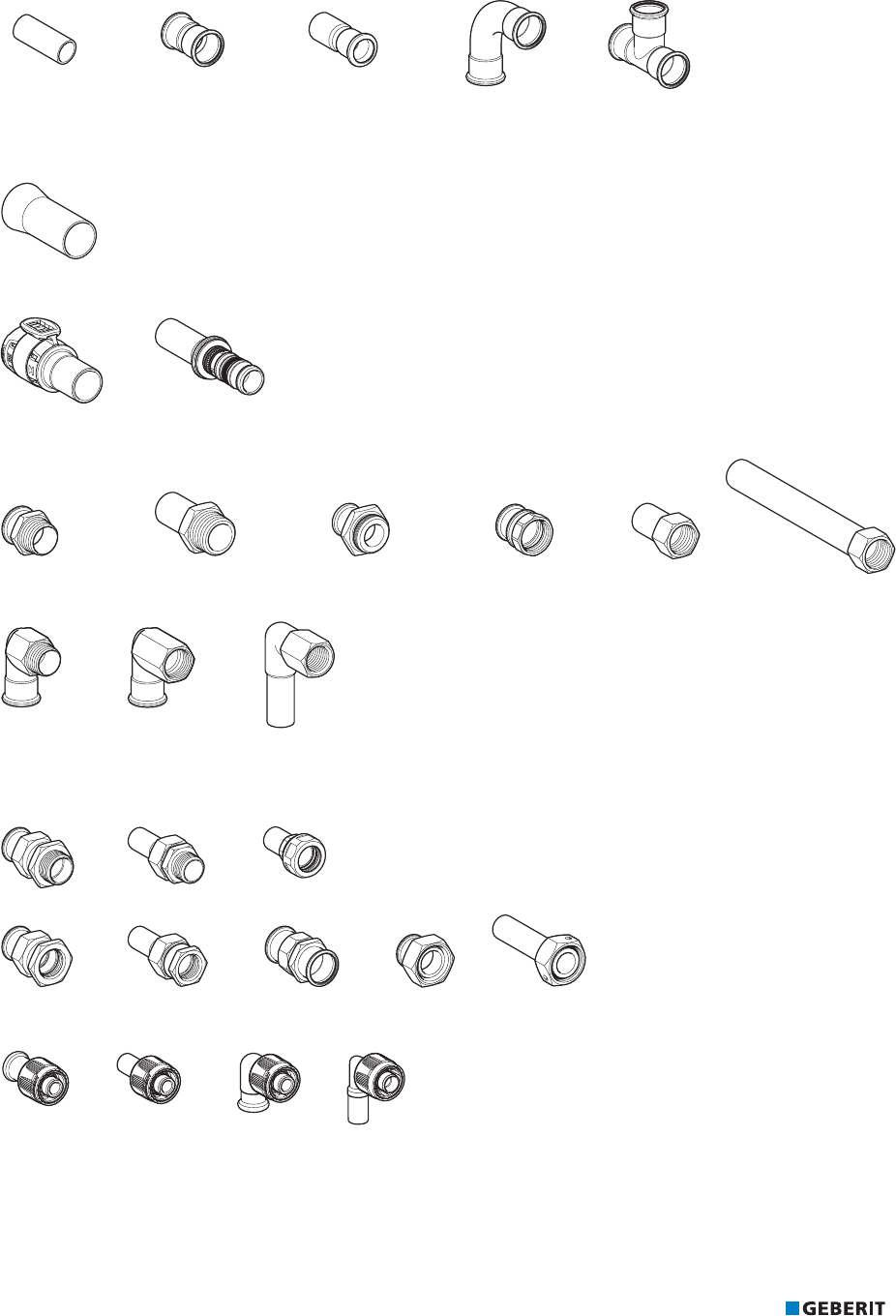
Fittings
Standard fittings
Figure6: Geberit Mapress Stainless Steel pressfittings
Adapters, permanent
Figure7: Geberit Mapress Stainless Steel adapter with weld-on and plain end
Figure8: Connections from Geberit FlowFit, Geberit Mepla to Geberit Mapress
Figure9: Geberit Mapress Stainless Steel adapters with male thread and adapters with female thread
Figure10: Geberit Mapress Stainless Steel elbow adapter 90°
Adapters and connections, removable
Figure11: Geberit Mapress Stainless Steel adapters and adapter unions
Figure12: Geberit Mapress adapters with MasterFix

PRINCIPLES GEBERIT MAPRESS STAINLESS STEEL
24
Figure13: Geberit Mapress Stainless Steel components for flange connections
Catches
Figure14: Geberit Mapress Stainless Steel cap
Axial expansion fitting, feed-through
Figure15: Geberit Mapress Stainless Steel axial expansion fitting and ceiling feed-through
Connections
Figure16: Geberit connections made of stainless steel and gunmetal

PRINCIPLES GEBERIT MAPRESS STAINLESS STEEL
25
Accessories
The following accessories are available for Geberit Mapress Stainless Steel:
Figure17: Geberit insulation for connections
Figure18: Geberit contact protection, as a hose or adhesive tape, yellow
Figure19: Geberit sealing tape
CIIR, black
HNBR, yellow
FKM, blue
FKM, white
Figure20: Geberit Mapress seal rings
EPDM, black FPM, green Centellen 3822 Centellen 3825 Centellen 3822
Figure21: Geberit Mapress flat gaskets and flange gasket
Figure22: Geberit pipe fastenings
Figure23: Geberit fastenings for connections

PRINCIPLES GEBERIT MAPRESS STAINLESS STEEL
26
Pipe valve fittings
Figure24: Geberit Mapress stop valves
Figure25: Geberit Mapress concealed stop valves
Figure26: Geberit Mapress ball valves
Figure27: Geberit Mapress concealed ball valves
Figure28: Geberit Mapress Stainless Steel non-return valve, flanged
Further information on the different designs and applications as well as on various accessories such as actuator levers, handles and
spindle extensions can be found in the online or printed catalogue.
Tools
The following processing tools are available for Geberit Mapress:
• Geberit Mapress pressing attachments
– pressing jaws
– pressing collars and adapter jaws
• Geberit Mapress pipe cutter
• Geberit pipe deburrer
• Geberit stripping tool
• Geberit Mapress insertion distance template with marker pen
• Geberit pressing tools

PRINCIPLES GEBERIT MAPRESS STAINLESS STEEL
27
1.2.3 Pipe marking
Marking of Geberit Mapress Stainless Steel system pipe CrNiMo
The marking of Geberit Mapress Stainless Steel system pipes 1.4401 includes the information in the table in the specified order. A pipe
with a dimension of d28 mm is used as an example.
Geberit company logo
Geberit Mapress Product name
191025-II Manufacturing date (25.10.2019, afternoon shift)
x Manufacturer's mark as agreed
325420 Melt number according to 3.1 Acceptance test certificate
28x1.2 Outer pipe diameter and wall thickness [mm]
1.4401/316 Material number EN/AISI
MPA NRW Inspection authority
DVGW DW xxxXATxxxx Drinking water approval marks for Germany
67-1802 ATEC xx/xx-xxxx Approval marks for France
KIWA Kxxxx Approval marks for the Netherlands
ATG xxxx Approval marks for Belgium
SITAC xxxx xxxx/xx Approval marks for Sweden
ÖVGW W xxxx Approval marks for Austria
WM-xxxxx ATS xxxx.xxx
Approval marks for Australia
DVGW DG xxxxBLxxxx GAS Gas approval marks for Germany
TÜV.A. xxx-xx VdTÜV component marking for Germany
FM mark (USA approval, d22–108)
VdS G xxxxxxx Sprinkler approval marks for Germany
LPCB Approval marks for the United Kingdom
CE marking
x Variable content
Marking of Geberit Mapress Stainless Steel system pipe CrMoTi
The marking of Geberit Mapress Stainless Steel system pipes 1.4521 includes the information in the table in the specified order. A pipe
with a dimension of d28 mm is used as an example:
Company logo
Geberit Mapress Product name
191025-II Manufacturing date and shift (25.10.2019, afternoon shift)
x Manufacturer's mark as agreed
325420 Melt number according to 3.1 Acceptance test certificate
28x1.2 Outer pipe diameter and wall thickness [mm]
1.4521/444 Material number EN/AISI
MPA NRW Inspection authority
DVGW DW xxxxATxxxx Approval marks for Germany
ATG xxxx Approval marks for Belgium
ÖVGW W xxxx Approval marks for Austria
SVGW xxxx-xxxx Approval marks for Switzerland
CE marking
x Variable content

PRINCIPLES GEBERIT MAPRESS STAINLESS STEEL
28
Marking of Geberit Mapress Stainless Steel system pipe CrNi
The marking of Geberit Mapress Stainless Steel system pipes 1.4301 includes the information in the table in the specified order. A pipe
with a dimension of d28 mm is used as an example.
Company logo
Geberit Mapress Product name
191025-I Manufacturing date and shift (25.10.2019, early shift)
Zxx Manufacturer's mark as agreed
325420 Melt number according to 3.1 Acceptance test certificate
28x1.2 Outer pipe diameter and wall thickness [mm]
1.4301/304 Material number EN/AISI
CE marking
ATG xxxx Approval marks for Belgium
x Variable content

PRINCIPLES GEBERIT MAPRESS STAINLESS STEEL
29
1.2.4 Application examples for fittings
Geberit Mapress Stainless Steel adapters, permanent
Figure29: Weld-on adapter
1 Geberit Mapress Stainless Steel adapter with weld-on and plain end
2 Steel pipe, non-alloy
3 Geberit Mapress Stainless Steel pressfitting
Figure30: Geberit FlowFit adapter to Geberit Mapress, with plain end
1 Geberit FlowFit adapter to Geberit Mapress, with plain end
2 Geberit Mapress system pipe
3 Geberit system pipe ML
Figure31: Connection to Geberit Mepla
1 Geberit Mepla adapter to Geberit Mapress, with plain end
2 Geberit Mepla system pipe
3 Geberit Mapress Stainless Steel pressfitting
Figure32: Connection to female thread
1 Geberit Mapress Stainless Steel adapter with male thread
2 Threaded socket with female thread
3 Geberit Mapress Stainless Steel system pipe

PRINCIPLES GEBERIT MAPRESS STAINLESS STEEL
30
Figure33: Connection to stop valve
1 Geberit Mapress Stainless Steel adapter with male thread and plain end
2 Geberit Mapress Stainless Steel T-piece
3 Angle-seat valve
Figure34: Connection to male thread
1 Geberit Mapress Stainless Steel adapter with female thread
2 Steel pipe with male thread
3 Geberit Mapress Stainless Steel system pipe
Figure35: Connection to outside tap
1 Geberit Mapress Stainless Steel adapter with female thread and plain end
2 Outside tap with male thread
3 Geberit Mapress Stainless Steel T-piece

PRINCIPLES GEBERIT MAPRESS STAINLESS STEEL
31
Geberit Mapress Stainless Steel adapters and connections, removable
Figure36: Tool-free connection with MasterFix
1 Geberit Mapress adapter with MasterFix
2 Geberit Mapress Stainless Steel system pipe
3 Geberit fitting with male thread MF 1/2" (elbow tap connector 90°)
4 Geberit Mapress adapter with MasterFix and plain end
5 Geberit Mapress Stainless Steel pressfitting (T-piece)
Figure37: Tap connector, straight, with MasterFix
1 Geberit tap connector, straight, with male thread MF 1/2"
2 Mounting plate, sound insulation set
3 Geberit Mapress adapter with MasterFix
4 Geberit Mapress adapter with MasterFix and plain end
Figure38: Tap connector, straight, with MasterFix, drywall construction
1 Geberit tap connector set, straight, with male thread MF 1/2", premounted, drywall construction
2 Geberit Mapress adapter with MasterFix
3 Geberit Mapress adapter with MasterFix and plain end

PRINCIPLES GEBERIT MAPRESS STAINLESS STEEL
32
Figure39: Connection to male thread
1 Geberit Mapress Stainless Steel adapter with union nut
2 Pipe valve fitting with male thread G
3 Geberit Mapress Stainless Steel system pipe
Figure40: Connection to corrugated pipes
1 Geberit Mapress adapter union with clamping ring for corrugated pipes, non-potable water, plain end
2 Corrugated pipe
3 Geberit Mapress Stainless Steel pressfitting (threaded socket)
Figure41: Connection to flange valves
1 Geberit Mapress Stainless Steel flange with plain end. Accessories: Geberit flange gasket and screws for flange connection
2 Geberit Mapress Stainless Steel flange with pressing socket. Accessories: Geberit flange gasket and screws for flange
connection
3 Geberit Mapress Stainless Steel system pipe
4 Flange valve
5 Geberit Mapress Stainless Steel pressfitting (T-piece)
Figure42: Connection to Geberit Mapress Stainless Steel with flanges
1 Geberit Mapress Stainless Steel flanged stub with plain end for loose flange Accessories: Geberit flange gasket, screws for
flange connection
2 Loose flange according to EN 1092-1, flange type 02
3 Flange valve

PRINCIPLES GEBERIT MAPRESS STAINLESS STEEL
33
Geberit Mapress Stainless Steel adapters and connections (gas)
Figure43: Adapter to cutting ring connection
1 Geberit Mapress Stainless Steel adapter to cutting ring connection (gas)
2 Cutting ring connection
3 Geberit Mapress Stainless Steel system pipe
Figure44: Connection to gas valves, conical-sealing
1 Geberit Mapress Stainless Steel adapter with union nut made of CrNi steel (gas)
2 Gas meter
3 Geberit Mapress Stainless Steel system pipe
Figure45: Connection for two-pipe gas meter
1 Geberit Mapress Stainless Steel elbow tap connector90°, offset, circular hole 50mm (gas)
2 Mounting bracket for gas meter
3 Geberit Mapress Stainless Steel system pipe

PRINCIPLES GEBERIT MAPRESS STAINLESS STEEL
34
1.2.5 System characteristics
The following table gives an overview of the most important system characteristics of Geberit Mapress Stainless Steel:
Characteristic Meaning
Diffusion barrier Geberit Mapress Stainless Steel fittings, pipes and pressed joints form a barrier
against diffusion.
Hot water resistance Permanent 0‒100°C, saturated steam up to a maximum of 120°C
Resistance to cold Down to -30°C under the condition that the medium in the pipe does not freeze
Material abrasion If the recommended flow rate is observed, no material abrasion occurs in the pipe.
UV resistance UV-resistant and therefore also suitable for outdoor use.
Corrosion resistance Geberit Mapress Stainless Steel is largely resistant to corrosion in normal, dry
environments as well as to a wide range of liquid and gaseous media. Corrosion
protection is required in aggressive environments.
Electrical conductivity Electrically conductive, must be integrated into the main equipotential bonding.
Transmission of structure-borne
sound
In the case of decoupling from the building structure, there is no transmission of
structure-borne sound.
Fire behaviour Geberit metal pipes are non-combustible.
1.2.6 Certificates for Geberit Mapress Stainless Steel
The Geberit Mapress Stainless Steel systems have certificates from the following bodies, amongst others.
Certification body Application
DVGW Drinking water installations, gas installations
ÖVGW
SVGW
BSI
CSTB Drinking water installations
KIWA-NL
WRAS
VdS Sprinkler systems
FM approvals
BRE LPCB
TÜV TÜV component certificate with a supplementary expert report for industrial applications
DIBt Industrial applications
ABS Shipbuilding
BV
CCS
RINA
RMRS

PRINCIPLES GEBERIT MAPRESS STAINLESS STEEL
35
1.2.7 Technical data
Geberit Mapress Stainless Steel system pipe CrNiMo
Product material and product material characteristics
Table4: Material
Material designation Austenitic stainless steel CrNiMo (chromium-nickel-molybdenum)
Short name according to EN 10088 X5CrNiMo17-12-2
Material number EN 1.4401
Material number AISI 316
Table5: Physical characteristics
Thermal expansion coefficient α at 20–100°C 0,0165 mm/(m·K)
Thermal conductivity λ at 20°C 15 W/(m·K)
Specific thermal capacity c at 20 °C 500 J/(kg·K)
Surface roughness k 1,5 µm
Building material class EN 13501 A1
DIN 4102 Part1 A1
Table6: Mechanical characteristics
Heat treatment Annealed (all pipe dimensions)
Tensile strength R
m
510–710N/mm
2
0.2% expansion limit R
p0.2
≥220N/mm
2
Elongation at break A
5
>40%
Pipe data
G
GL
V
Table7: Geberit Mapress Stainless Steel system pipe 1.4401
DN d
[mm]
s
[mm]
di
[mm]
m
R
[kg/m]
m
RW
[kg/m]
V
[l/m]
10 12 1 10 0.276 0.355 0.079
12 15 1 13 0.351 0.484 0.133
15 18 1 16 0.426 0.627 0.201
20 22 1.2 19.6 0.626 0.928 0.302
25 28 1.2 25.6 0.806 1.321 0.515
32 35 1.5 32 1.260 2.064 0.804
40 42 1.5 39 1.523 2.718 1.195
50 54 1.5 51 1.974 4.017 2.043
65 76.1 2 72.1 3.715 7.798 4.083
80 88.9 2 84.9 4.357 10.018 5.661
100 108 2 104 5.315 13.810 8.495
m
R
Pipe weight
m
RW
Pipe weight with water at 10°C
V Pipe volume

PRINCIPLES GEBERIT MAPRESS STAINLESS STEEL
36
Geberit Mapress Stainless Steel system pipe CrMoTi
Product material and product material characteristics
Table8: Material
Material designation Ferritic stainless steel CrMoTi (chromium-molybdenum-titanium)
Short name according to EN10088 X2CrMoTi 18-2
Material number EN 1.4521
Material number AISI 444
Table9: Physical characteristics
Thermal expansion coefficient α at 20–100°C 0,0104 mm/(m·K)
Thermal conductivity λ at 20°C 23 W/(m·K)
Specific thermal capacity c at 20 °C 430 J/(kg·K)
Surface roughness k 1,5 µm
Building material class EN13501 A1
DIN 4102 Part1 A1
Table10: Mechanical characteristics
Heat treatment Annealed (only d15–22mm)
Tensile strength R
m
≥ 400N/mm
2
0.2% expansion limit R
p0.2
≥ 280N/mm
2
Elongation at break A
5
>20%
Pipe data
G
GL
V
Table11: Geberit Mapress Stainless Steel system pipe 1.4521
DN d
[mm]
s
[mm]
di
[mm]
m
R
[kg/m]
m
RW
[kg/m]
V
[l/m]
10 12 1 10 0.266 0.345 0.079
12 15 1 13 0.339 0.472 0.133
15 18 1 16 0.411 0.612 0.201
20 22 1.2 19.6 0.604 0.906 0.302
25 28 1.2 25.6 0.778 1.293 0.515
32 35 1.5 32 1.216 2.202 0.804
40 42 1.5 39 1.470 2.665 1.195
50 54 1.5 51 1.905 3.948 2.043
m
R
Pipe weight
m
RW
Pipe weight with water at 10°C
V Pipe volume

PRINCIPLES GEBERIT MAPRESS STAINLESS STEEL
37
Geberit Mapress Stainless Steel system pipe CrNi
Product material and product material characteristics
Table12: Material
Material designation Austenitic stainless steel CrNi (chromium-nickel)
Abbreviation according to EN 10088 X5CrNi18-10
Material number EN 1.4301
Material number AISI 304
Table13: Physical characteristics
Thermal expansion coefficient α at 20–100°C 0,016 mm/(m·K)
Thermal conductivity λ at 20°C 15 W/(m·K)
Specific thermal capacity c at 20 °C 500 J/(kg·K)
Surface roughness k 1,5 µm
Building material class EN13501 A1
DIN 4102 Part1 A1
Table14: Mechanical characteristics
Heat treatment condition Annealed (only d15–22mm)
Tensile strength R
m
500–700N/mm
2
0.2% expansion limit R
p0.2
≥ 220N/mm
2
Elongation at break A
5
>40%
Pipe data
G
GL
V
Table15: Geberit Mapress Stainless Steel system pipe 1.4301
DN d
[mm]
s
[mm]
di
[mm]
m
R
[kg/m]
m
RW
[kg/m]
V
[l/m]
12 15 1 13 0.348 0.481 0.133
15 18 1 16 0.422 0.623 0.201
20 22 1.2 19.6 0.620 0.922 0.302
25 28 1.2 25.6 0.798 1.313 0.515
32 35 1.5 32 1.247 2.051 0.804
40 42 1.5 39 1.508 2.703 1.195
50 54 1.5 51 1.955 3.998 2.043
65 76.1 1.5 73.1 2.777 6.860 4.083
80 88.9 1.5 85.9 3.254 8.915 5.661
100 108 2 104 5.262 13.757 8.495
m
R
Pipe weight
m
RW
Pipe weight with water at 10°C
V Pipe volume

PRINCIPLES GEBERIT MAPRESS STAINLESS STEEL
38
Pressfittings
Product material and product material characteristics
Table16: Material of Geberit Mapress Stainless Steel pressfitting
Material designation Austenitic stainless steel CrNiMo (chromium-nickel-molybdenum)
Short name according to EN 10088 X5CrNiMo17-12-2
Material number EN 1.4401
Material number AISI 316
For information on the recycling code of the pressing indicator and protection plug, see the ‘Disposal’ chapter.
Table17: Physical properties of Geberit Mapress Stainless Steel pressfitting
Thermal expansion coefficient α at 20–100°C 0,0165 mm/(m·K)
Thermal conductivity λ at 20°C 15 W/(m·K)
Specific thermal capacity c at 20 °C 500 J/(kg·K)
Surface roughness k 1,5 µm
Building material class A1 according to EN13501
A1 according to DIN 4102 Part1
Table18: Mechanical characteristics of Geberit Mapress Stainless Steel pressfitting
Heat treatment Annealed (all pipe dimensions)
Tensile strength R
m
510–710N/mm
2
0.2% expansion limit R
p0.2
≥220N/mm
2
Elongation at break A
5
>40%

PRINCIPLES GEBERIT MAPRESS STAINLESS STEEL
39
System seals
Material and temperature resistance
Table19: Geberit Mapress seal rings for Geberit Mapress Stainless Steel
CIIR, black HNBR, yellow FKM, blue FKM, white
d
[mm]
15–108 15–108 15–108 15–108
Material
Chlorinated butyl
rubber
Hydrogenated
acrylonitrile-butadiene
rubber
Fluoro rubber Fluoro rubber
Operating temperature
1)
[°C]
-30–+120 -20–+70 -25–+140
2)
-25–+180
3)
5–155
Leaky if unpressed
Applies
Does not apply
1) Additional information on the operating temperatures, together with the uses and operating pressures, is given in the respective
usage overviews. The current usage overviews can be found in the online catalogue or in the printed catalogue.
2) Use only approved antifreeze agent according to the "Corrosion and antifreeze agent” technical information.
3) When used in thermal media (solar): Service life with collector downtime: 200h/a at 180°C, 60h/a at 200°C, total service life:
500h at 220°C.
Table20: Geberit Mapress flat gaskets for Geberit Mapress Stainless Steel
EPDM, black FPM, green Centellen®
HDWS3822
Centellen®
HDWS3825
G 1/2 to 23/8" 3/4 to 23/8" 3/4 to 23/8" 1/2 to 31/2"
Material
Ethylene propylene
diene monomer rubber
Fluoro rubber
Aramid fibres with
inorganic reinforcing
materials and rubber as
a binding material
Aramid fibres with
inorganic reinforcing
materials and rubber as
a binding material
Operating temperature
1)
[°C]
0–100 -30–+180 -20–+155 -30–+150
1) Additional information on the operating temperatures, together with the uses and operating pressures, is given in the respective
usage overviews. The current usage overviews can be found in the online catalogue or in the printed catalogue.
Table21: Geberit Mapress flange gasket and O-rings for Geberit Mapress Stainless Steel
Geberit Mapress flange gasket
Centellen® HD WS 3822
O-rings for Geberit Mapress screw
connections, conical-sealing, gas
Nominal width
DN
15–100
G
7/8, 11/8 and 13/8"
Material Aramid fibres with inorganic reinforcing materials
and rubber as a binding material
Hydrogenated acrylonitrile-butadiene rubber
Operating temperature
[°C]
-30–+180 -20–+70
Does not apply
PRINCIPLES GEBERIT MAPRESS STAINLESS STEEL
40
The operating conditions specified in the relevant approvals, standards and technical regulations must be observed for each
application. These may differ from the information in the usage overviews.
Maximum axial load of pressed joint
The following maximum axial loads apply for Geberit Mapress Stainless Steel pressed joints with stainless steel 1.4401 in applications.
Pressing attachment d
[mm]
Maximum axial load
[kN]
Pressing jaw with
compatibility [2]/[3]
15 1.4
18 2.0
22 1.9
28 1.9
35 1.9
Pressing collar with
compatibility [2]/[3]/[2XL]
35 3.6
42 5.2
54 8.6
76.1 10.6
88.9 12.2
108 19.5

PRINCIPLES GEBERIT MAPRESS CARBON STEEL
41
1.3 GEBERIT MAPRESS CARBON STEEL
1.3.1 Overview of Geberit Mapress Carbon Steel systems
Geberit Mapress Carbon Steel is a supply system with pipes made of zinc-plated non-alloy steel, in which pipes and fittings are pressed
to form permanent, technically tight pipes.
Geberit Mapress Carbon Steel is suitable for applications in closed systems (e.g. heating or cooling systems).
The most common uses are listed below for each Geberit Mapress Carbon Steel system. Other applications (media), together with the
operating temperatures and operating pressures, are listed in the respective usage overviews.
The current usage overviews can be found in the online catalogue or in the printed catalogue.
The operating conditions specified in the relevant approvals, standards and technical regulations must be observed for each
application. These may differ from the information in the usage overviews.
Geberit Mapress Carbon Steel
Seal ring Fitting System pipe Combined pipe and fitting
dimensions
Most common uses
CIIR, black
Carbon steel
1.0034
Carbon steel 1.0034,
outside zinc-plated
d12‒108mm
• Heating water
• Cooling water with and without antifreeze
agent
• Remote network heating water ≤120°C
CIIR, black
Carbon steel
1.0034
Carbon steel 1.0034,
plastic-jacketed
d12‒54mm
• Heating water
• Cooling water with and without antifreeze
agent
CIIR, black
Carbon steel
1.0034
Carbon steel 1.0215,
inside and outside zinc-
plated
d15‒108mm
• Compressed air (oil class3)

PRINCIPLES GEBERIT MAPRESS CARBON STEEL
42
Geberit Mapress Carbon Steel, FKM, blue
Seal ring Fitting System pipe Combined pipe and fitting
dimensions
Most common uses
FKM, blue
Carbon steel
1.0034
Carbon steel 1.0034,
outside zinc-plated
d12‒108mm
• Remote network heating water ≤140°C
• Thermal medium (solar)
• Mineral and lubricating oils
• Motor fuels (e.g. diesel)
FKM, blue
Carbon steel
1.0034
Carbon steel 1.0215,
inside and outside zinc-
plated
d15‒108mm
• Compressed air (oil class 3‒X)

PRINCIPLES GEBERIT MAPRESS CARBON STEEL
43
1.3.2 System components
The Geberit Mapress Carbon Steel system consists of the following components:
• system pipes
• fittings with system seals
• pipe valve fittings
• accessories
• tools
System pipes
Geberit Mapress Carbon Steel system pipe, outside zinc-plated
Outer diameter 12–108 mm
Description • Welded, thin-walled precision steel pipe made of non-alloy steel 1.0034 E 195 (EN
10305)
• With red lettering
Properties • Outside zinc-plated with an 8μm thick protective coating (FeZn8B, chromatised)
• Bendable from d12–108mm
1)
1) Can be bent by hand up to a pipe diameter of d28mm. Special pipe bending machines are required for bending from a diameter of
d35mm.
Geberit Mapress Carbon Steel system pipe, plastic-jacketed
Outer diameter 12–54 mm
Description • Welded, thin-walled precision steel pipe made of non-alloy steel 1.0034/E 220 (EN
10305), with plastic jacketing made of polypropylene (PP), cream white (RAL
9001)
Properties • Outside zinc-plated with an 8μm thick protective coating (FeZn8B, chromatised)
• Plastic jacket can only be used down to -10°C
• Limited bending by hand up to and including d18mm
Geberit Mapress system pipes (plastic-jacketed) should not be bent as this can damage the jacketing (over-expansion,
delamination).
Geberit Mapress Carbon Steel system pipe, inside and outside zinc-plated
Outer diameter 15-108 mm
Description • Welded, thin-walled precision steel pipe made of non-alloy steel 1.0215 E 220 (EN
10305)
• With black lettering
Properties • Sendzimir galvanised on the inside and outside with a 20μm thick zinc coating.
With a VDS certificate for compressed air systems
• Bendable from d15–108mm
1)
1) Can be bent by hand up to a pipe diameter of d28mm. Special pipe bending machines are required for bending from a diameter of
d35mm.

PRINCIPLES GEBERIT MAPRESS CARBON STEEL
44
Pressfittings
Geberit Mapress Carbon Steel pressfitting with seal ring CIIR, black
Outer diameter 12–108 mm
Description • Pressfitting made of non-alloy steel 1.0034 E195 (EN 10305), for pressing the
Mapress Carbon Steel system pipes for standard applications, e.g. heating
installations
• Translucent protection plug
• Red pressing indicator
• Seal ring CIIR, black
Properties • Outside zinc-plated with an 8μm thick protective coating (FeZn8B, chromatised)
• Leaky if unpressed
Geberit Mapress Carbon Steel pressfittings with seal ring FKM, blue
Outer diameter 15–108 mm
Description • Pressfitting made of non-alloy steel 1.0034 (EN 10305), outside zinc-plated, for
industrial and solar applications
• Anthracite protection plug
• Red pressing indicator
• Seal ring FKM, blue
Properties • Outside zinc-plated with an 8μm thick protective coating (FeZn8B, chromatised)

PRINCIPLES GEBERIT MAPRESS CARBON STEEL
45
Fittings
Standard fittings
Figure46: Geberit Mapress Carbon Steel standard fittings
Adapters, permanent
Figure47: Geberit Mapress Carbon Steel adapter with weld-on and plain end
Figure48: Connections from Geberit FlowFit, Geberit Mepla to Geberit Mapress
Figure49: Geberit Mapress Carbon Steel adapters with male thread and adapters with female thread
Figure50: Geberit Mapress Carbon Steel elbow adapters 90° and bend adapters 90°

PRINCIPLES GEBERIT MAPRESS CARBON STEEL
46
Adapters and connections, removable
Figure51: Geberit Mapress Carbon Steel adapters and adapter unions
Figure52: Flange connections
Catches
Figure53: Geberit Mapress Carbon Steel cap
Axial expansion fitting
Figure54: Geberit Mapress Carbon Steel axial expansion fitting
Connections for heating
Figure55: Geberit connections made of carbon steel and gunmetal

PRINCIPLES GEBERIT MAPRESS CARBON STEEL
47
Figure56: Geberit connector boxes
Figure57: Geberit Mapress Carbon Steel venturi nozzle for single-pipe heating
Accessories
The following accessories are available for Geberit Mapress Carbon Steel:
Figure58: Geberit insulation hose
Figure59: Geberit sealing tape
Figure60: Covers for pipes
CIIR, black FKM, blue
Figure61: Geberit Mapress seal rings
EPDM, black FPM, green Centellen 3822 Centellen 3825 Centellen 3822
Figure62: Geberit Mapress flat gaskets and flange gasket

PRINCIPLES GEBERIT MAPRESS CARBON STEEL
48
Figure63: Geberit pipe fastenings
Pipe valve fittings
The following pipe valve fittings are available for Geberit Mapress Carbon Steel:
Figure64: Geberit Mapress ball valve, non-potable water
Further information on the different designs and applications as well as on various accessories such as actuator levers, handles and
spindle extensions can be found in the online or printed catalogue.
Tools
The following processing tools are available for Geberit Mapress:
• Geberit Mapress pressing attachments
– pressing jaws
– pressing collars and adapter jaws
• Geberit Mapress pipe cutter
• Geberit pipe deburrer
• Geberit stripping tool
• Geberit Mapress insertion distance template with marker pen
• Geberit pressing tools

PRINCIPLES GEBERIT MAPRESS CARBON STEEL
49
1.3.3 Pipe marking
Marking of Geberit Mapress Carbon Steel system pipe 1.0034
The marking of Geberit Mapress Carbon Steel system pipes 1.0034 includes the information in the table in the specified order. A pipe
with a dimension of d28 mm is used as an example.
Company logo
Geberit Mapress Product name
130222-II Manufacturing date and shift (22.02.2013, afternoon shift)
Zxx Manufacturer's mark as agreed
28x1.5 Pipe dimension [mm] (pipe diameter x wall thickness)
1.0034/1009 Material number EN/AISI
67-1802 ATEC xx/xx-xxxx Approval marks for France
ATG xxxx Approval marks for Belgium
NPW Non-potable water (non-potable water)
Marking of Geberit Mapress Carbon Steel system pipe 1.0215
The marking of Geberit Mapress Carbon Steel system pipes 1.0215 includes the information in the table in the specified order. A pipe
with a dimension of d54 mm is used as an example.
Company logo
Geberit Mapress Product name
080201-II Manufacturing date and shift (01.02.2008, afternoon shift)
Zxx Manufacturer's mark as agreed
54x1.5 Outer pipe diameter and wall thickness [mm]
1.0215/1009 Material number EN/AISI
VdS G 4030020 Sprinkler approval mark for Germany d22–54
VdS G 4070025 Sprinkler approval mark for Germany d76,1–108

PRINCIPLES GEBERIT MAPRESS CARBON STEEL
50
1.3.4 Application examples for fittings
Geberit Mapress Carbon Steel adapters, permanent
Figure65: Weld-on adapter
1 Geberit Mapress Carbon Steel adapter with weld-on and plain end
2 Steel pipe, non-alloy
3 Geberit Mapress Carbon Steel pressfitting
Figure66: Connection to Geberit FlowFit
1 Geberit FlowFit adapter to Geberit Mapress, with plain end
2 Geberit Mapress Carbon Steel pressfitting
3 Geberit system pipe ML
Figure67: Connection to Geberit Mepla
1 Geberit Mepla adapter to Geberit Mapress, with plain end
2 Geberit Mepla system pipe
3 Geberit Mapress pressfitting
Figure68: Connection to female thread
1 Geberit Mapress Carbon Steel adapter with male thread
2 Threaded socket with female thread
3 Geberit Mapress Carbon Steel system pipe

PRINCIPLES GEBERIT MAPRESS CARBON STEEL
51
Figure69: Connection to stop valve
1 Geberit Mapress Carbon Steel adapter with male thread and plain end
2 Geberit Mapress Carbon Steel pressfitting (T-piece)
3 Slide valves
Figure70: Connection to male thread
1 Geberit Mapress Carbon Steel adapter with female thread
2 Steel pipe with male thread
3 Geberit Mapress Carbon Steel system pipe
Figure71: Connection to male thread
1 Geberit Mapress Carbon Steel adapter with union nut
2 Pipe valve fitting with male thread G (heating fill valve)
3 Geberit Mapress Carbon Steel T-piece

PRINCIPLES GEBERIT MAPRESS CARBON STEEL
52
Geberit Mapress Carbon Steel adapters and connections, removable
Figure72: Connection to male thread
1 Geberit Mapress Carbon Steel system pipe
2 Geberit Mapress Carbon Steel adapter with union nut
3 Circulation pump with male thread G
Figure73: Connection to corrugated pipes
1 Geberit Mapress adapter union with clamping ring for corrugated pipes, non-potable water, plain end
2 Corrugated pipe
3 Geberit Mapress Carbon Steel pressfitting (threaded socket)
Figure74: Connection to flange valves
1 Geberit Mapress Carbon Steel flange with plain end. Accessories: Flange gasket and screws for Geberit flange connection
2 Geberit Mapress Carbon Steel flange with pressing socket. Accessories: Flange gasket and screws for Geberit flange
connection
3 Geberit Mapress Carbon Steel system pipe
4 Flange valve
5 Geberit Mapress Carbon Steel pressfitting (T-piece)

PRINCIPLES GEBERIT MAPRESS CARBON STEEL
53
Geberit Mapress Carbon Steel heating connections
Figure75: Radiator connection for pipe laying with a distance to the wall
1 Geberit Mapress metal pipe connector bend 90° with insulation box and union connector for Euro cone
2 Geberit Mapress Carbon Steel pipe nipple, outside zinc-plated
3 Geberit Mapress T-piece crossing with insulation box
4 Geberit Mapress Carbon Steel system pipe (inlet / return flow)
Figure76: Radiator connection for pipe laying near the wall
1 Geberit Mapress metal pipe connection T-piece with insulation box and union connector for Euro cone
2 Geberit Mapress Carbon Steel system pipe (inlet / return flow)

PRINCIPLES GEBERIT MAPRESS CARBON STEEL
54
Figure77: Connection to end piece for riser pipe
1 Geberit Mapress Carbon Steel system pipe (inlet / return flow)
2 Geberit Mapress Carbon Steel connector end piece for inlet and return flow, long
Figure78: Connection to riser pipe, 1 radiators
1 Geberit Mapress Carbon Steel system pipe (inlet / return flow)
2 Geberit Mapress Carbon Steel connector T-piece for inlet and return flow, long
Figure79: Connection to riser pipe, 2 radiators
1 Geberit Mapress Carbon Steel system pipe (inlet / return flow)
2 Geberit Mapress Carbon Steel connector pipe cross for inlet and return flow, long

PRINCIPLES GEBERIT MAPRESS CARBON STEEL
55
Figure80: Connection for surface-mounted pipe (skirting board), with a distance between the inlet and return flow
1 Geberit Mapress Carbon Steel T-piece, reduced
2 Geberit Mapress Carbon Steel system pipe (inlet / return flow)
3 Geberit Mapress Carbon Steel connector T-piece set for return flow
Figure81: Connection for surface-mounted pipe (skirting board), with connector 4cm
1 Geberit Mapress Carbon Steel connector T-piece for inlet and return flow
2 Geberit Mapress Carbon Steel system pipe (inlet / return flow)
Figure82: Connection for surface-mounted pipe (skirting board), with extendible connector
1 Geberit Mapress Carbon Steel connector T-piece set for inlet and return flow
2 Geberit Mapress Carbon Steel system pipe (inlet / return flow)

PRINCIPLES GEBERIT MAPRESS CARBON STEEL
56
Figure83: Skirting board connection with adapter with union connector for Euro cone
1 Geberit Mapress Carbon Steel connector T-piece set for inlet and return flow, with union connector for Euro cone
2 Geberit Mapress Carbon Steel system pipe (inlet / return flow)
Figure84: Union connector for Euro cone
1 Union connector for Euro cone
2 Geberit Mapress system pipe
3 Valve tap block with Euro cone
Figure85: Connector with union nut
1 Geberit Mapress Carbon Steel connector with union nut
2 Valve tap block with male thread
3 Geberit Mapress Carbon Steel system pipe

PRINCIPLES GEBERIT MAPRESS CARBON STEEL
57
Figure86: Radiator connector box type C for higher screed constructions
1 Geberit Mapress connector box type C
2 Geberit Mapress T-piece crossing with insulation box

PRINCIPLES GEBERIT MAPRESS CARBON STEEL
58
1.3.5 System characteristics
The following table gives an overview of the most important system characteristics of Geberit Mapress Carbon Steel:
Characteristic Meaning
Diffusion barrier Geberit Mapress Carbon Steel fittings, pipes and pressed joints form a barrier
against diffusion.
Hot water resistance Permanent 0‒100°C, remote network heating water ≤120°C
Resistance to cold Down to -30°C under the condition that the medium in the pipe does not freeze
Material abrasion If the recommended flow rate is observed, no material abrasion occurs in the pipe.
UV resistance UV-resistant
Corrosion resistance Corrosion-resistant in closed systems, in which the oxygenation capacity is
excluded, as well as against a variety of liquids and gaseous media. Corrosion
protection is required in damp or aggressive environments.
Electrical conductivity Electrically conductive, must be integrated into the main equipotential bonding.
Transmission of structure-borne
sound
In the case of decoupling from the building structure, there is no transmission of
structure-borne sound.
Fire behaviour Geberit metal pipes are non-combustible.
1.3.6 Geberit Mapress Carbon Steel certificates
The Geberit Mapress Carbon Steel systems have certificates from the following bodies, amongst others.
Certification body Application
TÜV TÜV component certificate with a supplementary expert report for industrial applications
DiBt Industrial applications
CSTB Heating systems
VdS Sprinkler systems
FM approvals
BRE LPCB
ABS Shipbuilding
BV
CCS
DNV

PRINCIPLES GEBERIT MAPRESS CARBON STEEL
59
1.3.7 Technical data
Geberit Mapress Carbon Steel system pipe, outside zinc-plated
Product material and product material characteristics
Table22: Material
Material designation Non-alloy steel
Short designation according to EN 10305 E195
Material number EN 1.0034
Material number AISI 1009
Type of galvanisation Galvanically zinc-plated, blue passivated
Layer design (EN10346:2015-10) FeZn8
Layer thickness 8µm
Table23: Physical characteristics
Thermal expansion coefficient α at 20–100°C 0,012 mm/(m·K)
Thermal conductivity λ at 20°C 60 W/(m·K)
Specific thermal capacity c at 20 °C 500 J/(kg·K)
Surface roughness k 10 µm
Building material class EN13501 A1
DIN 4102 Part1 A1
Table24: Mechanical characteristics
Tensile strength R
m
at d≤22mm 290–420N/mm
2
Tensile strength R
m
at d≥28mm 310–440N/mm
2
0.2 % expansion limit R
p0.2
at d≤22mm >260N/mm
2
0.2 % expansion limit R
p0.2
at d≤28mm >260–360N/mm
2
Elongation at break A
5
>25%

PRINCIPLES GEBERIT MAPRESS CARBON STEEL
60
Pipe data
G
GL
V
Table25: Geberit Mapress Carbon Steel system pipe 1.0034 outside zinc-plated
DN d
[mm]
s
[mm]
di
[mm]
m
R
[kg/m]
m
RW
[kg/m]
V
[l/m]
10 12 1.2 9.6 0.320 0.392 0.072
12 15 1.2 12.6 0.408 0.533 0.125
15 18 1.2 15.6 0.497 0.688 0.191
20 22 1.5 19 0.758 1.042 0.284
25 28 1.5 25 0.980 1.471 0.491
32 35 1.5 32 1.239 2.043 0.804
40 42 1.5 39 1.498 2.693 1.195
50 54 1.5 51 1.942 3.985 2.043
65 66.7 1.5 63.7 2.412 5.599 3.187
65 76.1 2 72.1 3.655 7.738 4.083
80 88.9 2 84.9 4.286 9.947 5.661
100 108 2 104 5.228 13.723 8.495
m
R
Pipe weight
m
RW
Pipe weight with water at 10°C
V Pipe volume

PRINCIPLES GEBERIT MAPRESS CARBON STEEL
61
Geberit Mapress Carbon Steel system pipe, plastic-jacketed
Product material and product material characteristics
Table26: Product material of Geberit Mapress Carbon Steel system pipe, plastic-jacketed
Material designation Non-alloy steel
Short designation according to EN 10305 E195
Material number EN 1.0034
Material number AISI 1009
Type of galvanisation Galvanically zinc-plated, blue passivated
Layer design according to EN10346:2015-10 FeZn8
Layer thickness 8µm
Material designation of pipe jacketing PP
Table27: Physical properties of Geberit Mapress Carbon Steel system pipe
Thermal expansion coefficient α at 20–100°C 0.012mm/(m·K)
Thermal conductivity λ of system pipe at 20°C 60 W/(m·K)
Specific thermal capacity c at 20 °C 500 J/(kg·K)
Surface roughness k 10 µm
Building material class of carbon steel pipe with
jacketing
EN13501–1 E
DIN 4102 Part1 B2, non-combustible,
dripping
Table28: Physical properties of Geberit Mapress Carbon Steel jacketing
Density ρ 0.95 g/cm
3
(non-porous, waterproof)
Thermal conductivity λ of jacketing at 20°C 0.22 W/(m·K)
Maximum operating temperature 120 °C
Minimum ambient temperature -10 °C
UV resistance Not UV-resistant
Building material class E according to EN13501
B2 according to DIN 4102 Part1
Table29: Mechanical characteristics of Geberit Mapress Carbon Steel system pipe, plastic-jacketed
Tensile strength R
m
at d≤22mm 290–420N/mm
2
Tensile strength R
m
at d≥28mm 310–440N/mm
2
0.2 % expansion limit R
p0.2
at d≤22mm >260N/mm
2
0.2 % expansion limit R
p0.2
at d≤28mm >260–360N/mm
2
Elongation at break A
5
>25%

PRINCIPLES GEBERIT MAPRESS CARBON STEEL
62
Table30: Required bending moment of Geberit Mapress Carbon Steel system pipe, plastic-jacketed
d
[mm]
s
[mm]
F
[Nm]
12 1.2 80
15 1.2 100
18 1.2 160
Geberit Mapress Carbon Steel system pipes with plastic jacketing can be processed down to -10°C.
Geberit Mapress system pipes (plastic-jacketed) should not be bent as this can damage the jacketing (over-expansion,
delamination).
Pipe data
G
'
GL
V
V
Table31: Geberit Mapress Carbon Steel system pipe 1.0034, plastic-jacketed
DN d
[mm]
D
[cm]
s
[mm]
s1
[mm]
di
[mm]
m
R
[kg/m]
m
RW
[kg/m]
V
[l/m]
10 12 1.4 1.2 0.9 9.6 0.338 0.410 0.072
12 15 1.7 1.2 0.9 12.6 0.434 0.559 0.125
15 18 2 1.2 0.9 15.6 0.536 0.727 0.191
20 22 2.4 1.5 0.9 19 0.824 1.108 0.284
25 28 3 1.5 0.9 25 1.052 1.543 0.491
32 35 3.7 1.5 0.9 32 1.320 2.124 0.804
40 42 4.4 1.5 0.9 39 1.620 2.815 1.195
50 54 5.6 1.5 0.9 51 2.098 4.141 2.043
m
R
Pipe weight
m
RW
Pipe weight with water at 10°C
V Pipe volume

PRINCIPLES GEBERIT MAPRESS CARBON STEEL
63
Geberit Mapress Carbon Steel system pipe, inside and outside zinc-plated
Product material and product material characteristics
Table32: Product material of Geberit Mapress Carbon Steel system pipe, inside and outside zinc-plated
Material designation Non-alloy steel
Short designation according to EN 10305 E220
Material number EN 1.0215
Material number AISI 1009
Type of galvanisation Sendzimir galvanized
Layer design according to EN10346:2015-10 Z275
Layer thickness 20µm
Table33: Physical properties of Geberit Mapress Carbon Steel system pipe, inside and outside zinc-plated
Thermal expansion coefficient α at 20–100°C 0,012 mm/(m·K)
Thermal conductivity λ at 20°C 60 W/(m·K)
Specific thermal capacity c at 20 °C 500 J/(kg·K)
Surface roughness k 10 µm
Building material class EN13501 A1
DIN 4102 Part1 A1
Table34: Mechanical characteristics of Geberit Mapress Carbon Steel system pipe, inside and outside zinc-plated
Tensile strength R
m
at d≤22mm ≥ 310N/mm
2
Tensile strength R
m
at d≥28mm ≥ 310N/mm
2
Expansion limit R
eH
at d≤22mm
Expansion limit R
eH
at d≤28mm ≥ 310N/mm
2
Elongation at break A
5
>28%

PRINCIPLES GEBERIT MAPRESS CARBON STEEL
64
Pipe data
G
GL
V
Table35: Geberit Mapress Carbon Steel inside and outside zinc-plated system pipe
DN d
[mm]
s
[mm]
di
[mm]
m
R
[kg/m]
m
RW
[kg/m]
V
[l/m]
12 15 1.5 12 0.499 0.612 0.113
15 18 1.5 15 0.610 0.787 0.177
20 22 1.5 19 0.758 1.042 0.284
25 28 1.5 25 0.980 1.471 0.491
32 35 1.5 32 1.239 2.043 0.804
40 42 1.5 39 1.498 2.693 1.195
50 54 1.5 51 1.942 3.985 2.043
65 66.7 1.5 63.7 2.412 5.599 3.187
65 76.1 2 72.1 3.655 7.738 4.083
80 88.9 2 84.9 4.286 9.947 5.661
100 108 2 104 5.228 13.723 8.495
m
R
Pipe weight
m
RW
Pipe weight with water at 10°C
V Pipe volume

PRINCIPLES GEBERIT MAPRESS CARBON STEEL
65
Pressfittings
Product material and product material characteristics
Table36: Material of Geberit Mapress Carbon Steel pressfitting
Material designation Non-alloy steel
Short name according to DIN EN 10305 E195
Material number EN 1.0034
Material number AISI 1009
Type of galvanisation Galvanically zinc-plated, blue passivated
Layer design according to DIN EN ISO 2081:2009-05 FeZn8
Layer thickness 8µm
For information on the recycling code of the pressing indicator and protection plug, see the ‘Disposal’ chapter.
System seals
Material and temperature resistance
Table37: Geberit Mapress seal rings for Geberit Mapress Carbon Steel
CIIR, black FKM, blue
Aqueous media (e.g. remote
heating networks)
Thermal medium (solar)
d
[mm]
12–108 12–108
Material Chlorinated butyl rubber Fluoro rubber
Operating temperature
1)
[°C]
-30–+120 -25–+140
2)
-25–+180
3)
Leaky if unpressed
Applies
Does not apply
1) Additional information on the operating temperatures, together with the uses and operating pressures, is given in the respective
usage overviews. The current usage overviews can be found in the online catalogue or in the printed catalogue.
2) Use only approved antifreeze agent according to the "Corrosion and antifreeze agent” technical information.
3) When used in thermal media (solar): Service life with collector downtime: 200h/a at 180°C, 60h/a at 200°C, total service life:
500h at 220°C.

PRINCIPLES GEBERIT MAPRESS CARBON STEEL
66
Table38: Geberit Mapress flat gaskets and flange gasket for Geberit Mapress Carbon Steel
EPDM, black FPM, green Centellen®
HDWS3825
Centellen® HD WS
3822
Size G1/2 to 23/8˝ G3/4 to 23/8˝ 1/2 to 31/2˝ Nominal 15–100
Material
Ethylene propylene
diene monomer rubber
Fluoro rubber
Aramid fibres with
inorganic reinforcing
materials and rubber as
a binding material
Aramid fibres with
inorganic reinforcing
materials and rubber as
a binding material
Operating temperature
1)
[°C]
0–100 -30–+180 -30–+150 -30–+180
1) Additional information on the operating temperatures, together with the uses and operating pressures, is given in the respective
usage overviews. The current usage overviews can be found in the online catalogue or in the printed catalogue.
Maximum axial load of pressed joint
The following maximum loads apply to Geberit Mapress Carbon Steel pressed joints during use:
Pressing attachment d
[mm]
Maximum axial load
[kN]
Pressing jaw with
compatibility [2]/[3]
12 1.8
15 2.1
18 2.6
22 1.9
28 2.1
35 2.5
Pressing collar with
compatibility [2]/[3]/[2XL]
42 7.2
54 8.0
66.7 9.5
76.1 10.4
88.9 10.8
108 15.7

PRINCIPLES GEBERIT MAPRESS COPPER
67
1.4 GEBERIT MAPRESS COPPER
1.4.1 Overview of Geberit Mapress Copper
Geberit Mapress Copper is a supply system with pressfittings made of the following materials:
• copper
• gunmetal
• brass
The Geberit Mapress Copper range does not include copper pipes. The fittings in the Geberit Mapress Copper range are approved for
pressing copper pipes according to EN1057:2006+A1:2010 and DVGW GW 392:2015-04.
Due to the wide range of possible combinations of pipes, fittings and seal rings, Geberit Mapress Copper covers many applications in
technical building systems, industry and shipbuilding.
The most common uses are listed below for each Geberit Mapress Copper system. Other applications (media), together with the
operating temperatures and operating pressures, are listed in the respective usage overviews.
The current usage overviews can be found in the online catalogue or in the printed catalogue.
The operating conditions specified in the relevant approvals, standards and technical regulations must be observed for each
application. These may differ from the information in the usage overviews.
Geberit Mapress Copper
Seal ring Fitting System pipe Combined pipe and fitting
dimensions
Most common uses
CIIR, black Copper Copper pipe according to
EN1057:2006+A1:2010
d12‒54mm
• Cold and hot drinking water up to
100°C
• Heating water
• Cooling water with and without
antifreeze agent
• Remote network heating water
≤120°C
• Service water
• Compressed air (oil class 0–3)
• Negative pressure
• Inert gases (e.g. nitrogen)
EPDM,
black
d66.7‒108mm
Geberit Mapress Copper, gas
Seal ring Fitting System pipe Combined pipe and fitting
dimensions
Most common uses
HBNR,
yellow
Copper Copper pipe according to
EN1057:2006+A1:2010
d15–54mm
• Natural gases
• Liquefied gases
• Biogases

PRINCIPLES GEBERIT MAPRESS COPPER
68
Geberit Mapress Copper, FKM, blue
Seal ring Fitting System pipe Combined pipe and fitting
dimensions
Most common uses
FKM, blue
Copper Copper pipe according to
EN1057:2006+A1:2010
d15‒54mm
• Thermal medium (solar)
• Mineral and lubricating oils
• Motor fuels (e.g. diesel)
• Compressed air (oil class 0‒X)

PRINCIPLES GEBERIT MAPRESS COPPER
69
1.4.2 System components
In addition to pressfittings made of copper, the Geberit Mapress Copper system includes fittings made of gunmetal and brass. The
range consists of the following components:
• fittings with system seals
• pipe valve fittings
• accessories
• tools
Pressfittings
Geberit Mapress Copper pressfitting with seal ring CIIR, black
Outer diameter 12–54 mm
Description • Pressfitting made of CuDHP copper for pressing quality copper pipes
according to EN/DVGW, for sanitary and industrial applications
• Translucent protection plug
• White pressing indicator
• Seal ring CIIR, black
Properties • Leaky if unpressed
Geberit Mapress Copper pressfitting with seal ring EPDM, black
Outer diameter 66.7–108 mm
Description • Pressfitting made of CuDHP copper for pressing quality copper pipes
according to EN/DVGW, for sanitary and industrial applications
• Translucent protection plug
• White pressing indicator
• Seal ring EPDM, black
The seal ring EPDM, black, must be used with Geberit Mapress Copper for diameters larger than 54mm.
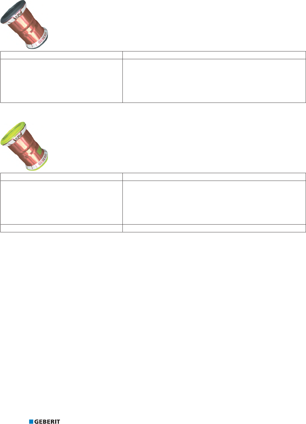
PRINCIPLES GEBERIT MAPRESS COPPER
70
Geberit Mapress Copper pressfitting with seal ring FKM, blue
Outer diameter 15–54 mm
Description • Pressfitting made of CuDHP copper, brass or gunmetal, for pressing quality
copper pipes according to EN/DVGW, for special applications, e.g. solar
applications
• Seal ring FKM, blue
• White pressing indicator
• Black protection plug
Geberit Mapress Copper pressfitting with seal ring HNBR, yellow
Outer diameter 15–54 mm
Description • Pressfitting made of CuDHP copper, brass or gunmetal, for pressing quality
copper pipes according to EN/DVGW, for gas installations (natural and
liquefied gases)
• Seal ring HNBR yellow
• White pressing indicator
• Yellow protection plug
Properties • Leaky if unpressed

PRINCIPLES GEBERIT MAPRESS COPPER
71
Fittings
Standard fittings
Figure87: Geberit Mapress Copper standard fittings
Adapters, permanent
Figure88: Geberit Mapress Copper adapter socket for connections from copper pipes to mild steel pipes
Figure89: Connections from Geberit FlowFit and Geberit Mepla to Geberit Mapress
Figure90: Geberit Mapress Copper adapters with male thread and adapters with female thread
Figure91: Geberit Mapress Copper elbow adapter 90°

PRINCIPLES GEBERIT MAPRESS COPPER
72
Adapters and connections, removable
Figure92: Geberit Mapress Copper adapters and adapter unions
Figure93: Geberit Mapress adapters with MasterFix
Figure94: Flange connections
Catches
Figure95: Geberit Mapress Copper cap
Connections
Figure96: Geberit connections, stainless steel and gunmetal
Figure97: Geberit connections for heating

PRINCIPLES GEBERIT MAPRESS COPPER
73
Accessories
The following accessories are available for Geberit Mapress Copper:
Figure98: Geberit insulation for connections
Figure99: Geberit contact protection, as a hose or adhesive tape, yellow
Figure100: Geberit sealing tape
CIIR, black HNBR, yellow FKM, blueEPDM, black
Figure101: Geberit Mapress seal rings
EPDM, black FPM, green Centellen 3822 Centellen 3825 Centellen 3822
Figure102: Geberit Mapress flat gaskets and flange gasket
Figure103: Geberit pipe fastenings
Figure104: Geberit fastenings for connections

PRINCIPLES GEBERIT MAPRESS COPPER
74
Pipe valve fittings
Figure105: Geberit Mapress stop valves
Figure106: Geberit Mapress concealed stop valves
Figure107: Geberit Mapress ball valves
Figure108: Geberit Mapress concealed ball valves
Figure109: Geberit Mapress Stainless Steel non-return valve, flanged
Further information on the different designs and applications as well as on various accessories such as actuator levers, handles and
spindle extensions can be found in the online or printed catalogue.
1.4.3 Marking of copper pipes according to EN
All copper pipes must be marked on the surface.
The marking according to EN 10088-2 contains following information in the order given:
• manufacturer
• brand
• outer diameter x wall thickness
• European standard
• DVGW test mark
• country of manufacture
• building material class
• thermal insulation according to the Energy Savings Act

PRINCIPLES GEBERIT MAPRESS COPPER
75
1.4.4 Application examples for fittings
Geberit Mapress Copper adapters, permanent
Figure110: Geberit FlowFit adapter to Geberit Mapress, with plain end
1 Geberit FlowFit adapter to Geberit Mapress, with plain end
2 Geberit Mapress system pipe
3 Geberit system pipe ML
Figure111: Connection to Geberit Mepla
1 Geberit Mepla adapter to Geberit Mapress, with plain end
2 Geberit Mepla system pipe
3 Geberit Mapress Copper pressfitting
Figure112: Connection to female thread
1 Geberit Mapress Copper adapter with male thread
2 Threaded socket with female thread
3 Geberit Mapress Copper system pipe
Figure113: Connection to stop valve
1 Geberit Mapress Copper adapter with male thread and plain end
2 Geberit Mapress Copper pressfitting (T-piece)
3 Angle-seat valve
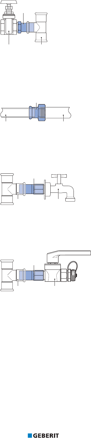
PRINCIPLES GEBERIT MAPRESS COPPER
76
Figure114: Connection to stop valve
1 Geberit Mapress Copper adapter with male thread and plain end
2 Geberit Mapress Copper pressfitting (T-piece)
3 Slide valves
Figure115: Connection to male thread
1 Geberit Mapress Copper adapter with female thread
2 Steel pipe with male thread
3 Copper pipe according to EN1057
Figure116: Connection to outside tap
1 Geberit Mapress Copper adapter with female thread and plain end
2 Outside tap with male thread
3 Geberit Mapress Copper pressfitting (T-piece)
Figure117: Connection to male thread
1 Geberit Mapress Copper adapter with union nut
2 Pipe valve fitting with male thread G (heating fill valve)
3 Geberit Mapress Copper T-piece
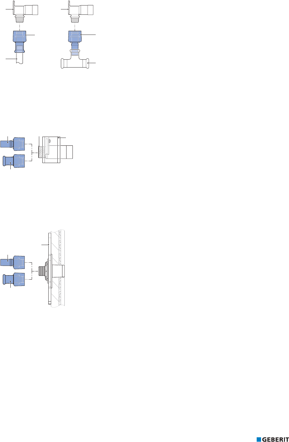
PRINCIPLES GEBERIT MAPRESS COPPER
77
Geberit Mapress Copper adapters and connections, removable
Figure118: Tool-free connection with MasterFix
1 Geberit Mapress adapter with MasterFix
2 Copper pipe according to EN1057
3 Fitting with male thread MF 1/2" (elbow tap connector 90°)
4 Geberit Mapress adapter with Geberit MasterFix and plain end
5 Geberit Mapress Copper pressfitting (T-piece)
Figure119: Tap connector, straight, with MasterFix
1 Geberit tap connector, straight, with male thread MF 1/2"
2 Mounting plate, sound insulation set
3 Geberit Mapress adapter with MasterFix
4 Geberit Mapress adapter with MasterFix and plain end
Figure120: Tap connector, straight with Geberit MasterFix, drywall construction
1 Geberit tap connector set, straight, with male thread MF 1/2", premounted, drywall construction
2 Geberit Mapress adapter with MasterFix
3 Geberit Mapress adapter with MasterFix and plain end

PRINCIPLES GEBERIT MAPRESS COPPER
78
Figure121: Connection to male thread
1 Geberit Mapress Copper adapter with union nut
2 Pipe valve fitting with male threadG
3 Copper pipe according to EN1057
Figure122: Connection to male thread
1 Copper pipe according to EN1057
2 Geberit Mapress Copper adapter with union nut
3 Circulation pump with male threadG
Figure123: Connection to corrugated pipes
1 Geberit Mapress adapter union with clamping ring for corrugated pipes, non-potable water, plain end
2 Corrugated pipe
3 Geberit Mapress Copper pressfitting (threaded socket)

PRINCIPLES GEBERIT MAPRESS COPPER
79
Geberit Mapress Copper adapters and connections (gas)
Figure124: Adapter to cutting ring connection
1 Geberit Mapress Copper adapter to cutting ring connection (gas)
2 Cutting ring connection
3 Copper pipe according to EN1057
Figure125: Connection to gas valves, conical-sealing
1 Geberit Mapress Copper adapter with union nut (gas)
2 Gas meter
3 Copper pipe according to EN1057
Figure126: Connection for two-pipe gas meter
1 Geberit Mapress Copper elbow tap connector90°, offset, circular hole 50mm (gas)
2 Mounting bracket for gas meter
3 Copper pipe according to EN1057

PRINCIPLES GEBERIT MAPRESS COPPER
80
Geberit Mapress Copper connections for heating
Figure127: Radiator connection for pipe laying with a distance to the wall
1 Geberit Mapress metal pipe connector bend 90° with insulation box and union connector for Euro cone
2 Geberit Mapress Carbon Steel pipe nipple, outside zinc-plated
3 Geberit Mapress T-piece crossing with insulation box
4 Copper pipe according to EN1057 (inlet / return flow)
Figure128: Radiator connection for pipe laying near the wall
1 Geberit Mapress metal pipe connection T-piece with insulation box and union connector for Euro cone
2 Copper pipe according to EN1057 (inlet / return flow)

PRINCIPLES GEBERIT MAPRESS COPPER
81
Figure129: Connection for surface-mounted pipe (skirting board), with a distance between the inlet and return flow
1 Geberit Mapress Copper T-piece, reduced
2 Copper pipe according to EN1057 (inlet / return flow)
3 Geberit Mapress Copper connector T-piece set for return flow
Figure130: Connection for surface-mounted pipe (skirting board), with connector 4cm
1 Geberit Mapress Copper connector T-piece for inlet and return flow
2 Copper pipe according to EN1057 (inlet / return flow)
Figure131: Connection for surface-mounted pipe (skirting board), with extendible connector
1 Geberit Mapress Copper connector T-piece set for inlet and return flow
2 Copper pipe according to EN1057 (inlet / return flow)

PRINCIPLES GEBERIT MAPRESS COPPER
82
Figure132: Skirting board connection with adapter with union connector for Euro cone
1 Geberit Mapress Copper connector T-piece set for inlet and return flow, with union connector for Euro cone
2 Copper pipe according to EN1057 (inlet / return flow)
Figure133: Union connector for Euro cone
1 Geberit adapter with union connector for Euro cone
2 Copper pipe according to EN1057 (inlet / return flow)
3 Valve tap block with Euro cone
Figure134: Radiator connector box type C for higher screed constructions
1 Geberit Mapress connector box type C
2 Geberit Mapress T-piece crossing with insulation box

PRINCIPLES GEBERIT MAPRESS COPPER
83
Figure135: Radiator connector box type L for low screed constructions
1 Geberit Mapress connector box type L
2 Geberit Mapress T-piece crossing with insulation box
3 Copper pipe according to EN1057 (inlet / return flow)
4 Geberit Mapress threaded socket
PRINCIPLES GEBERIT MAPRESS COPPER
84
1.4.5 System characteristics
The following table gives an overview of the most important system characteristics of Geberit Mapress Copper:
Characteristic Meaning
Diffusion barrier Geberit Mapress Copper fittings and pressed joints form a barrier against diffusion.
Hot water resistance Permanent 0‒100°C
Resistance to cold Down to -30°C provided that the medium in the pipe does not freeze.
Material abrasion If the recommended flow rate is observed, no material abrasion occurs in the pipe.
UV resistance UV-resistant
Corrosion resistance Largely corrosion-resistant in normal, dry environments as well as against a variety
of liquids and gaseous media. Corrosion protection is required in the event of contact
with building materials containing sulphides, nitrites and ammonium, as well as in the
case of installation in an aggressive environment.
Electrical conductivity Electrically conductive, must be integrated into the main equipotential bonding.
Transmission of structure-borne
sound
In the case of decoupling from the building structure, there is no transmission of
structure-borne sound.
Fire behaviour Copper pipes are non-combustible.
1.4.6 Certificates for Geberit Mapress Copper
The Geberit Mapress Copper systems have certificates from the following bodies, amongst others.
Certification body Application
DVGW Drinking water installations, gas installations
ÖVGW
BSI
CSTB Drinking water installations
WRAS
IMQ Gas installations
KIWA-NL
TÜV TÜV component certificate with a supplementary expert report for industrial applications
DIBt Industrial applications
ABS Shipbuilding
BV
CCS
RINA
RMRS

PRINCIPLES GEBERIT MAPRESS COPPER
85
1.4.7 Technical data
Copper pipes
The Geberit Mapress Copper range does not contain any pipes. The copper pipes according to EN1057:2006+A1:2010 and DVGW
GW 392:2015-04 listed in this product information are, however, part of the certification testing of Geberit Mapress Copper.
Copper pipes according to EN1057
Product material and product material characteristics
Table39: Material of copper pipes according to EN1057
Strength
(EN1173)
Material designation Abbreviation Material number
EN UNS
R220 (annealed)
Copper Cu-DHP CW024A C12200R250 (half hard)
R290 (hard)
Table40: Physical properties of copper pipes according to EN1057
Strength Tensile strength
min
Elongation at break
min
(EN1173) R
m
[MPa]
A
[%]
R220 (annealed) 220 40
R250 (half hard) 250 20
R290 (hard) 290 3

PRINCIPLES GEBERIT MAPRESS COPPER
86
Pipe data
G
GL
V
Table41: Copper pipes according to EN1057
DN d
[mm]
s
[mm]
di
[mm]
Strength
(EN1173)
R220
(annealed)
R250
(half hard)
R290
(hard)
10
12 0.6 10.8
12 0.8 10.4
12 1.0 10.0
12
15 0.7 13.6
15 1.0 13
20
22 0.9 20.2
22 1.2 19.6
25
28 0.9 26.2
28 1.2 25.6
32
35 1.0 33
35 1.2 32.6
35 1.5 32
40
42 1.0 40
42 1.2 39.6
42 1.5 39
50
54 1.0 52
54 1.2 51.6
54 1.5 50
60 66.7 1.2 64.3
65
76.1 1.5 73.1
76.1 2.0 72.1
100
108 1.5 105
108 2.5 103
Admissible, suitable for pressing
Inadmissible, not suitable for pressing

PRINCIPLES GEBERIT MAPRESS COPPER
87
Copper pipes according to DVGWGW392
Product material and product material characteristics
Table42: Material of copper pipes according to DVGW GW 392:2015-04 ( EN1057)
Strength
(EN1173)
Material designation Abbreviation Material number
EN UNS
R220 (annealed)
Copper Cu-DHP CW024A C12200R250 (half hard)
R290 (hard)
Table43: Physical properties of copper pipes according to DVGW GW 392:2015-04 (EN1057)
Strength Tensile strength
min
Elongation at break
min
(EN1173) R
m
[MPa]
A
[%]
R220 (annealed) 220 40
R250 (half hard) 250 20
R290 (hard) 290 3
Pipe data
G
GL
V
Table44: Copper pipes according to DVGW GW 392:2015-04 (in accordance with EN1057 and EN13349)
DN d
[mm]
s
[mm]
di
[mm]
Strength
(EN1173)
R220
(annealed)
R250
(half hard)
R290
(hard)
10
12 0.8 10.4
12 1.0 10
12 15 1.0 13
15 18 1.0 16
20 22 1.0 20
25
28 1.0 26
28 1.5 25
32
35 1.2 32.6
35 1.5 32
40
42 1.2 39.6
42 1.5 39
50
54 1.5 51
54 2.0 50
65 76.1 2.0 72.1
80 88.9 2.0 84.9
100 108 2.5 103
Available
Not available

PRINCIPLES GEBERIT MAPRESS COPPER
88
Pressfittings
Product material and product material characteristics
Table45: Material of Geberit Mapress Copper pressfitting
Material designation Copper
Abbreviation Cu-DHP
Material number EN CW024A
Material number UNS C12200
Table46: Material of Geberit Mapress Copper pressfittings, gunmetal
Material designation Gunmetal
Abbreviation CuSn5Zn5Pb2-C
Material number EN CC499K
Material number UNS
1)
1) No number according to the Unified Numbering System (UNS)
Table47: Material of Geberit Mapress Copper pressfitting, DR brass
Material designation DR brass
Abbreviation CuZn36Pb2As
Material number EN CW602N
Material number UNS C35330
Table48: Material of Geberit Mapress Copper pressfitting, brass
Material designation Brass
Abbreviation CuZn40Pb2
Material number EN CW617N
Material number UNS C38000
For information on the recycling code of the pressing indicator and protection plug, see the ‘Disposal’ chapter.
Table49: Physical properties of Geberit Mapress Copper pressfitting
Thermal expansion coefficient α at 20–100°C 16.6·10
-6
m/(m•K)
Thermal conductivity λ at 20°C 305W/(m•K)
Specific thermal capacity c at 20 °C 386J/(kg•K)
Surface roughness k 0.001mm
Building material class EN13501 A1
DIN 4102 Part1 A1

PRINCIPLES GEBERIT MAPRESS COPPER
89
System seals
Material and temperature resistance
Table50: Geberit Mapress seal rings for Geberit Mapress Copper
CIIR, black EPDM, black HNBR, yellow FKM, blue
d
[mm]
12–54 66.7–108 15–54 12–54
Material
Chlorinated butyl
rubber
Ethylene propylene
diene monomer
rubber
Hydrogenated
acrylonitrile-butadiene
rubber
Fluoro rubber
Operating temperature
1)
[°C]
-30–+120 -30–+120 -20–+70 -25–+140
2)
-25–+180
3)
Leaky if unpressed
Applies
Does not apply
1) Additional information on the operating temperatures, together with the uses and operating pressures, is given in the respective
usage overviews. The current usage overviews can be found in the online catalogue or in the printed catalogue.
2) Use only approved antifreeze agent according to the "Corrosion and antifreeze agent” technical information.
3) When used in thermal media (solar): Service life with collector downtime: 200h/a at 180°C, 60h/a at 200°C, total service life:
500h at 220°C.
Table51: Geberit Mapress flat gaskets for Geberit Mapress Copper
EPDM,
black
FPM,
green
Centellen®
HDWS3822
Centellen®
HDWS3825
G 1/2 to 23/8˝ 3/4 to 23/8˝ 3/4 to 23/8˝ 1/2 to 31/2˝
Material
Ethylene propylene
diene monomer rubber
Fluoro rubber
Aramid fibres with
inorganic reinforcing
materials and rubber as
a binding material
Aramid fibres with
inorganic reinforcing
materials and rubber as
a binding material
Operating temperature
1)
[°C]
0–100 -30–+180 -20–+155 -30–+150
1) Additional information on the operating temperatures, together with the uses and operating pressures, is given in the respective
usage overviews. The current usage overviews can be found in the online catalogue or in the printed catalogue.
Table52: Geberit Mapress flange gasket and O-rings for Geberit Mapress Copper
Geberit Mapress flange gasket
Centellen® HD WS 3822
O-rings for Geberit Mapress screw
connections, conical-sealing, gas
Nominal width
DN
15–100
G
7/8, 11/8 and 13/8˝
Material Aramid fibres with inorganic reinforcing materials
and rubber as a binding material
Hydrogenated acrylonitrile-butadiene rubber
Operating temperature
[°C]
-30–+180 -20–+70
Does not apply

PRINCIPLES GEBERIT MAPRESS COPPER
90
The operating conditions specified in the relevant approvals, standards and technical regulations must be observed for each
application. These may differ from the information in the usage overviews.
Maximum axial load of pressed joints
The following maximum axial loads apply when using Geberit Mapress Copper pressed joints:
Table53: Maximum axial load of the pressed joint for connections with copper pipes with different strengths (R) according to EN 1173
Pressing attachment d
[mm]
s
[mm]
Maximum axial load
[N]
R220 R250 R250
Pressing jaw with
compatibility [2]/[3]
12 1.0 600 900 900
15 1.0 800 1000 1000
18 1.0 1000 1000 1100
22 1.0 1000 1100 1600
28 1.5 1400 2200
35 1.2 1600
Pressing collar with
compatibility [2]/[3]/[2XL]
35 1.5
42 2.0 3800
54 2.0 4800
66.7 1.2 11900
76.1 2.0 14000
88.9 2.0 17600
108 2.5 34800
Does not apply

PRINCIPLES GEBERIT MAPRESS CUNIFE
91
1.5 GEBERIT MAPRESS CUNIFE
1.5.1 Overview of Geberit Mapress CuNiFe
Geberit Mapress CuNiFe is a supply system in which pipes and fittings made of a copper-nickel-iron alloy (CuNiFe) are pressed to form
permanent, technically tight pipes.
Due to its excellent corrosion resistance to seawater, Geberit Mapress CuNiFe is suitable for applications that come into contact with
seawater. The system covers many applications in the (offshore) industry and in shipbuilding due to the wide range of possible
combinations of pipes, fittings and seal rings.
The most common uses for Geberit Mapress CuNiFe are listed below. Other applications (media), together with the operating
temperatures and operating pressures, are listed in the respective usage overviews.
The current usage overviews can be found in the online catalogue or in the printed catalogue.
The operating conditions specified in the relevant approvals, standards and technical regulations must be observed for each
application. These may differ from the information in the usage overviews.
Seal ring Fitting System pipe Combined pipe and fitting
dimensions
Most common uses
CIIR, black
CuNi10Fe1.6Mn
CuNi10Fe1.6Mn
d15‒108mm
• Cooling water
• Service water
• Grey and black water with a pH value <6.0
• Seawater
• Wet extinguishing water
• Wet/dry sprinklers
• Bilges
1.5.2 System components
The Geberit Mapress CuNiFe system consists of the following components:
• system pipes
• fittings with system seals
• pipe valve fittings
• accessories
• tools

PRINCIPLES GEBERIT MAPRESS CUNIFE
92
System pipes
Geberit Mapress CuNiFe system pipe
Outer diameter 15–108 mm
Description • Material CuNi10Fe1.6Mn
• Material number 2.1972.11
• With a black protection plug
Additional features guaranteed by the Geberit
works standard
• Seamlessly drawn
Properties • When exposed to clean seawater, it forms a natural thin protective coating
predominantly of copper oxide, which makes the pipe corrosion-resistant
• Bendable from d15–108mm
1)
1) Can be bent by hand up to a pipe diameter of d28mm. Special pipe bending machines are required for bending from a diameter of
d35mm.
Pressfittings
Geberit Mapress CuNiFe pressfitting with seal ring CIIR, black
Outer diameter 15–108 mm
Description • Pressfitting made of CuNi10Fe1.6Mn for industry and shipbuilding
• Translucent protection plug
• Black pressing indicator
• Seal ring CIIR, black
Properties • Leaky if unpressed
Geberit Mapress CuNiFe pressfitting with seal ring FKM, blue
Outer diameter d15–108mm
Description • Pressfitting made of CuNi10Fe1.6Mn for shipbuilding
• Black protection plug
• Black pressing indicator
• Seal ring FKM, blue
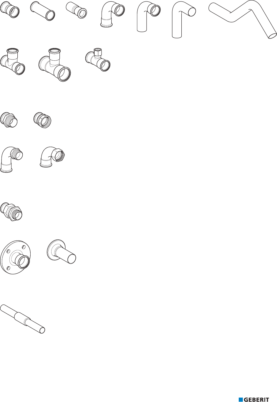
PRINCIPLES GEBERIT MAPRESS CUNIFE
93
Fittings
Standard fittings
Figure136: Geberit Mapress CuNiFe standard fittings
Adapters, permanent
Figure137: Geberit Mapress CuNiFe adapters with male thread and adapters with female thread
Figure138: Geberit Mapress CuNiFe bend adapters 90°
Adapters and connections, removable
Figure139: Geberit Mapress CuNiFe adapter union
Figure140: Flange connections
Bulkhead and deck passing
Figure141: Geberit Mapress CuNiFe bulkhead and deck passing

PRINCIPLES GEBERIT MAPRESS CUNIFE
94
Accessories
The following accessories are available for Geberit Mapress CuNiFe:
CIIR, black FKM, blue
Figure142: Geberit Mapress seal rings
EPDM, black FPM, green Centellen 3822 Centellen 3825 Centellen 3822
Figure143: Geberit Mapress flat gaskets and flange gasket
Figure144: Geberit pipe fastenings
Figure145: Geberit fastenings for connections

PRINCIPLES GEBERIT MAPRESS CUNIFE
95
1.5.3 Marking of Geberit Mapress CuNiFe system pipes
The marking of Geberit Mapress CuNiFe system pipes includes the information in the table in the order shown. A pipe with a dimension
of d28 mm is used as an example.
Eucaro10 Manufacturer's material designation
MAPRESS Product name
DIN86019 DIN standard: Seamless pipes made of CuNi10Fe1.6Mn for pipelines
CuNi10Fe1.6MN Short material designation
28x1.5 Outer pipe diameter and wall thickness [mm]
CHRNO xxxx Melt number
1.5.4 System characteristics
The following table gives an overview of the most important system characteristics of Geberit Mapress CuNiFe:
Characteristic Meaning
Diffusion barrier Geberit Mapress CuNiFe fittings, pipes and pressed joints form a barrier against
diffusion.
Hot water resistance Permanent 0‒100°C
Resistance to cold Down to -30°C under the condition that the medium in the pipe does not freeze
Material abrasion If the recommended flow rate is observed, no material abrasion occurs in the pipe.
UV resistance Geberit Mapress CuNiFe is UV-resistant and therefore also suitable for outdoor use.
Corrosion resistance Largely corrosion-resistant, especially to seawater and also to a variety of liquids and
gaseous media
Electrical conductivity Electrically conductive, must be integrated into the main equipotential bonding.
Transmission of structure-borne
sound
In the case of decoupling from the building structure, there is no transmission of
structure-borne sound.
Fire behaviour Geberit metal pipes are non-combustible.
1.5.5 Geberit Mapress CuNiFe certificates
The Geberit Mapress CuNiFe system has certificates from the following bodies, amongst others:
Certification body Application
ABS Shipbuilding
BV
CCS
DNV
LRS
RINA
RMRS

PRINCIPLES GEBERIT MAPRESS CUNIFE
96
1.5.6 Technical data
Geberit Mapress CuNiFe system pipe
Product material and product material characteristics
Table54: Material
Material designation Copper-nickel forging alloy
Short name according to EN10088 CuNi10Fe1.6Mn
Material number 2.1972.11
Table55: Physical characteristics
Thermal expansion coefficient α at 20–100°C 0.017mm/(m·K)
Thermal conductivity λ at 20°C 50 W/(m·K)
Specific thermal capacity c at 20 °C 377 J/(kg·K)
Surface roughness k 10µm
Building material class EN13501 A1
DIN 4102 Part1 A1
Table56: Mechanical characteristics
Tensile strength R
m
300-400N/mm
2
0.2% expansion limit R
p0.2
100-180N/mm
2
Elongation at break A
5
>30%
Pipe data
G
GL
V
Table57: Geberit Mapress CuNiFe system pipe 2.1972.11
DN d
[mm]
s
[mm]
di
[mm]
m
R
[kg/m]
m
RW
[kg/m]
V
[l/m]
12 15 1 13 0.390 0.530 0.133
20 22 1 20 0.590 0.910 0.314
20 22 1.5 19 0.860 1.150 0.284
25 28 1.5 25 1.110 1.610 0.491
32 35 1.5 32 1.410 2.230 0.804
40 42 1.5 39 1.700 2.920 1.195
50 54 1.5 51 2.210 4.300 2.043
65 76.1 2 72.1 4.140 8.320 4.083
80 88.9 2 84.9 4.870 10.660 5.661
100 108 2.5 104 7.380 15.910 8.332
m
R
Pipe weight
m
RW
Pipe weight with water 25°C, salt content 35g/kg, pressure 1 atm
V Pipe volume

PRINCIPLES GEBERIT MAPRESS CUNIFE
97
Geberit Mapress CuNiFe pressfitting
Product material and product material characteristics
Table58: Material
Material designation Copper-nickel forging alloy
Abbreviation CuNi10Fe1.6Mn
Material number DIN 2.1972
For information on the recycling code of the pressing indicator and protection plug, see the ‘Disposal’ chapter.
System seals
Material and temperature resistance
Table59: Geberit Mapress seal rings for Geberit Mapress CuNiFe
CIIR, black FKM, blue
d
[mm]
15–108 15–108
Material Chlorinated butyl rubber Fluoro rubber
Operating temperature
1)
[°C] -30–+120 -25–+140
2)
Leaky if unpressed
Applies
Does not apply
1) Additional information on the operating temperatures, together with the uses and operating pressures, is given in the respective
usage overviews. The current usage overviews can be found in the online catalogue or in the printed catalogue.
2) Use only approved antifreeze agent according to the "Corrosion and antifreeze agent” technical information.

CHAPTER TWO
PRACTICAL USE
98

PRACTICAL USE GENERAL
99
2.1 GENERAL
2.1.1 Disinfection of drinking water installations
Principles
Drinking water installations must only be disinfected in proven cases of contamination and only for a limited time. Prophylactic
disinfection contradicts the principle of minimisation of the Drinking Water Inspectorate. Disinfection of drinking water installations is
only successful when all sources of contamination have been removed. The limit values for disinfectant concentrations specified in the
Drinking Water Inspectorate are maximum values, which were set with due consideration of hygienic and toxicological viewpoints. They
do not allow any automatic conclusions to be drawn about the resistance of the materials used to disinfectants. Drinking water
installations may only be disinfected by skilled persons. The disinfection measures must be recorded in writing.
The disinfection measures place a strain on the materials and components of the potable water installation and may adversely
affect its service life. Disinfection measures carried out incorrectly can damage the potable water installation.
BS8558 and BSEN806 provide guidance on materials, water quality and cleaning and disinfection, which should be read in
conjunction with the information contained here.
Methods of disinfection
Drinking water installations and washbasin taps can be disinfected using thermal or chemical methods. Drinking water can also be
disinfected by means of UV radiation.
A combined thermal-chemical disinfection is not admissible.
Thermal disinfection
In the case of thermal disinfection, microorganisms that are found in water are killed off by the effects of temperature.
The following rules must be observed during thermal disinfection:
• The piping system must be thoroughly rinsed before the disinfection process is performed.
• The water heater and the entire circulation must be heated up to at least 70°C.
• All points of use must be opened step by step or line by line respectively.
• Hot water must be allowed to run at all points of use for at least 3 minutes at 70°C.
• The temperatures must not decrease during the disinfection process.
• Risk of scalding must be eliminated by taking suitable measures.
• Performance of the disinfection process must be documented in a report.
Chemical disinfection
Effective killing or inactivation of microorganisms is only possible if the disinfectant used can act on the microorganisms directly. In the
case of chemical disinfection, a disinfectant is therefore used in a sufficient concentration in all areas of the drinking water installation.
A distinction is made between the following chemical disinfection techniques:
• system disinfection
• drinking water disinfection
Chemical disinfectants corrode the drinking water installation and must only be used in the event of contamination.
Using a combination of several chemical disinfectants is not admissible.
Chemical disinfection can be performed several times throughout the service life of the drinking water installation. The
disinfection measures, however, place a strain on the materials and components of the drinking water installation and may
adversely affect its service life. It is not possible to provide a specification on the reduction in service life depending on the
number of chemical disinfections performed.

PRACTICAL USE GENERAL
100
System disinfection
For system disinfection, a disinfectant in a high concentration is added to a cold-water pipe over a short period of time.
Geberit piping systems and Geberit washbasin taps are suitable for system disinfection.
The following rules apply when carrying out system disinfection:
• Concentrations, temperatures and application times of the permitted disinfectants must be adhered to in strict compliance with
country-specific regulations.
• Skilled persons must take specific measuring and control technology precautions.
• To prevent increases in concentration, the specific characteristics of the affected drinking water installation must be taken into
account.
• Concentrations, temperatures and application times must be documented.
• Cleaning and disinfection measures must be recorded.
• To remove disinfectant and dead germs after disinfection is complete, the drinking water installation must be flushed thoroughly
with hygienically perfect drinking water.
• All points of use must be flushed until the limit value of the Drinking Water Inspectorate is reached.
• No drinking water may be consumed during disinfection and the subsequent flushing phase.
Drinking water disinfection
For drinking water disinfection, a disinfectant in a low concentration is added to the drinking water pipe (cold or hot) for a limited time.
Geberit piping systems and Geberit washbasin taps are suitable for time-limited drinking water disinfection.
The following rules apply when carrying out drinking water disinfection:
• Concentrations, temperatures and the duration of application of the permitted disinfectants must be adhered to in strict compliance
with the country-specific regulations.
• Skilled persons must take specific measuring and control technology precautions.
• To prevent increases in concentration, the specific characteristics of the affected drinking water installation must be taken into
account.
• Concentrations, temperatures and by-products must be monitored and documented directly after the dosing point using
measurement technology.
• The concentration of the agent in the treated water must be measured daily.
• The drinking water disinfection must be kept as short as possible and it should last no longer than it takes for the technical
rehabilitation to be realised.
Exceeding the concentration for use and duration can adversely affect the service life of the piping system.
UV disinfection
Geberit Mapress piping systems
Geberit Mapress piping systems are suitable for UV disinfection without restriction.

PRACTICAL USE GENERAL
101
2.1.2 Geberit piping systems for treated water
Table60: Use of Geberit Mapress pipes for treated water
Use System pipes Fittings Seals
Geberit Mapress Stainless Steel
1.4401 / 316
Geberit Mapress Stainless Steel
1.4521 / 444
Geberit Mapress Stainless Steel
1.4301 / 304
Geberit Mapress Carbon Steel
1.0034
Copper
Stainless steel 1.4401/316
Gunmetal (CuSn5Zn5Pb2-C)
Brass (CW617N)
C-steel 1.0034
Copper (CU-DHP copper
CW024A)
CIIR, black
EPDM, black
Centellen
®
R WS 3825
Centellen
®
HD WS 3822
Softened water ≥5°dH
2) 2) 2)
Softened water <5°dH
2) 2) 1) 1) 2) 1)
Water in heating circuits in accordance with VDI
2035-1 (saline)
2) 2) 2)
Water in heating circuits in accordance with VDI
2035-1 (low-saline)
2) 2) 2)
Water in cold and cooling circuits in accordance with
BTGA Regulation 3.003 (saline)
2) 2) 2)
Water in cold and cooling circuits in accordance with
BTGA Regulation 3.003 (low-saline)
2) 2) 2)
Fully desalinated water
Level of purity 3
1)
Fully desalinated water
Level of purity 2
1)
Fully desalinated water
Level of purity 2+
1)
Fully desalinated water
Level of purity 1
Fully desalinated water
Level of purity 1+
Suitable
Not suitable
1) Upon request
2) For closed heating and cooling circuits

PRACTICAL USE GENERAL
102
2.1.3 Disposal
Recycling
At the end of its service life, the Geberit Mapress system can be broken down into its individual parts and recycled according to the
materials.
Table61: Recycling of Geberit Mapress
Component Material Recycling Remarks
System pipes CrNiMo steel 1.4401 Scrap metal Material collection by recycling
companies
System pipes CrMoTi steel 1.4521 Scrap metal
System pipes CrNi steel 1.4301 Scrap metal
System pipes Carbon steel 1.0034 Scrap metal
System pipes Carbon steel 1.0215 Scrap metal
System pipes CuNi10Fe1.6Mn Scrap metal
Fittings made of metal CrNiMo steel 1.4401 Scrap metal
Protective caps and plugs PE-LD/PE-HD Plastic recycling
Outer packaging HDPE
Cardboard box
Plastic recycling
Paper recycling
Recycling code for the pressing indicator and protection plug
Table62: Plastic elements in Geberit Mapress pressfittings
Plastic element Material designation Abbreviation Recycling code
Pressing indicator Multilayer film PET-PS-PET
3(7
Protection plug Polyethylene, low-density PE-LD
3(/'

PRACTICAL USE DETERMINATION OF THE PIPE DIMENSION
103
2.2 DETERMINATION OF THE PIPE DIMENSION
The aim of determining the pipe dimension is to supply the user with sufficient hygienically perfect drinking water under optimum
pressure conditions.
The determination of the pipe dimension has changed drastically in drinking water installations for the following reasons, amongst
others:
• increased number of points of use, e.g. due to there being several sanitary rooms in apartments
• falling occupancy rate per apartment
• new installation techniques
• different user behaviour
Country-specific standards and regulations need to be considered for the determination of the pipe dimension.
Depending on the applicable standards, the pipe dimensions can be determined using one of the following methods:
• simplified method
• calculation method
System-related loading unit tables are required for the simplified method.
Alternatively, Geberit offers the Geberit loading unit tables for the quick and easy determination of the pipe dimension in small and
medium-sized objects.
The pipe dimensions are calculated according to pressure loss with the calculation method.
2.2.1 Loading units
The loading unit is the basis for all calculation methods. It denotes the flow rate available at the connection point before the point of use
depending on the application purpose and the period of use. A loading unit corresponds to an outlet flow rate of 0.1l/s.
Table63: Loading units LU per consumer according to SVGW directive W3
Consumers with connection DN 15 (1/2") Q
A
cold
[l/s]
Q
A
hot
[l/s]
LU cold LU hot
WC cistern, drinks dispenser
0.1 1
Washbasin, washing trough, bidet, hairdresser shower 0.1 0.1 1 1
Household dishwasher
0.1 1
Household washing machine
0.2 2
Outlet tap for balcony
0.2 2
Shower, kitchen sink, sink, cleaner sink, pedestal and wall-hung sink 0.2 0.2 2 2
Automatic urinal water flush
0.3 3
Bathtub 0.3 0.3 3 3
Outlet tap for garden and garage
0.5 5
No hot water connection available
Q
A
Outlet flow rate
LU Loading unit (Loading Unit)
The following must be observed when determining the pipe dimension:
• Heating filling valves must not be included.
• Consumers with connections larger than 1/2" and / or special flow capacities must always be calculated according to pressure loss
in accordance with manufacturer specifications.

PRACTICAL USE DETERMINATION OF THE PIPE DIMENSION
104
2.2.2 Geberit loading unit tables
The Geberit loading unit tables for the Geberit drinking water supply systems are considered an alternative to the simplified method for
determining the pipe dimension according to SVGW directive W3 for drinking water installations, edition 2013.
The pressure conditions and maximum flow velocities specified in the SVGW W3 are adhered to in the Geberit loading unit tables
taking the following criteria into account:
• no points of use larger than specified in the loading unit table
• the peak flow must not be exceeded according to SVGW directive W3, edition 2013, diagram 1
• no continuous use (longer than 15 minutes)
• maximum height difference of 12m between distribution battery and highest point of use
• static pressure of 5bar after the water pressure reducing valve
• maximum 150LU and maximum 50m unwound pipe length for each stack from the distributor battery
Table64: Geberit Mapress system pipes
Total loading units LU
2 3 5 8 16 50 150
Largest loading unit LU 2 3 5
Pipe dimension d
a
[mm] 15 18 22 28 35
Inner diameter d
i
[mm] 13 16 19.6 25.6 32
Recommended pipe length [m] 15 9 7 – – – –
LU Loading Unit
2.2.3 Assignment of Geberit pipe dimensions to nominal widths
Table65: Nominal widths DN and corresponding outer diameters d of Geberit supply systems
DN Geberit Mepla
d [mm]
Geberit Mapress
d [mm]
Steel pipe
d [inches]
10 12 3/8
12 16 15
15 20 18 1/2
20 26 22 3/4
25 32 28 1
32 40 35 11/4
40 50 42 11/2
50 63 54 2
65 66.7 21/2
65 75 76.1 21/2
80 88.9 3
100 108 4
Not available

PRACTICAL USE THERMAL EXPANSION OF PIPES
105
2.3 THERMAL EXPANSION OF PIPES
Pipes expand differently due to thermal effects depending on the material. This thermal expansion is designated as change in length Δl.
The higher the temperature differences, the greater also the change in length.
The following affect the change in length:
• material
• ambient conditions
• operating conditions (e.g. media with different temperatures)
The change in length must be taken into account in the planning of the pipe installation.
In the case of pipes that are embedded in concrete in the protective tube or with the corresponding insulation, the thermal expansion is
absorbed within the protective tube or insulation. No further measures are therefore required.
The following designs must be taken into account for exposed or concealed installation and when laying pipes in ducts.
The pipes are kept flexible with guide brackets.
Anchor points direct the change in length in the desired direction. Suitable measures must be taken to absorb the change in length,
depending on the specification of the change in length.
2.3.1 Positioning of anchor points and guide brackets
The following rules must be observed for fastening pipes with anchor points (F) and guide brackets (GL):
• Anchor or guide brackets must not be attached to pressfittings.
• Guide brackets must be set so that they do not become unwanted anchor points during operation.
)
*/
• Guide brackets must be positioned so that horizontal pipes can expand.
*/
)

PRACTICAL USE THERMAL EXPANSION OF PIPES
106
• In the case of branch pipes or changes in direction, the change in length of the deflection leg provides the minimum distance of the
first guide bracket, see the designs for determining the deflection leg length.
• A pipe run that does not have an expansion compensator (e.g. change in direction, U-bend) may only include one anchor point.
) */*/
• For long pipe runs (e.g. riser pipes), it is recommended to position an anchor point in the middle of the pipe run. The expansion is
therefore routed in two directions and the load on the branch fittings is reduced.
• Branch discharge pipes (e.g. to radiators) must be sufficiently long to accommodate the change in length that occurs in the piping
system.
*/
*/
)

PRACTICAL USE ABSORPTION OF CHANGE IN LENGTH
107
2.4 ABSORPTION OF CHANGE IN LENGTH
Temperature-related changes in length Δl can be balanced out with the following measures:
Absorption of change in
length
Expansion
compensator
Expansion space
Axial expansion
fitting *
Deflection leg
Change in direction
U-bend
or insulation
* Only for Geberit Mapress Stainless Steel and Geberit Mapress Carbon Steel
2.4.1 Expansion space or insulation
Slight changes in the length of pipes can be absorbed by the elasticity of the piping system or by means of compressible insulation.
Figure146: Absorption of a change in length Δl by the elasticity of the piping system
Figure147: Absorption of a change in length Δl by means of compressible insulation

PRACTICAL USE ABSORPTION OF CHANGE IN LENGTH
108
2.4.2 Deflection legs as an expansion compensator
If the changes in length cannot be balanced out by means of the insulation, then the change in length must be absorbed by an
expansion compensator. Deflection legs are a type of expansion compensator. Planning for deflection legs means that no additional
costs and maintenance costs are incurred, for example, those that would arise through the installation of axial expansion fittings as an
expansion compensator.
Deflection legs can be used if there is a change in direction, for long straight pipes or as a U-bend.
/
%6
*/
*/)
*/
*/
)
/
%6
Figure148: Expansion compensation through change in direction
BS Deflection leg
F Anchor point
GL Guide bracket
L Pipe length
/
/
%6
)
)
*/ */ */ */
)
Figure149: Expansion compensation by a U-bend
BS Deflection leg
F Anchor point
GL Guide bracket
L Pipe length
The longer pipe section (L1 or L2) is used as the pipe length L to calculate the deflection leg length in the case of a U-bend.

PRACTICAL USE ABSORPTION OF CHANGE IN LENGTH
109
Deflection legs in riser pipes
In riser pipes over several floors, the thermal expansion is controlled with anchor points. The thermal expansion in several floor
connections is absorbed by means of deflection legs. The sliding brackets on horizontal pipes act like anchor points for the thermal
expansion of the pipe vertically.
/
/
/
/
/
/
+
/
/
)
*/
*/
*/
*/
*/
*/
*/
*/
*/
*/
*/
*/
*/
*/
*/
%6
%6
%6
%6
%6
%6
Figure150: Riser pipe with an anchor point in the middle: control of the thermal expansion upwards and downwards halves the deflection leg length
F Anchor point
BS Deflection leg
GL Guide bracket
L Pipe length
H1 Floor height

PRACTICAL USE ABSORPTION OF CHANGE IN LENGTH
110
*/
*/
*/
*/
*/
*/
*/
*/
*/
*/
*/
*/
*/
*/
*/
)
+
%6
%6
%6
%6
%6
%6
%6
/
/
/
/
/
/
/
/
Figure151: Riser pipe with an anchor point at the bottom: control of the thermal expansion upwards
F Anchor point
BS Deflection leg
GL Guide bracket
L Pipe length
H1 Floor height

PRACTICAL USE ABSORPTION OF CHANGE IN LENGTH
111
Deflection legs for pipe laying in a duct
If the pipe is laid in a duct, the change in length can be absorbed by deflection legs as follows:
%6
Figure152: Straight deflection leg, without insulation
BS Deflection leg
%6
Figure153: Bent deflection leg, without insulation
BS Deflection leg

PRACTICAL USE ABSORPTION OF CHANGE IN LENGTH
112
%6
6
Figure154: Straight deflection leg, with insulation
BS Deflection leg
S Insulation thickness
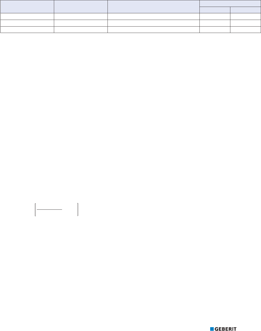
PRACTICAL USE ABSORPTION OF CHANGE IN LENGTH
113
Determination of the deflection leg length for Mapress Stainless Steel
The thermal expansion of pipes depends on the material, among other things. Expansion caused by material-dependent parameters
must be considered when calculating the deflection leg length. The following table lists the parameters for Geberit
Mapress Stainless Steel.
Table66: Material-dependent Geberit Mapress Stainless Steel parameters for calculating the deflection leg length
System pipe Material Thermal expansion coefficient
α [mm/(m•K)]
Material constant
C U
Stainless Steel 1.4401 CrNiMo steel 0.0165 60 34
Stainless Steel 1.4521 CrMoTi steel 0.0104 42 24
Stainless Steel 1.4301 CrNi steel 0.0160 58 33
C for calculating the deflection leg length L
B
(change in direction, branch pipe)
U for calculating the deflection leg length L
U
(U-bend)
The calculation of the deflection leg length comprises the following steps:
• calculation of the change in length Δl
• calculation of the deflection leg length L
B
with a change in direction and branch pipe or calculation of the deflection leg length L
U
with U-bends
Calculation of the change in length Δl
The change in length Δl is calculated with the following formula:
ୠ, /Ã̀Ãୠ7
Δl Change in length [mm]
L Pipe length [m]
ΔT Temperature differential (operating temperature ‒ ambient temperature at the time of installation) [K]
α Thermal expansion coefficient α [mm/(m • K)]
Given:
• Material: Stainless Steel 1.4401
• L=30m
• α=0.0165mm/(m•K)
• ΔT=50K
Required:
• Change in length Δl [mm]
Solution:
ୠ, /Ã̀Ãୠ7
PÃPPÃ.
PP
PÃ.
Δl= 30•0.0165•50
Δl = 24.75mm

PRACTICAL USE ABSORPTION OF CHANGE IN LENGTH
114
The change in lengthΔl can also be calculated in a simplified manner from the following table.
Table67: Change in length Δl [mm] for stainless steel 1.4401/1.4301
L
[m]
Temperature differential ∆T
[K]
10 20 30 40 50 60 70 80 90 100
1 0.17 0.33 0.50 0.66 0.83 0.99 1.16 1.32 1.49 1.65
2 0.33 0.66 0.99 1.32 1.65 1.98 2.31 2.64 2.97 3.30
3 0.50 0.99 1.49 1.98 2.48 2.97 3.47 3.96 4.46 4.95
4 0.66 1.32 1.98 2.64 3.30 3.96 4.62 5.28 5.94 6.60
5 0.83 1.65 2.48 3.30 4.13 4.95 5.78 6.60 7.43 8.25
6 0.99 1.98 2.97 3.96 4.95 5.94 6.93 7.92 8.91 9.90
7 1.16 2.31 3.47 4.62 5.78 6.93 8.09 9.24 10.40 11.55
8 1.32 2.64 3.96 5.28 6.60 7.92 9.24 10.56 11.88 13.20
9 1.49 2.97 4.46 5.94 7.43 8.91 10.40 11.88 13.37 14.85
10 1.65 3.30 4.95 6.60 8.25 9.90 11.55 13.20 14.85 16.50
20 3.30 6.60 9.90 13.20 16.50 19.80 23.10 26.40 29.70 33.00
30 4.95 9.90 14.85 19.80 24.75 29.70 34.65 39.60 44.55 49.00
40 6.60 13.20 19.80 26.40 33.00 39.60 46.20 52.80 59.40 66.00
50 8.25 16.50 24.75 33.00 41.25 49.50 57.75 66.00 74.25 82.50
L Pipe length
Table68: Change in length Δl [mm] for stainless steel 1.4521
L
[m]
Temperature differential ∆T
[K]
10 20 30 40 50 60 70 80 90 100
1 0.10 0.21 0.31 0.42 0.52 0.62 0.73 0.83 0.94 1.04
2 0.21 0.42 0.62 0.83 1.04 1.25 1.46 1.66 1.87 2.08
3 0.31 0.62 0.94 1.25 1.56 1.87 2.18 2.50 2.81 3.12
4 0.42 0.83 1.25 1.66 2.08 2.50 2.91 3.33 3.74 4.16
5 0.52 1.04 1.56 2.08 2.60 3.12 3.64 4.16 4.68 5.20
6 0.62 1.25 1.87 2.50 3.12 3.74 4.37 4.99 5.62 6.24
7 0.73 1.46 2.18 2.91 3.64 4.37 5.10 5.82 6.55 7.28
8 0.83 1.66 2.50 3.33 4.16 4.99 5.82 6.66 7.49 8.32
9 0.94 1.87 2.81 3.74 4.68 5.62 6.55 7.49 8.42 9.36
10 1.04 2.08 3.12 4.16 5.20 6.24 7.28 8.32 9.36 10.40
20 2.08 4.16 6.24 8.32 10.40 12.48 14.56 16.64 18.72 20.80
30 3.12 6.24 9.36 12.48 15.60 18.72 21.84 24.96 28.08 31.20
40 4.16 8.32 12.48 16.64 20.80 24.96 29.12 33.28 37.44 41.60
50 5.20 10.40 15.60 20.80 26.00 31.20 36.40 41.60 46.80 52.00
L Pipe length

PRACTICAL USE ABSORPTION OF CHANGE IN LENGTH
115
Calculation of the deflection leg length with a change in direction and branch pipe
The deflection leg length L
B
to be calculated is defined as follows with changes in direction and branch pipes:
ୠ,
/
%
*/
)
) */
Figure155: Expansion compensation with a change in direction
F Anchor point
GL Guide bracket
L
B
Deflection leg length
Δl Change in length
ୠ,
ୠ,
/
%
*/
*/
*/
Figure156: Expansion compensation with a branch pipe
GL Guide bracket
L
B
Deflection leg length
Δl Change in length
The deflection leg length L
B
is calculated using the following formula:
/
%
&Ã¥GÃୠ,
L
B
Deflection leg length [m]
d Outer pipe diameter [mm]
∆l Change in length [mm]
C Material constant

PRACTICAL USE ABSORPTION OF CHANGE IN LENGTH
116
Given:
• Material: Stainless Steel 1.4401
• C = 60
• d=54mm
• Δl = 28.88mm
Required:
• L
B
[m]
Solution:
&୰¥G୰ୠ,
/
%
P
PP
P
¥PPÃPP
/
%
P
Ã¥Ã
/
%
The deflection leg length L
B
can also be calculated in a simplified manner from the following graphics:
G
G
G
G
G
G
G
G
G
G
G
L [m]
B
Change in length Δl [mm]
Figure157: Deflection leg length L
B
, stainless steel 1.4401

PRACTICAL USE ABSORPTION OF CHANGE IN LENGTH
117
G
G
G
G
G
G
G
G
L [m]
B
Change in length Δl [mm]
Figure158: Deflection leg length L
B
, stainless steel 1.4521

PRACTICAL USE ABSORPTION OF CHANGE IN LENGTH
118
Calculation of the deflection leg length for U-bends
The deflection leg length L
U
to be calculated is defined as follows:
ୠ,
³
ୠ,
³
/
X
*/ */)
)
)
/
X
³
a
Figure159: U-bend, made of bent pipe
F Anchor point
GL Guide bracket
L
U
Deflection leg length
Δl Change in length
ୠ,
³
/
X
/
X
³
a
ୠ,
³
G
*/ */) )
)
Figure160: U-bend, made with pressfittings
F Anchor point
GL Guide bracket
L
U
Deflection leg length
Δl Change in length
The deflection leg length L
U
is calculated using the following formula:
8୰¥G୰ୠ,
/
8
L
U
Deflection leg length [m]
d Outer pipe diameter [mm]
∆l Change in length [mm]
U Material constant

PRACTICAL USE ABSORPTION OF CHANGE IN LENGTH
119
Given:
• Material: Stainless Steel 1.4401
• U = 34
• d=54mm
• Δl = 28.88mm
Required:
• L
U
[m]
Solution:
8୰¥G୰ୠ,
/
8
P
PP
P
¥PPÃPP
/
8
P
Ã¥Ã
/
8
The deflection leg length L
U
can also be calculated in a simplified manner from the following graphics:
G
G
G
G
G
G
G
G
G
G
G
L [m]
U
Change in length Δl [mm]
Figure161: Deflection leg length L
U
, stainless steel 1.4401
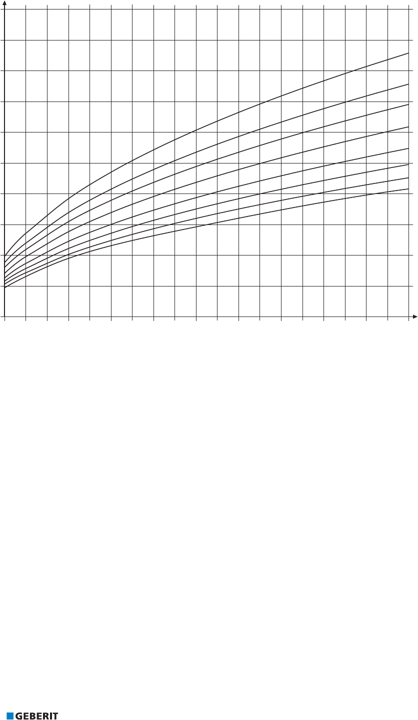
PRACTICAL USE ABSORPTION OF CHANGE IN LENGTH
120
G
G
G
G
G
G
G
G
L [m]
U
Change in length Δl [mm]
Figure162: Deflection leg length L
U
, stainless steel 1.4521

PRACTICAL USE ABSORPTION OF CHANGE IN LENGTH
121
Calculation of the deflection leg length for Mapress Carbon Steel
The thermal expansion of pipes depends on the material, among other things. Material-dependent parameters must be considered
when calculating the deflection leg length. The following table lists the parameters for Geberit Mapress Carbon Steel.
Table69: Material-dependent Geberit Mapress Carbon Steel parameters for calculating the deflection leg length
System pipe Material Thermal expansion coefficient α
[mm/(m•K)]
Material constant
C U
Geberit
Mapress Carbon Steel
1.0034
Non-alloy steel 0.012 55 31
C for calculating the deflection leg length L
B
(change in direction, branch pipe)
U for calculating the deflection leg length L
U
(U-bend)
The calculation of the deflection leg length comprises the following steps:
• Calculation of the change in length Δl
• Calculation of the deflection leg length L
B
with a change in direction and branch pipe or calculation of the deflection leg length L
U
with U-bends.
Calculation of the change in length Δl
The change in length Δl is calculated using the following formula:
ୠ, /Ã̀Ãୠ7
Δl Change in length [mm]
L Pipe length [m]
ΔT Temperature differential (operating temperature - ambient temperature at time of installation) [K]
α Thermal expansion coefficient α [mm/(m • K)]
Given:
• Material: Mapress Carbon Steel
• L= 30m
• α=0.012mm/(m•K)
• ΔT=50K
Required:
• change in lengthΔl[mm]
Solution:
ୠ, /Ã̀Ãୠ7
PÃPPÃ.
PP
PÃ.
Δl= 30•0.012•50
Δl = 18mm

PRACTICAL USE ABSORPTION OF CHANGE IN LENGTH
122
The change in length Δl can also be calculated in a simplified manner from the following table.
Table70: Change in length Δl in mm for Geberit Mapress Carbon Steel system pipes
L
[m]
Temperature differential ∆T
[K]
10 20 30 40 50 60 70 80 90 100
1 0.12 0.24 0.36 0.48 0.60 0.72 0.84 0.96 1.08 1.20
2 0.24 0.48 0.72 0.96 1.20 1.44 1.68 1.92 2.16 2.40
3 0.36 0.72 1.08 1.44 1.80 2.16 2.52 2.88 3.24 3.60
4 0.48 0.96 1.44 1.92 2.40 2.88 3.36 3.84 4.32 4.80
5 0.60 1.20 1.80 2.40 3.00 3.60 4.20 4.80 5.40 6.00
6 0.72 1.44 2.16 2.88 3.60 4.32 5.04 5.76 6.48 7.20
7 0.84 1.68 2.52 3.36 4.20 5.04 5.88 6.72 7.56 8.40
8 0.96 1.92 2.88 3.84 4.80 5.76 6.72 7.68 8.64 9.60
9 1.08 2.16 3.24 4.32 5.40 6.48 7.56 8.64 9.72 10.80
10 1.20 2.40 3.60 4.80 6.00 7.20 8.40 9.60 10.80 12.00
20 2.40 4.80 7.20 9.60 12.00 14.40 16.80 19.20 21.60 24.00
30 3.60 7.20 10.80 14.40 18.00 21.60 25.20 28.80 32.40 36.00
40 4.80 9.60 14.40 19.20 24.00 28.80 33.60 38.40 43.20 48.00
50 6.00 12.00 18.00 24.00 30.00 36.00 42.00 48.00 54.00 60.00
L Pipe length

PRACTICAL USE ABSORPTION OF CHANGE IN LENGTH
123
Calculation of the deflection leg length with a change in direction and branch pipe
The deflection leg length L
B
to be calculated is defined as follows with changes in direction and branch pipes:
ୠ,
/
%
*/
)
) */
Figure163: Expansion compensation with a change in direction
F Anchor point
GL Guide bracket
L
B
Deflection leg length
Δl Change in length
ୠ,
ୠ,
/
%
*/
*/
*/
Figure164: Expansion compensation with branch pipe
GL Guide bracket
L
B
Deflection leg length
Δl Change in length
The deflection leg length L
B
is calculated using the following formula:
/
%
&Ã¥GÃୠ,
L
B
Deflection leg length [m]
d Outer pipe diameter [mm]
∆l Change in length [mm]
C Material constant

PRACTICAL USE ABSORPTION OF CHANGE IN LENGTH
124
Given:
• Material: Mapress Carbon Steel
• C = 55
• d=54mm
• Δl = 21mm
Required:
• L
B
[m]
Solution:
&୰¥G୰ୠ,
/
%
P
PP
P
¥PPÃPP
P
/
%
P
Ã¥Ã
/
%
The deflection leg length L
B
can also be calculated in a simplified manner from the following graphics:
G
G
G
G
G
G
G
G
G
G
G
G
L [m]
B
Change in length Δl [mm]
Figure165: Deflection leg length L
B
, Geberit Mapress Carbon Steel

PRACTICAL USE ABSORPTION OF CHANGE IN LENGTH
125
Calculation of the deflection leg length for U-bends
The deflection leg length L
U
to be calculated is defined as follows:
ୠ,
³
ୠ,
³
/
X
*/ */)
)
)
/
X
³
a
Figure166: U-bend, made of bent pipe
F Anchor point
GL Guide bracket
L
U
Deflection leg length
Δl Change in length
ୠ,
³
/
X
/
X
³
a
ୠ,
³
G
*/ */) )
)
Figure167: U-bend, made with pressfittings
F Anchor point
GL Guide bracket
L
U
Deflection leg length
Δl Change in length
The deflection leg length L
U
is calculated using the following formula:
8୰¥G୰ୠ,
/
8
L
U
Deflection leg length [m]
d Outer pipe diameter [mm]
∆l Change in length [mm]
U Material constant

PRACTICAL USE ABSORPTION OF CHANGE IN LENGTH
126
Given:
• Material: Mapress Carbon Steel
• U = 31
• d=54mm
• Δl = 21mm
Required:
• L
U
[m]
Solution:
8୰¥G୰ୠ,
/
8
P
PP
P
¥PPÃPP
/
8
P
Ã¥Ã
/
8
The deflection leg length L
U
can also be calculated in a simplified manner from the following graphics:
G
G
G
G
G
G
G
G
G
G
G
G
L [m]
U
Change in length Δl [mm]
Figure168: Deflection leg length L
U
, Geberit Mapress Carbon Steel

PRACTICAL USE ABSORPTION OF CHANGE IN LENGTH
127
Determination of the deflection leg length for Mapress Copper
The thermal expansion of pipes depends on the material, among other things. Material-dependent parameters must be considered
when calculating the deflection leg length. The following table lists the parameters for Geberit Mapress Copper.
Table71: Material-dependent parameters for determining the deflection leg length for Geberit Mapress Copper
Pipe material System pipe Thermal expansion
coefficient α
[mm/(m•K)]
Material constant
C U
Copper Geberit Mapress Copper 0.0166 52 29
C for calculating the deflection leg length L
B
(change in direction, branch pipe)
U for calculating the deflection leg length L
U
(U-bend)
The calculation of the deflection leg length comprises the following steps:
• Calculation of the change in length Δl
• Calculation of the deflection leg length L
B
with a change in direction and branch pipe or calculation of the deflection leg length L
U
with U-bends.
Calculation of the change in length Δl
The change in length is calculated using the following formula:
ୠ, /Ã̀Ãୠ7
Δl Change in length [mm]
L Pipe length [m]
ΔT Temperature differential (operating temperature–ambient temperature at the time of installation) [K]
α Thermal expansion coefficient α [mm/(m • K)]
Given:
• Material: Copper
• L=30m
• α=0.0166mm/(m•K)
• ΔT=50K
Required:
• Change in length Δl [mm]
Solution:
ୠ, /Ã̀Ãୠ7
PÃPPÃ.
PP
PÃ.
Δl= 30• 0.0166 • 50
Δl = 24.9mm

PRACTICAL USE ABSORPTION OF CHANGE IN LENGTH
128
The change in length Δl can also be calculated in a simplified manner from the following tables.
Table72: Change in length Δl in mm for copper pipes
L
[m]
Temperature differential ΔT
[K]
10 20 30 40 50 60 70 80 90 100
1 0.1 0.3 0.5 0.7 0.8 1.0 1.2 1.3 1.5 1.7
2 0.3 0.7 1.0 1.3 1.7 2.0 2.3 2.7 3.0 3.3
3 0.5 1.0 1.5 2.0 2.5 3.0 3.5 4.0 4.5 5.0
4 0.7 1.3 2.0 2.7 3.3 4.0 4.7 5.3 6.0 6.6
5 0.8 1.7 2.5 3.3 4.2 5.0 5.8 6.6 7.5 8.3
6 1.0 2.0 3.0 4.0 5.0 6.0 7.0 8.0 9.0 10.0
7 1.2 2.3 3.5 4.6 5.8 7.0 8.1 9.3 10.5 11.6
8 1.3 2.7 4.0 5.3 6.6 8.0 9.3 10.6 12.0 13.3
9 1.5 3.0 4.5 6.0 7.5 9.0 10.5 12.0 13.5 15.0
10 1.7 3.3 5.0 6.6 8.3 10.0 11.6 13.3 14.9 16.6
20 3.3 6.6 10.0 13.3 16.6 19.9 23.2 26.6 29.9 33.2
30 5.0 10.0 14.9 19.9 24.9 29.9 34.9 39.8 44.8 49.8
40 6.6 13.3 19.9 26.6 33.2 39.8 46.5 53.1 59.8 66.4
50 8.3 16.6 24.9 33.2 41.5 49.8 58.1 66.4 74.7 83.0

PRACTICAL USE ABSORPTION OF CHANGE IN LENGTH
129
Calculation of the deflection leg length with a change in direction and branch pipe
The deflection leg length L
B
to be calculated is defined as follows with change in direction and for branch pipes:
ୠ,
/
%
*/
)
) */
Figure169: Expansion compensation with a change in direction
F Anchor point
GL Guide bracket
L
B
Deflection leg length
Δl Change in length
ୠ,
ୠ,
/
%
*/
*/
*/
Figure170: Expansion compensation for branch pipe
GL Guide bracket
L
B
Deflection leg length
Δl Change in length
The deflection leg length L
B
is calculated using the following formula:
/
%
&Ã¥GÃୠ,
L
B
Deflection leg length [m]
d Outer pipe diameter [mm]
Δl Change in length [mm]
C Material constant

PRACTICAL USE ABSORPTION OF CHANGE IN LENGTH
130
Given:
• Material: Copper
• C = 52
• d=54mm
• Δl =29.1mm
Required:
• L
B
[m]
Solution:
&୰¥G୰ୠ,
/
%
P
PP
P
¥PPÃPP
/
%
ÃÃ
P
/
%
P
The deflection leg length L
B
can also be calculated in a simplified manner from the following graphics:
G
G
G
G
G
G
G
G
G
G
G
L [m]
B
Change in length Δl [mm]
Figure171: Deflection leg length L
B
, copper pipes according toDVGW GW 392:2015-04
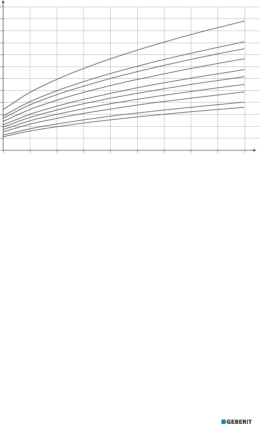
PRACTICAL USE ABSORPTION OF CHANGE IN LENGTH
131
G
G
G
G
G
G
G
G
G
G
L [m]
B
Change in length Δl [mm]
Figure172: Deflection leg length L
B
, copper pipes according to EN1057
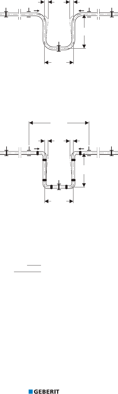
PRACTICAL USE ABSORPTION OF CHANGE IN LENGTH
132
Calculation of the deflection leg length for U-bends
The deflection leg length L
U
to be calculated is defined as follows:
ୠ,
³
ୠ,
³
/
X
*/ */)
)
)
/
X
³
a
Figure173: U-bend, made of bent pipe
F Anchor point
GL Guide bracket
L
U
Deflection leg length
Δl Change in length
ୠ,
³
/
X
/
X
³
a
ୠ,
³
G
*/ */) )
)
Figure174: U-bend, made with pressfittings
F Anchor point
GL Guide bracket
L
U
Deflection leg length
Δl Change in length
The deflection leg length L
U
is calculated using the following formula:
8୰¥G୰ୠ,
/
8
L
U
Deflection leg length [m]
d Outer pipe diameter [mm]
Δl Change in length [mm]
U Material constant

PRACTICAL USE ABSORPTION OF CHANGE IN LENGTH
133
Given:
• Material: Copper
• U = 29
• d=54mm
• Δl =29.1mm
Required:
• L
U
[m]
Solution:
8୰¥G୰ୠ,
/
8
P
PP
P
¥PPÃPP
/
8
ÃÃ
P
/
8
P
The deflection leg length L
U
can also be calculated in a simplified manner from the following graphics:
G
G
G
G
G
G
G
G
G
G
G
L [m]
U
Change in length Δl [mm]
Figure175: Deflection leg length L
U
, copper pipes according to DVGW GW 392:2015-04

PRACTICAL USE ABSORPTION OF CHANGE IN LENGTH
134
G
G
G
G
G
G
G
G
G
G
L [m]
U
Change in length Δl [mm]
Figure176: Deflection leg length L
U
, copper pipes according to EN 1057

PRACTICAL USE ABSORPTION OF CHANGE IN LENGTH
135
Calculation of the deflection leg length for Mapress CuNiFe
The thermal expansion of pipes depends on the material, among other things. Material-dependent parameters must be considered
when calculating the deflection leg length. The following table lists the parameters for Geberit Mapress CuNiFe.
Table73: Material-dependent Geberit Mapress CuNiFe parameters for calculating the deflection leg length
System pipe Material Thermal expansion coefficient α
[mm/(m•K)]
Material constant
C U
Geberit Mapress CuNiFe
2.1972.11
Copper-nickel forging
alloy
0.017 54 31
C for calculating the deflection leg length L
B
(change in direction, branch pipe)
U for calculating the deflection leg length L
U
(U-bend)
The calculation of the deflection leg length comprises the following steps:
• Calculation of the change in length Δl
• Calculation of the deflection leg length L
B
with a change in direction and branch pipe or calculation of the deflection leg length L
U
with U-bends.
Calculation of the change in length Δl
The change in length Δl is calculated using the following formula:
ୠ, /Ã̀Ãୠ7
Δl Change in length [mm]
L Pipe length [m]
ΔT Temperature differential (operating temperature - ambient temperature at time of installation) [K]
α Thermal expansion coefficient α [mm/(m • K)]
Given:
• Material: CuNiFe, material number 2.1972.11
• L=30m
• α=0.017mm/(m•K)
• ΔT=50K
Required:
• Change in length Δl [mm]
Solution:
ୠ, /Ã̀Ãୠ7
PÃPPÃ.
PP
PÃ.
Δl= 30 • 0.017 • 50 K
Δl = 25.5mm

PRACTICAL USE ABSORPTION OF CHANGE IN LENGTH
136
The change in length Δl can also be calculated in a simplified manner from the following tables.
Table74: Change in length Δl in mm for Geberit Mapress CuNiFe system pipe
L
[m]
Temperature differential ∆T
[K]
10 20 30 40 50 60 70 80 90 100
1 0.17 0.34 0.51 0.68 0.85 1.02 1.19 1.36 1.53 1.70
2 0.34 0.68 1.02 1.36 1.70 2.04 2.38 2.72 3.06 3.40
3 0.51 1.02 1.53 2.04 2.55 3.06 3.57 4.08 4.59 5.10
4 0.68 1.36 2.04 2.72 3.40 4.08 4.76 5.44 6.12 6.80
5 0.85 1.70 2.55 3.40 4.25 5.10 5.95 6.80 7.65 8.50
6 1.02 2.04 3.06 4.08 5.10 6.12 7.14 8.16 9.18 10.20
7 1.19 2.38 3.57 4.76 5.95 7.14 8.33 9.52 10.71 11.90
8 1.36 2.72 4.08 5.44 6.80 8.16 9.52 10.88 12.24 13.60
9 1.53 3.06 4.59 6.12 7.65 9.18 10.71 12.24 13.77 15.30
10 1.70 3.40 5.10 6.80 8.50 10.20 11.90 13.60 15.30 17.00
20 3.40 6.80 10.20 13.60 17.00 20.40 23.80 27.20 30.60 34.00
30 5.10 10.20 15.30 20.40 25.50 30.60 35.70 40.80 45.90 51.00
40 6.80 13.60 20.40 27.20 34.00 40.80 47.60 54.40 61.20 68.00
50 8.50 17.00 25.50 34.00 42.50 51.00 59.50 68.00 76.50 85
L Pipe length

PRACTICAL USE ABSORPTION OF CHANGE IN LENGTH
137
Calculation of the deflection leg length with a change in direction and branch pipe
The deflection leg length L
B
to be calculated is defined as follows with change in direction and for branch pipes:
ୠ,
/
%
*/
)
) */
Figure177: Expansion compensation with a change in direction
F Anchor point
GL Guide bracket
L
B
Deflection leg length
Δl Change in length
ୠ,
ୠ,
/
%
*/
*/
*/
Figure178: Expansion compensation with branch pipe
GL Guide bracket
L
B
Deflection leg length
Δl Change in length
The deflection leg length L
B
is calculated using the following formula:
/
%
&Ã¥GÃୠ,
L
B
Deflection leg length [m]
d Outer pipe diameter [mm]
∆l Change in length [mm]
C Material constant

PRACTICAL USE ABSORPTION OF CHANGE IN LENGTH
138
Given:
• Material: CuNiFe, material number 2.1972.11
• C = 54
• d=54mm
• Δl = 21mm
Required:
• L
B
[m]
Solution:
&୰¥G୰ୠ,
/
%
P
PP
P
¥PPÃPP
/
%
P
Ã¥Ã
/
%
P
The deflection leg length L
B
can also be calculated in a simplified manner from the following graphics:
G
G
G
G
G
G
G
G
G
L [m]
B
Change in length Δl [mm]
Figure179: Deflection leg length L
B
, Geberit Mapress CuNiFe

PRACTICAL USE ABSORPTION OF CHANGE IN LENGTH
139
Calculation of the deflection leg length for U-bends
The deflection leg length L
U
to be calculated is defined as follows:
ୠ,
³
ୠ,
³
/
X
*/ */)
)
)
/
X
³
a
Figure180: U-bend, made of bent pipe
F Anchor point
GL Guide bracket
L
U
Deflection leg length
Δl Change in length
ୠ,
³
/
X
/
X
³
a
ୠ,
³
G
*/ */) )
)
Figure181: U-bend, made with pressfittings
F Anchor point
GL Guide bracket
L
U
Deflection leg length
Δl Change in length
The deflection leg length L
U
is calculated using the following formula:
8୰¥G୰ୠ,
/
8
L
U
Deflection leg length [m]
d Outer pipe diameter [mm]
∆l Change in length [mm]
U Material constant
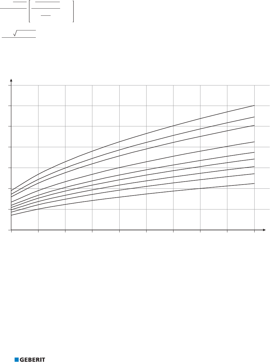
PRACTICAL USE ABSORPTION OF CHANGE IN LENGTH
140
Given:
• Material: CuNiFe, material number 2.1972.11
• U = 31
• d=54mm
• Δl = 21mm
Required:
• L
U
[m]
Solution:
8୰¥G୰ୠ,
/
8
P
PP
P
¥PPÃPP
/
8
ÃÃ
P
/
8
P
The deflection leg length L
U
can also be calculated in a simplified manner from the following graphics:
G
G
G
G
G
G
G
G
G
L [m]
U
Change in length Δl [mm]
Figure182: Deflection leg length L
U
, Geberit Mapress CuNiFe

PRACTICAL USE INSULATION OF PIPE SYSTEMS
141
2.5 INSULATION OF PIPE SYSTEMS
The insulation of pipe systems must fulfil various functions depending on the constructional situation:
• anticondensation insulation
• thermal insulation
• sound insulation
• absorption of low thermal expansion in pipes
There are a few basic rules to consider when insulating pipe systems:
• It is essential that the choice of insulation is designed to suit the area of use in order to ensure that insulation materials do not
damage the pipe material. The restrictions on use provided by the insulation material manufacturers must be observed.
• Insulation materials must be protected against moisture or consist of closed cells in order to avoid a reduction in the insulating
effect. Insulation does not replace corrosion protection.
• The installation and routing guidelines provided by the insulation material manufacturers must be observed.
• Insulation shells are not suitable for the absorption of low thermal expansion.
• The absorption of low thermal expansion in pipes is only possible in soft insulation.
• The insulation must be selected according to the respective area of application.
2.5.1 Insulation thicknesses for drinking water pipes according to BS 5422:2009
BS 5422:2009 contains reference values for insulation thicknesses for hot and cold water pipes. The calculation is made according to
BS EN ISO 12441 (which assumes still air).
Observe the insulation thicknesses specified in the corresponding tables of the standard or the specifications of other markets on the
following pages.
2.5.2 Insulation of potable water pipes
In drinking water pipes, the insulation fulfils the function of maintaining the drinking water quality, amongst other things. Cold-water
pipes must be insulated against heat and hot water pipes against heat loss.
Missing or unsuitable insulation has the following consequences:
• In cold-water pipes, the water quality can be affected by heat , e.g. through the formation of legionella. The temperature changes
also lead to condensation, which encourages corrosion.
• In hot water pipes and circulation lines, the water quality can be affected by heat loss, e.g. through the formation of legionella. Heat
loss also leads to increased energy consumption.
The design of the insulation and the insulation thicknesses depend on country-specific specifications and regulations.

PRACTICAL USE INSULATION OF PIPE SYSTEMS
142
2.5.3 Insulation thicknesses for cold-water pipes according to DIN 1988-200
The minimum insulation thicknesses for cold-water pipes can be taken from the following table for an insulation material with the
thermal conductivity λ=0.040W/(m•K). The values are designed for residential construction and apply for ambient temperatures of 5–
25°C and a maximum of 85% humidity.
Table75: Minimum insulation thicknesses for cold-water pipes (according to DIN 1988-200:2012-05)
Installation situation Ambient temperature Insulation thickness for the thermal
conductivity λ=0.040W/(m•K)
Surface-mounted pipes in unheated rooms (e.g.
basement)
≤20°C (only protection
against condensed water)
9mm
Pipes laid in pipe ducts, floor ducts and suspended
ceilings
≤25°C 13mm
Pipes laid, for example, in plant rooms or media
channels and ducts with heat loads
≥25°C
Insulation such as for hot water pipes,
installation situation 1–5
Floor pipes and individual supply pipes in prewall
installations
4mm
Floor pipes and individual supply pipes in floor
constructions (also in addition to non-circulating hot
water pipes)
1)
4mm
Floor pipes and individual supply pipes in a floor
construction in addition to heated circulating pipes
1)
13mm
λ Thermal conductivity of the insulation material at 10°C
Does not apply
1) The laying of cold-water pipes in connection with underfloor heating must fulfil the requirements of section 3.6 “Operating
temperature” of DIN 1988-200:2012-05. This means that 30 seconds after fully opening a point of use, the temperature of the cold
drinking water must not exceed 25°C during normal operation.
2.5.4 Insulation thicknesses for hot water pipes according to the Building Energy Act
The insulation thicknesses for heat distribution and hot water pipes and valves can be found in the following table. The specified
insulation thicknesses refer to the inner diameter of the pipes. In the case of insulation materials with other thermal conductivity values,
the insulation thicknesses must be converted.
Table76: Minimum insulating layer thicknesses for hot water pipes according to the German Building Energy Act (GEG)
Installation situation Insulation thickness for the thermal conductivity
λ=0.035W/(m·K)
1 Inner diameter ≤22mm 20mm
2 Inner diameter >22 and ≤35mm 30mm
3 Inner diameter >35and ≤100mm Same as the inner diameter
4 Inner diameter >100mm 100mm
5 Pipes and valves according to installation situations 1–4 in wall and
ceiling openings, at pipe junctions, at pipe connection points and in
central distribution systems
Half of the respective value for the installation
situations 1–4
6 Hot drinking water pipes that are neither included in the circulation
circuit nor equipped with pipe heating cable are, for example, floor
pipes and individual supply pipes with a water content ≤3l
No insulation requirements against heat emission
1)
λ Thermal conductivity of the insulation material at 40°C
1) Insulation is required for a concealed installation (e.g. 4mm as mechanical protection or– for heating and cooling water
installations with pipes made of non-alloy steel– as corrosion protection).
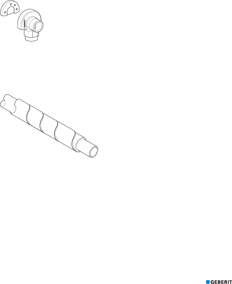
PRACTICAL USE INSULATION OF PIPE SYSTEMS
143
2.5.5 Sound insulation
Geberit supply systems do not produce any inherent noises with the correct system planning and installation. However, they emit
noises that come from appliances and valves. Pipes must therefore be equipped with structure-borne sound insulation that consistently
decouples the pipe system from the building structure, e.g. for feed-throughs or through the use of insulated pipe brackets. The
insulation must be implemented correctly and without any gaps. The thickness of the insulation is not of importance. Country-specific
requirements must be observed.
Sound insulation for tap connectors
In order to prevent the transmission of structure-borne sound, when fastening tap connectors they must be decoupled from the building
structure with a sound insulation set. In addition, it is necessary to prevent the connections getting dirty when fastening them, e.g. from
mortar.
Geberit connection bends can be protected with the following accessories:
Figure183: Geberit sound insulation set for single elbow tap connector 90°
Sound-insulating pipe jacketing
Pipe insulation devices such as insulation tape, insulation hoses, insulation shells with jacketing or terminations serve as sound-
insulating measures which decouple the piping system from the building structure.
The thickness of the insulation does not matter when it comes to decoupling from the building structure. Insulation must not be able to
absorb cement slurry, as this will re-establish contact between the pipe and the building.
Figure184: Geberit insulation tape

PRACTICAL USE RESISTANCE TO LIQUID AND GASEOUS MEDIA
144
2.6 RESISTANCE TO LIQUID AND GASEOUS MEDIA
In addition to their use for drinking water and heating water, Geberit supply systems can also be used for other liquid and gaseous
media. The medium itself may be modified due to the pipes or fittings. The suitability of the Geberit supply systems for different media is
therefore not only derived from the resistance of the pipes, but also depends on the medium's intended use.
The current usage overviews can be found in the online catalogue or in the printed catalogue.
If Geberit supply systems are intended for media other than those listed, the resistance of the pipe and sealing materials must be
checked and approved by Geberit.
The following are required for the approval:
• product and safety data sheets of the medium
• indication of the concentration
• exposure time, frequency and flow rate
• sample of the medium (only after consultation)
• planned operating temperature
• planned operating pressure
• maximum malfunction temperature
• ambient conditions (e.g. pipe layout through cleanroom, high humidity, permanent moisture, aggressive environment)
Resistance-related enquiries can be made online via the website of the Geberit sales companies.
The Geberit Industrial Application Tool is available at industryapplication.geberit.co.uk to assist in selecting a suitable piping system.

PRACTICAL USE CORROSION
145
2.7 CORROSION
Corrosion is the reaction of a metallic material to its environment, which causes a measurable change in the material and can lead to an
impairment in the function of a component or an entire system. Different types of corrosion can occur depending on the material and
application area. A distinction is generally made between external corrosion and internal corrosion. However, certain types of corrosion
can occur both internally and externally. Corresponding corrosion protection measures must be taken into account to avoid corrosion
occurring.
2.7.1 Corrosion behaviour of Geberit Mapress Stainless Steel
Resistance of stainless steel 1.4401 and 1.4521 to internal corrosion
Corrosion-resistant steels have a protective layer of chromium oxide. Due to this protective layer, the Geberit Mapress Stainless Steel
1.4401 and 1.4521 piping systems are corrosion-resistant to the following media:
• drinking water
• treated water (suitable for all water treatment techniques, such as ion exchange or reverse osmosis)
– softened (decarbonised) water
– fully desalinated water (deionised, demineralised, distilled and pure condensates)
– ultrapure water with a conductivity of ≥0.1μS/cm
• cooling water
Local corrosion symptoms (e.g. pitting or crevice corrosion) can only occur in combination with inadmissibly high chloride content levels
in media. Inadmissibly high chloride content levels occur, for example, if too much disinfectant containing chlorine is used when
disinfecting drinking water pipes. For this reason, the application duration and concentration of the disinfectant must be strictly
observed.
In order to avoid internal corrosion, the content of water-soluble chloride ions in drinking water, treated water and cooling water must
not exceed 250mg/l.
Resistance of stainless steel 1.4301 to internal corrosion
Corrosion-resistant steels have a protective layer of chromium oxide. Due to this protective layer, the Geberit Mapress Stainless Steel
1.4301 piping system is corrosion-resistant to the following media:
• treated water (suitable for all water treatment techniques, such as ion exchange or reverse osmosis)
– softened (decarbonised) water
– fully desalinated water (deionised, demineralised, distilled and pure condensates)
– ultrapure water with a conductivity of ≥0.1μS/cm
• cooling water
Local corrosion symptoms (e.g. pitting or crevice corrosion) can only occur in combination with inadmissibly high chloride content levels
in media.
In order to avoid internal corrosion, the content of water-soluble chloride ions in drinking water, treated water and cooling water must
not exceed 250mg/l.

PRACTICAL USE CORROSION
146
Resistance to external corrosion
Geberit Mapress Stainless Steel is resistant to environmental conditions in the corrosivity categories C1, C2 and C3 as well as Im1 and
Im3 without additional corrosion protection (see table below). In the case of ambient conditions that are assigned to a different
corrosivity category, corrosion protection measures are required, which must be defined in individual cases.
The following factors increase the risk of external corrosion:
• contact with building materials that promote corrosion (e.g. building materials containing chloride)
• installation in aggressive atmospheres (e.g. chlorine, nitric acid, hydrochloric acid)
• installations in which direct or indirect contact with electrical current (leakage current, amongst others) in combination with moisture
cannot be excluded
In cases such as these, suitable measures should be implemented to protect Geberit Mapress Stainless Steel.
Table77: Categories of atmospheric ambient conditions according to DIN EN ISO 12944-2
Corrosivity category Examples
C1 Unimportant Inside only: heated buildings with neutral atmospheres
C2 Low Rural areas, unheated buildings where condensation can occur, e.g.
warehouses, sports halls
C3 Moderate Urban and industrial atmospheres with moderate air pollution, coastal
areas with low salt pollution, production rooms with high humidity and
some air pollution (e.g. food production, laundries, breweries)
C4 Heavy Industrial areas, coastal areas with moderate salt pollution, chemical
plants, swimming pools
C5-I Very heavy (industry) Industrial areas with high humidity and aggressive atmospheres
C5-M Very heavy (sea) Coastal and offshore areas with high salt pollution, buildings with
almost constant condensation and with heavy air pollution
Im1 Fresh water Riverside buildings, hydroelectric power plants
Im2 Seawater or brackish water Port areas with steel structures, lock gates, jetties, offshore
installations
Im3 Ground Receptacles in the ground, steel sheet piles, steel pipes
Protection against external corrosion
Pipes must be treated with suitable corrosion protection to avoid external corrosion. Sealing tape or closed-cell insulation have been
proven to protect against external corrosion, as they prevent an accumulation of chlorides.
Corrosion protection must have the following properties:
• waterproof
• non-porous
• resistant to heat and ageing
• undamaged
The following rules must be observed when planning and designing the corrosion protection:
• A pressure test of the piping system must be carried out before applying the corrosion protection.
• The minimum protection against external corrosion is coating, priming or painting.
• Hoses or felt wrapping is not admissible, as felt retains absorbed moisture for prolonged periods and therefore promotes corrosion.
• The corrosion protection must not be damaged by pressing tools or other external influences.
Sanitary engineers and fitters are responsible for planning and implementing the corrosion protection.
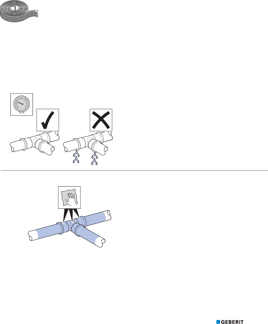
PRACTICAL USE CORROSION
147
Geberit sealing tape
Geberit sealing tape is characterised by the following advantages:
• reliable protection against external corrosion tested by Geberit
• self-adhesive
• easy installation
The processing temperature is between -10°C and +50°C.Geberit sealing tape is designed for operating temperatures of
-60to+100°C and therefore suitable for heating and cooling water installations. Geberit sealing tape is available in widths of 30mm
and 50mm.
Figure185: Geberit sealing tape
The following must be observed during installation:
• material overlap (pipe) at least 5cm
• material overlap (wrapping) at least 1 cm
• sealing tape with a width of 3 cm for an outer diameter up to d24mm
• sealing tape with a width of 5cm from an outer diameter of d25mm
• winding always under tension
Attaching the sealing tape
ü Leak test has been carried out.
1 Clean the surfaces of the connection points liberally.

PRACTICAL USE CORROSION
148
2 Wrap sealing tape around the pipe.
FP
FP
ð
Geberit insulation hose
The Geberit insulation hose made of closed-cell PE soft foam protects Geberit Mapress system pipes and fittings against chemical and
electro chemical influences from the outside.
The insulation hose is intended for gas installations and has an outer diameter of d15‒54mm.
Figure186: Geberit insulation hose with yellow protective foil
Corrosion behaviour of stainless steel in contact with other materials
Geberit Mapress Stainless Steel 1.4401, 1.4521 and 1.4301 can be combined with all materials in any order without affecting the
corrosion behaviour. The flow direction of the water must not be observed (no flow rules).
However, with a connection to zinc-plated steel pipes, bimetallic corrosion (galvanic corrosion) occurs on the zinc-plated steel pipes.
To avoid bimetallic corrosion, one or more of the following measures must be taken:
• installation of distance pieces (length L > 50mm of surface in contact with water)
• use of Geberit Mapress adapters made of gunmetal
• installation of a shut-off valve made of a non-ferrous heavy metal
Figure187: Geberit Mapress Copper adapter with male thread and plain end made of gunmetal
Discolouring caused by deposits of other corrosive products does not indicate any risk of corrosion.

PRACTICAL USE CORROSION
149
Corrosion risks during installation, processing and operation
When processing, installing and operating Geberit Mapress Stainless Steel systems with stainless steel 1.4401,1.4521 and 1.4301,
certain rules and general conditions must be observed in order to avoid corrosion. The most important scenarios and protective
measures are summarised below.
Scenario Type of corrosion Protective measure
Installation in a corrosive environment Contact with building materials that
promote corrosion, e.g. building
materials containing chlorine or
chloride
External corrosion
Pitting corrosion
• Sealing tape
• Closed-cell insulation
1)
Installation in aggressive atmospheres
(e.g. chlorine, nitric acid, hydrochloric
acid)
Installations in which direct or indirect
contact with electrical current (leakage
current, amongst others) in
combination with moisture cannot be
excluded
Combination of Geberit
Mapress Stainless Steel 1.4401,
1.4521 and 1.4301 with zinc-plated
steel pipes
Bimetallic corrosion
(galvanic corrosion)
2)
on the zinc-plated
steel pipe
• Installation of distance
pieces, surface in contact
with water must be longer
than 50 mm
• Use of Geberit Mapress
adapters made of
gunmetal
• Installation of a shut-off
valve made of a non-
ferrous heavy metal
Heating of stainless steel pipes Heating of steel pipes for bending Intercrystalline
corrosion
• No heating of system
pipes made of stainless
steel
• Cutting of system pipes
made of stainless steel to
length exclusively with the
pipe cutter, a pipe saw or
a pipe cutting machine
• No welding of system
pipes made of stainless
steel
Cutting to length with an abrasive cut-
off wheel (angle grinder) or with a
flame cutter
Welding of stainless steel pipes
Screwing joints made of stainless
steel
Use of sealing tape and sealing
materials made of
polytetrafluoroethylene containing
water-soluble chloride ions
Crevice corrosion • For stainless steel
screwing joints, only use
chloride-free sealant that
has been approved for
the respective application
Pressure test with water Pipe is not completed emptied after
the pressure test.
Pitting corrosion • The pipe must be
completed emptied after
the pressure test with
water.
Disinfection of drinking water pipes An excessive dose of the disinfectant
containing chlorine leads to an
inadmissibly high chloride content in
drinking water.
Pitting corrosion,
Crevice corrosion
• Strict adherence to the
duration of application
and the prescribed
concentration of the
disinfectant
Water quality An excessively high content of water-
soluble chloride ions
Internal corrosion • Strict adherence to the
maximum chloride
content of 250mg/l in
drinking water, treated
water and cooling water
and a conductivity ≤
2500µs/cm
1) The corrosion protection must be waterproof, non-porous, resistant to heat and ageing and free of damage.
2) Discolouring caused by deposits of other corrosive products does not indicate any risk of corrosion.

PRACTICAL USE CORROSION
150
2.7.2 Corrosion behaviour of Geberit Mapress Carbon Steel
Resistance to internal corrosion
Heating systems and other closed circuits
Geberit Mapress Carbon Steel is corrosion-resistant in closed heating systems and other closed systems. A system is considered
closed only if all components connected to the system (e.g. expansion tank, hoses, pumps and cooling and heating panels) form a
barrier against diffusion.
The country-specific requirements must be taken into account with regard to the quality of the heating or refrigerant fluid. It is desirable
to have a pH value of 8.2 -10.0 in closed heating systems. Only corrosion and antifreeze agents that have been tested and approved by
Geberit may be used.
The probability of corrosion increases when oxygen enters the system. If there is insufficient overpressure compared to the
atmosphere, oxygen can enter the circuit via the following components:
• open expansion tanks through which medium flows
• glands
• screw connections
• quick exhaust valve
The oxygen that enters the system when it is being filled and topped up with water does not pose a risk of corrosion as the quantities
involved are so small. The oxygen is bonded to iron oxide compounds through the reaction with the steel inner surface of the plant
system. In addition, the oxygen that is generated from the heated heating water escapes when the heating system is ventilated.
Concentrations of oxygen greater than 0.1 g/m
3
indicate an increased probability of corrosion.
Geberit Mapress Carbon Steel is not corrosion-resistant in respect to the condensate drains of oil fired condensing boilers. The
condensate in these systems has a pH value of 2.5–3.5 and may also contain sulphuric acid.
Resistance to external corrosion
Geberit Mapress Carbon Steel 1.0034, outside zinc-plated, bare or plastic-jacketed, is resistant to the environmental conditions of
corrosivity category C1 without additional corrosion protection.
Geberit Mapress Carbon Steel 1.0215, inside and outside zinc-plated, is resistant to the environmental conditions of corrosivity
category C1 without additional corrosion protection.
Geberit Mapress Carbon Steel must never be laid in areas with high moisture levels.
However, it is possible that unexpected moisture levels may occur. External corrosion may occur through longer exposure to
unintended corrosive media.
Unintended corrosive media includes, for example:
• rain penetration
• moisture in the masonry or screed
• condensation
• leaking water, spray or cleaning water
• extinguishing water
If there is a risk of unintended corrosive media, suitable measures must be taken to protect Geberit Mapress Carbon Steel.

PRACTICAL USE CORROSION
151
Table78: Categories of atmospheric ambient conditions according to DIN EN ISO 12944-2
Corrosivity category Examples
C1 Unimportant Inside only: heated buildings with neutral atmospheres
C2
Low Rural areas, unheated buildings where condensation can occur, e.g.
warehouses, sports halls
C3
Moderate Urban and industrial atmosphere with moderate air pollution, coastal
areas with low salt pollution, production rooms with high humidity and
some air pollution (e.g. food production, laundries, breweries)
C4
Heavy Industrial areas, coastal areas with moderate salt pollution, chemical
plants, swimming pools
C5-I Very heavy (industry) Industrial areas with high humidity and an aggressive atmosphere
C5-M
Very heavy (sea) Coastal and offshore areas with high salt pollution, buildings with
almost constant condensation and with heavy air pollution
Im1 Fresh water Riverside buildings, hydroelectric power plants
Im2
Seawater or brackish water Port areas with steel structures, lock gates, jetties, offshore
installations
Im3 Ground Receptacles in the ground, steel sheet piles, steel pipes
Protection against external corrosion
Protection against external corrosion must meet the following requirements:
• waterproof
• non-porous
• forms a barrier against diffusion
• resistant to heat and ageing
• undamaged
To prevent external corrosion, the following must be observed:
• Before applying the corrosion protection, a pressure test and a leak test of the piping system must be carried out.
• Closed-cell sealing materials such as sealing tape or insulation hoses have proven to be effective in protecting against external
corrosion. Only dry insulation may be used.
• Geberit Mapress Carbon Steel must never be installed in permanently damp rooms or environments. Lay pipes outside rooms with
high humidity levels.
• To protect against unforeseen moisture, the use ofGeberit Mapress Carbon Steel (plastic-jacketed) with sealing tape is
recommended.
• It is important to prevent direct contact between unprotected carbon steel pipes and fire protection boards in feed-throughs passing
through fire sections. A corrosion protection coating or anticorrosion tape must be applied to the pipe at section joints.
• In the case of concealed or underfloor installation, Geberit Mapress Carbon Steel system pipes and pressfittings must be protected
using a suitable form of corrosion protection. Geberit strongly recommends the use of Geberit Mapress Carbon Steel (plastic-
jacketed) in these areas.
• When laying pipes on concrete floors, a sealing foil must be laid between the concrete floor and the steel pipe in addition to the
pipe cladding.
• Vertical radiator connections out of the screed must be avoided, as permanent protection from moisture cannot be guaranteed.
Geberit recommends a radiator connection from the back out of the wall, for example, with a radiator connection box.
• The processing guidelines of the corrosion protection manufacturers must always be observed.
The insulation used must be dry.
Sanitary engineers and fitters are responsible for planning and implementing the corrosion protection.

PRACTICAL USE CORROSION
152
Geberit sealing tape
Geberit sealing tape is characterised by the following advantages:
• reliable protection against external corrosion tested by Geberit
• self-adhesive
• easy installation
The processing temperature is between -10°C and +50°C.Geberit sealing tape is designed for operating temperatures of
-60to+100°C and therefore suitable for heating and cooling water installations. Geberit sealing tape is available in widths of 30mm
and 50mm.
Figure188: Geberit sealing tape
The following must be observed during installation:
• material overlap (pipe) at least 5cm
• material overlap (wrapping) at least 1 cm
• sealing tape with a width of 3 cm for an outer diameter up to d24mm
• sealing tape with a width of 5cm from an outer diameter of d25mm
• winding always under tension
Closed-cell insulation hoses
Closed-cell insulation hoses have proven to protect against external corrosion as they prevent the concentration of chlorides. The cut
surfaces and joints of the insulation must be carefully bonded, no pores must be created and the insulated pipe must be longitudinally
watertight.
Closed-cell insulation is not adequate corrosion protection for cooling water installations. Coolant water pipes must be protected against
corrosion according to AGI worksheet Q151 “Corrosion protection under insulation”.
Figure189: Corrosion protection with closed-cell insulation hoses

PRACTICAL USE CORROSION
153
Corrosion risks during installation, processing and operation
During the processing, installation and operation of Geberit Mapress Carbon Steel systems, certain rules and general conditions must
be observed in order to avoid corrosion. The most important scenarios and protective measures are summarised below.
Table79: Corrosion risks
Scenario Type of corrosion Protective measure
Transport in an open means of
transport
Pipes are exposed to moisture External corrosion • Use only closed or well-
covered means of
transport
• Do not cover pipes with
plastic foil to prevent
condensation
Pipes show signs of corrosion during
storage
Pipes are permanently exposed to
moisture
External corrosion • Do not cover pipes with
plastic foil to prevent
condensation
• Do not store pipes directly
on the floor
• Avoid contact with other
metals in a humid
environment
Unexpected moisture load in rooms Corrosive media can unintentionally
occur, for example, in the following
cases:
• embedded precipitation,
especially in new buildings
• moisture in the floor construction
and masonry
• defective water supply line
• condensation
• leaking and splash water
• use of cleaning agents and
disinfectants
• extinguishing water
External corrosion • Use of the jacketed pipe
with additional sealing
tape
• Sealing material must be
water-resistant and
diffusion-tight
• The cut surfaces and
joints of the insulation
hoses must be carefully
bonded
• All positions where
Mapress Carbon Steel
can come into contact
with moisture must be
wrapped
Use in cooling water installations Closed-cell insulation alone does not
provide corrosion protection
External corrosion • Execute corrosion
protection for cooling
water installations
according to AGI
worksheet Q151EU and/
or BS 5970
Laying on concrete floors Moisture from the concrete floor External corrosion • In addition to the pipe
cladding, lay sealing foil
between the concrete
floor and steel pipe
Radiator connections vertically out of
the screed
Contact with cleaning water or
aggressive cleaning agents
External corrosion • If possible, install the
radiator connection from
the back out of the wall,
for example, with a
radiator connection box
Improper use, for example, for
draining condensate from oil fired
condensing boilers
Condensate with a pH value of 2.5–
3.5 and sulphurous acids
Internal corrosion • Consult the usage
overviews or a specialist
adviser prior to the
installation
Signs of corrosion despite use in a
closed system
The system has components that
allow oxygen diffusion, for example,
glands, screw connections, quick
exhaust valves or expansion tanks
with a permeable membrane
Internal corrosion • Connect only diffusion-
tight components
• Connect components that
can be ventilated
• Produce sufficient
overpressure relative to
the atmosphere

PRACTICAL USE CORROSION
154
Scenario Type of corrosion Protective measure
Pressure test No complete emptying of the pipe
after the pressure test
Internal corrosion • Empty the pipe
completely after the
pressure test
• Perform the pressure test
with compressed air
Water quality Increased corrosion probability due to
• Concentrations of oxygen greater
than 0.1g/m
3
• pH value is too low (lower than
8.2 in circulating water, lower
than 6.0 in filling water)
Internal corrosion • Observe the country-
specific guidelines for
heating water.
• See the “Geberit piping
systems for treated water”
technical information for
the admissible oxygen
concentration, pH values,
TOC, etc.
• Use only water additives
tested and approved by
Geberit
2 / 2
Geberit Mapress Carbon Steel system pipes in solar thermal systems
Geberit Mapress Carbon Steel system pipes, outside zinc-plated, are an economical alternative to Geberit Mapress Stainless Steel
system pipes and Geberit Mapress Copper system pipes, especially in the case of large pipe dimensions. However, when using Geberit
Mapress Carbon Steel system pipes, outside zinc-plated, the following rules must be observed. See the “Geberit piping systems for
solar thermal systems” technical information for further information.
Solar thermal drainback system
Solar thermal systems are generally designed as closed circuits. Exceptions are solar systems with a solar thermal drainback system.
These solar systems are operated without antifreeze agents in the thermal medium, since they automatically empty when there is a
danger of frost. This procedure introduces oxygen into the solar system. Oxygen can cause internal corrosion on Geberit
Mapress Carbon Steel system pipes, outside zinc-plated.
Geberit Mapress Carbon Steel system pipes, outside zinc-plated, must therefore not be used for solar thermal systems with a solar
thermal drainback system.
Laying pipes in outdoor areas
Laying pipes outdoors is subject to increased requirements for the resistance of the piping system to external corrosion.
The zinc layer of the Geberit Mapress Carbon Steel system pipes, outside zinc-plated, even when combined with correctly implemented
thermal insulation, does not provide sufficient corrosion protection for laying pipes outdoors.
Geberit Mapress Carbon Steel system pipes, outside zinc-plated, therefore have to be protected with an additional corrosion protection
coating. Alternatively, Geberit Mapress Stainless Steel system pipes can be laid in the outdoor area of the solar system and Geberit
Mapress Carbon Steel system pipes, outside zinc-plated, can be laid inside.
Connection of the solar collector to the piping system
Temperatures up to 220 °C can occur for short periods in the connection area of the solar collector. As a result of these high
temperatures, the first one to two metres of the piping system must be implemented with a corrugated pipe made of stainless steel and
the solar collector must be connected to the corrugated pipe made of stainless steel with a metallic clamping joint.

PRACTICAL USE CORROSION
155
2.7.3 Corrosion behaviour of Geberit Mapress Copper
Resistance to internal corrosion
Geberit Mapress Copper is corrosion-resistant to the following media:
• Drinking water with the following features:
– pH value>7.4
– 7.4>pH value >7.0 and TOC
1)
<1.5 g/m
– salt content which does not exceed the limited values of the Drinking Water Ordinance
• Heating water and cooling water in open and closed systems
• Treated water according to the Technical Information “Geberit piping systems for treated water” (suitable for all water treatment
processes, such as ion exchange or reverse osmosis)
– softened (decarbonised) water
– fully desalinated water (deionised, demineralised, distilled and pure condensates)
– ultrapure water with a conductivity of ≥0.1μS/cm
1)
TOC (Total Organic Carbon): total organic carbon content
Resistance to external corrosion
Geberit Mapress Copper is resistant to the ambient conditions of corrosivity categories C1, C2 and C3 without additional corrosion
protection (see table below). In the case of ambient conditions that are assigned to a different corrosivity category, corrosion protection
measures are required, which must be defined in individual cases.
The following factors increase the risk of external corrosion:
• contact with building materials that promote corrosion (e.g. building materials containing sulphides, nitrites and ammonium)
• installation in aggressive atmospheres (e.g. chlorine, nitric acid, hydrochloric acid)
In cases such as these, suitable measures should be implemented to protect Geberit Mapress Copper.
Table80: Categories of atmospheric ambient conditions according to DIN EN ISO 12944-2
Corrosivity category Examples
C1 Unimportant Inside only: heated buildings with neutral atmospheres
C2 Low
Rural areas, unheated buildings where condensation can occur, e.g.
warehouses, sports halls
C3 Moderate
Urban and industrial atmosphere with moderate air pollution, coastal
areas with low salt pollution, production rooms with high humidity and
some air pollution (e.g. food production, laundries, breweries)
C4 Heavy
Industrial areas, coastal areas with moderate salt pollution, chemical
plants, swimming pools
C5-I Very heavy (industry) Industrial areas with high humidity and an aggressive atmosphere
C5-M Very heavy (sea)
Coastal and offshore areas with high salt pollution, buildings with
almost constant condensation and with heavy air pollution
Im1 Fresh water Riverside buildings, hydroelectric power plants
Im2 Seawater or brackish water
Port areas with steel structures, lock gates, jetties, offshore
installations
Im3 Ground Receptacles in the ground, steel sheet piles, steel pipes
Corrosion behaviour of Mapress Copper in contact with other materials
Geberit Mapress Copper can be combined with all the materials in the following systems without affecting the corrosion behaviour:
• atmospherically closed water heating systems
• water circuits without risk of internal corrosion
However, when combined with zinc-plated steel pipes, bimetallic corrosion (galvanic corrosion) can occur on the zinc-plated steel pipes
if the flow rule is not observed. To avoid bimetallic corrosion, copper must always be installed in the direction of water flow downstream
of components made of zinc-plated steel.

PRACTICAL USE CORROSION
156
Stress corrosion cracking in copper-zinc alloys (brass)
Stresses can occur in components in water distribution systems according to EN 12502-1:2004 (DIN EN 12502-1:2005-03), which can
cause stress corrosion cracking in combination with corrosive media.
When working with brass threaded joints, it is important to make sure not to apply too much stress, such as by overtightening them.
Corrosion risks during installation, processing and operation
During the processing, installation and operation of Geberit Mapress Copper systems, certain rules and general conditions must be
observed in order to avoid corrosion. The most important scenarios and protective measures are summarised below.
Scenario Type of corrosion Protective measure
Installation in a corrosive environment Contact with building materials that
promote corrosion, e.g. building
materials containing sulphides, nitrites
and ammonium
External corrosion
Pitting corrosion
• Sealing tape
• Closed-cell insulation
1)
Installation in aggressive atmospheres
(e.g. chlorine, nitric acid, hydrochloric
acid)
Combination of Mapress Copper with
zinc-plated steel pipes
Bimetallic corrosion
(galvanic corrosion)
2)
on the zinc-plated
steel pipe
• Compliance with the flow
rule: Always install copper
in the direction of the
water flow downstream
of zinc-plated steel pipe
Threaded joints are incorrectly sealed Excessive tightening Stress corrosion
cracking
• Do not overtighten the
threaded joint
Disinfection of drinking water pipes An excessive dose of the disinfectant
containing chlorine leads to an
inadmissibly high chloride content in
drinking water
Pitting corrosion
Crevice corrosion
• Strict adherence to the
duration of application
and prescribed
concentration of the
disinfectant
Water quality An excessively high content of water-
soluble chloride ions
pH value>7.4
7.4>pH value>7.0 and TOC<1.5g/
m
Internal corrosion • Strict adherence to the
maximum chloride
content of 250mg/l in
drinking water, treated
water and cooling water
and a conductivity ≤
2500µs/cm
1) The corrosion protection must be waterproof, non-porous, resistant to heat and ageing and free of damage.
2) Discolouring caused by deposits of other corrosive products does not indicate any risk of corrosion.

PRACTICAL USE CORROSION
157
2.7.4 Corrosion behaviour of Geberit Mapress CuNiFe
Resistance to internal corrosion
Corrosion resistance of copper-nickel alloys
Copper-nickel alloys are among the most corrosion-resistant copper product materials.
They are resistant to:
• moisture
• seawater
• non-oxidising acids
• alkalis
• salt solutions
• organic acids
• dry gases (oxygen, chlorine, hydrogen chloride, hydrogen fluoride, sulphur dioxide and carbon dioxide)
Copper-nickel alloys with 10% nickel (Ni) have good resistance to seawater. This also applies to hot seawater and flow speeds of up to
6m/s.
Resistance of Geberit Mapress CuNiFe to seawater
Geberit Mapress CuNiFe system pipes and fittings made of CuNi10Fe1.6Mn have excellent corrosion resistance, especially to
seawater. This high corrosion resistance is due to a natural, thin protective coating that quickly forms upon contact with clean seawater
and makes the system pipe corrosion-resistant.
This complex protective coating is mainly made up of copper(I) oxide and is improved by additional nickel and iron. The protective
coating forms within a few days but needs up to three months to form fully. The initial contact (exposure) is decisive for the long-term
behaviour of copper-nickel, i.e. the pipes must be continually exposed to a flow of clean seawater so that the protective coating can
form.
Seawater resistance is a given for:
• cold seawater
• hot seawater
• average flow speeds of up to 6m/s
If the flow speed for a given geometry is too high, the protective coating may be damaged from the effect of the shearing stress
produced by the seawater, and this can lead to impact erosion.
According to DIN EN 85004-2, the flow speed should be between 1 m/s and 3 m/s depending on the diameter.
The iron content of the copper-nickel alloy considerably improves the adhesive strength of the corrosion protection layer and, therefore,
resistance to erosive corrosion, particularly in seawater and other aggressive types of water, such as brackish water. Sand abrasion is
not easy to quantify, as many factors play a role, such as the sand content of the water, the grain size or the flow profile. The piping
systems must be equipped with suitable screening devices for the removal of sand and other residues which could damage the
protective foil.
Effect of contaminated seawater
If contaminated seawater containing sulphides comes into contact with the inside of the pipe as the first service water, the sulphides
can impair the formation of the protective surface film. The sulphides produce a black surface film containing copper oxide and
sulphide. This surface film is not as protective as the protective coating that forms under clean seawater and makes the pipeline
susceptible to pitting corrosion.
If an intact copper(I) oxide layer has already formed under the influence of clean seawater, no damage to the protective coating is to be
expected from periodic exposure to contaminated water.
Risk of corrosion due to heavy chlorination
Copper-nickel alloys demonstrate good resistance to pitting corrosion. Excessive chlorination of the medium affects the corrosion
resistance.

PRACTICAL USE CORROSION
158
Resistance to chlorine
Geberit Mapress CuNiFe system pipes made of CuNi10Fe1.6Mn are resistant to chlorine in the following concentrations:
Proportion of free chlorine
[ppm]
Continuous chlorination 1
Shock chlorination 5
1)
1) According to information from EUCARO
Resistance to external corrosion
Due to the seawater resistance of copper-nickel alloys, no external corrosion occurs in Geberit Mapress CuNiFe system pipes when
used in salty or humid environments. Protection against external corrosion is therefore not necessary.
Corrosion behaviour of Geberit Mapress CuNiFe in contact with other materials
Geberit Mapress CuNiFe is compatible with other copper alloys. In combination with other materials such as aluminium or steel, it can
cause bimetallic corrosion, which can be prevented through galvanic isolation of the various materials, for example, with a plastic plate.

PRACTICAL USE PIPE LAYING
159
2.8 PIPE LAYING
2.8.1 Basic laying process
The following sequence applies for the laying of Geberit pressing systems:
1. Fasten the pipes in sliding brackets.
2. Connect the pipes and pressfittings.
3. Press the pipes and pressfittings.
Pressed pipes must be kept tension-free during the installation (e.g. with pipe brackets).

PRACTICAL USE PIPE LAYING
160
2.8.2 Storey distribution
Individual supply pipe system
With an individual supply pipe system, each point of use is connected to a separate feed pipe from the floor manifold.
This installation method is selected if these are short pipe lengths between the manifold and the points of use.
Figure190: Individual supply pipe system
Advantages:
• minimal planning and calculation work required
• small pipe cross-sections
• low water content per pipe
• minimised pressure losses
• individual connection for higher water requirements
• quick and easy pipe installation
• clear direction of flow
Disadvantages:
• risk of stagnation if all points of use are not used regularly
• points of use must be used regularly
• greater space requirements for pipes and floor manifold
• longer pipe lengths
Block pipe system
Matching sanitary connections such as a washbasin and WC exit a common floor manifold as several series connections. The
connections are either single or double connections.
Figure191: Block pipe system
Advantages:
• shorter pipe lengths
• low space requirements for floor manifold
• minimal planning and calculation work required
• rarely used points of use can be looped through frequently used points of use
• clear direction of flow
Disadvantages:
• higher pressure loss
• for larger diameters, it may be more difficult to maintain the draw-off times

PRACTICAL USE PIPE LAYING
161
Series-connected pipe system
The pipe is routed from one point of use to the next with double connections. Points of use are combined in groups and supplied by a
common pipe.
Figure192: Series-connected pipe system
Advantages:
• minimal planning and calculation work required
• shorter pipe lengths
• low space requirements for floor manifold
• lower stagnation volume due to fast water replacement
• good drinking water hygiene when the last point of use is regularly used
• clear direction of flow
Disadvantages:
• higher pressure loss
• there must be a larger point of use at beginning of the series
• for larger diameters, it may be more difficult to maintain the draw-off times
Circular pipe system
In a circular pipe system, the points of use are connected to each other via double connections, as in a series-connected pipe system.
The pipe leads back to the manifold from the last point of use. The potable water flows from two sides while water is drawn off and
therefore flows through all connections.
Figure193: Circular pipe system
Advantages:
• lower pressure loss enables higher water draw-off and considerably more points of use with the same size pipe cross-section
• various points of use can be connected at greater distances from the floor manifolds or riser pipes
• low space requirements for floor manifold
Disadvantages:
• direction of flow and flow through all sections not clear
• complex calculation
• for larger diameters, it may be more difficult to maintain the draw-off times

PRACTICAL USE PIPE LAYING
162
Combined pipe system
The individual supply pipe, series-connected pipe and circular pipe variants can be combined.
Figure194: Combined pipe system
Installation examples of a high-standard apartment:
• Individual supply pipe for a shower. If possible, connect at the start of the floor manifold.
• Series-connected pipe for a washbasin and WC
• Circular pipe in systems with increased drinking water hygiene requirements
Advantages:
• Pipe layout can be adapted to the respective requirements
• Low pressure losses
• Minimised risk of stagnation
• Optimum water replacement at draw-off points which are not often used
Disadvantage:
• More complex calculation
2.8.3 Installation on uncovered concrete floors
In addition to country-specific regulations, the following rules must be observed for installations on uncovered concrete floors:
• In order to facilitate the installation of impact sound insulation, pipes laid on the uncovered concrete floor should be arranged and,
if possible, routed next to each other.
• It is important to check whether the pipes on the uncovered concrete floor need to be defined in accordance with the national
regulations.
• In order to minimise heat transfer when cold and hot water pipes are laid next to each other, a minimum distance of 10cm should
be maintained between the pipes.
• Compensation measures are necessary above the pipes to create a flat surface to accommodate the insulating layer or at least a
sound insulation layer. The necessary construction height must be included in plans.
Figure195: Pipe laying on uncovered concrete floors
1 Top layer
2 Cast plaster floor
3 Film
4 Impact sound insulation
5 Thermal insulation
6 System pipe
7 Pipe insulation
8 Cavity filling (e.g. Perlite or Meabit)
9 Uncovered concrete floor

PRACTICAL USE PIPE FIXATION
163
2.9 PIPE FIXATION
2.9.1 Fastening of pipes with anchor and guide brackets
Pipe fastenings support the pipe and direct the temperature-related changes in length in the required direction. Distinctions are made
between pipe fastenings based on anchor points and guide brackets.
An anchor point is a rigid pipe installation which directs the pipe expansion to an expansion compensator.
A guide bracket is an axially movable pipe bracket.
Guide brackets must be set so that they do not become unwanted anchor points during operation.
2.9.2 Pipe bracket spacing for drinking water installations
Surface-mounted Geberit Mapress Stainless Steel system pipes are fastened with pipe brackets. Geberit pipe brackets, insulated, can
be used to prevent the transmission of structure-borne sound.
5$ 5$ 5$
The following table lists the maximum pipe bracket spacing recommended by Geberit as well as the distances for Geberit
Mapress Stainless Steel according to EN 806-4:2010.
Table81: Maximum pipe bracket spacing and load per pipe bracket for Geberit Mapress Stainless Steel for drinking water installations
d
[mm]
RA
1)
As recommended by
Geberit
[m]
F
[N]
RA
According to EN 806-4
F
[N]
12 1.5 5.3 1.0 3.5
15 1.5 7.3 1.0 4.8
18 1.5 9.4 1.2 7.5
22 2.5 23.2 1.8 16.7
28 2.5 33.0 1.8 23.8
35 3.5 72.2 2.4 49.5
42 3.5 95.1 2.4 65.2
54 3.5 140.6 2.7 108.4
76.1 5.0 389.8 3.0 233.9
88.9 5.0 500.8 3.0 300.5
108 5.0 690.4 3.0 414.3
RA Pipe bracket spacing
F Load per pipe bracket, pipe filled with water at 10°C
1) Different pipe bracket spacing applies for sprinkler, extinguishing and gas installations.

PRACTICAL USE PIPE FIXATION
164
2.9.3 Pipe bracket spacing for sprinkler and extinguishing water systems
The following table includes the maximum pipe bracket spacing according to VdS CEA 4001:2021-01, which is also recommended by
Geberit.
Table82: Maximum pipe bracket spacing RA and load per pipe bracket, sprinkler and extinguishing water systems
d
[mm]
RA
[m]
F
2)
[N]
According to VdS CEA 4001:2021-01
1)
22 2.0 18.6
28 2.0 26.4
35 2.0 41.3
42 2.0 54.4
54 2.0 80.3
76.1 2.0 156.0
88.9 2.0 200.4
108 2.0 276.2
F Load per pipe bracket
1) and Geberit recommendation
2) Pipe, filled with water, 10°C
2.9.4 Thickness of the pipe fixation for guide brackets
Pipe brackets are fastened to the wall or ceiling with threaded rods or threaded pipes. The required thickness of the pipe bracket
fastenings must be selected depending on the ceiling or wall distance.
Table83: Required thickness of the pipe bracket fastenings of guide brackets on ceilings and walls
d
[mm]
Distance between pipe brackets
[cm]
Ceiling distance Wall distance
≤10 11–20 21–30 31–40 41–60 ≤10 11–20
12 M8 M8 M8 M10 M10 M8 M10
15 M8 M8 M8 M10 M10 M8 M10
18 M8 M8 M10 M10 M10 M8 M10
22 M8 M10 1/2" 1/2" 1/2" M10 M10
28 M10 M10 1/2" 1/2" 1/2" M10 M10
35 M10 M10 1/2" 1/2" 1/2" M10 1/2"
42 1/2" 1/2" 1/2" 1/2" 1/2" 1/2" 1/2"
54 1/2" 1/2" 1/2" 1/2" 1/2" 1/2" 1/2"
66.7 1/2" 1/2" 1/2" 1/2" 1/2" 1/2" 1/2"
76.1 1/2" 1/2" 1/2" 1/2" 1/2" 1/2" 1/2"
88.9 1/2" 1/2" 1/2" 1/2" 1/2" 1/2" 1/2"
108 1/2" 1/2" 1/2" 1/2" 1/2" 1/2" 1/2"

PRACTICAL USE PIPE FIXATION
165
2.9.5 Installation dimensions of Geberit mounting plates
Geberit mounting plates are used to fasten Geberit connections.
Geberit mounting plate Number of possible
connections
DS
[cm]
AD1
[cm]
Straight Offset
1 – –
$'
$'
2 12 10
$'
$'
2 15.3 7.3
AD Connecting distance
Different installation dimensions and depths are achieved with concealed and exposed installation of Geberit mounting plates.
Figure196: Installation dimension for concealed installation with a Geberit mounting plate, offset
Figure197: Installation dimension for exposed installation with a Geberit mounting plate, offset
Figure198: Installation dimension for exposed installation with a Geberit mounting plate, straight

PRACTICAL USE PIPE FIXATION
166
2.9.6 Minimum distances for pressing
In order to avoid damage to already pressed connections or to permit the correct pressing of pipes and fittings, the following distances
must be maintained between 2 pressing operations and for wall and ceiling feed-throughs:
G
'
ZX
(
$
PLQ
/
PLQ
(
%
PLQ
&
PLQ
G
d Outer pipe diameter
D
WU
Outer fitting bead diameter
L
min
Minimum length of the system pipe
A
min
Minimum distance between 2 fittings
B
min
Minimum distance from the fitting to the wall
C
min
Minimum depth of the system pipe
E Insertion distance
d
[mm]
D
WU
[mm]
L
min
[cm]
A
min
[cm]
B
min
[cm]
C
min
[cm]
E
[cm]
12 20 4.4 1.0 3.5 5.2 1.7
15 20 5.0 1.0 3.5 5.2 2.0
18 26 5.0 1.0 3.5 5.5 2.0
22 32 5.2 1.0 3.5 5.5 2.1
28 38 5.6 1.0 3.5 5.6 2.3
35 45 6.2 1.0 3.5 5.8 2.6
42 54 8.0 2.0 3.5 6.1 3.0
54 66 9.0 2.0 3.5 6.5 3.5
66.7 84 12.0 2.0 3.0 7.0 5.0
76.1 95 12.6
1)
/ 13.6
2)
2.0
1)
/ 3.0
2)
7.5 12.8 5.3
88.9 110 14.0
1)
/ 15.0
2)
2.0
1)
/ 3.0
2)
7.5 13.5 6.0
108 133 17.0
1)
/ 18.0
2)
2.0
1)
/ 3.0
2)
7.5 15.0 7.5
1) The dimensions apply for pressing operations with Geberit pressing attachments with compatibility [1], [2], [2XL] and [3].
2) The dimensions apply for pressing operations with Geberit pressing attachments with compatibility HCP.
Pressing attachments with compatibility HCP may only be used for Geberit Mapress Stainless Steel, Mapress Carbon Steel
and Mapress CuNiFe. They are not suitable for pressing copper.

PRACTICAL USE PIPE FIXATION
167
2.9.7 Space requirements when pressing with Geberit Mapress pressing jaws
The following minimum distances must be observed for pressing in cramped conditions, for example, in ducts or pipework, in order to
be able to fit the pressing tool correctly.
Table84: Space requirements for pressing jaws with compatibility [1] and [2], maximum dimension
Compatibility/pressing jaw
Mounting on a smooth wall
$
&
Mounting in a corner
$
&
%
Mounting in a duct
&
'
$
d
[mm]
A
[cm]
C
[cm]
A
[cm]
B
[cm]
C
[cm]
A
[cm]
C
[cm]
D
[cm]
[1] 12 1.8 4.6 2.4 3.7 5.5 2.4 5.5 12.9
15 2.1 5.0 2.5 3.7 5.5 2.5 5.5 12.9
18 2.3 5.1 2.5 4.0 5.5 2.5 5.5 13.5
22 2.4 6.1 2.7 4.4 6.3 2.7 6.3 15.1
28 2.7 6.5 3.2 4.6 6.9 3.2 6.9 16.1
35 3.1 8.1 3.6 5.6 8.2 3.6 8.2 19.4
[1] 12 2.2 5.5 2.6 4.4 6.1 2.6 6.1 14.9
15 2.4 5.6 2.5 4.8 6.0 2.5 6.0 15.6
18 2.6 5.9 2.9 4.5 6.6 2.9 6.6 15.6
22 2.6 6.4 3.1 4.8 6.8 3.1 6.8 16.4
28 3.0 7.4 3.4 5.4 7.5 3.4 7.5 18.3
35 3.5 8.4 3.9 6.0 8.5 3.9 8.5 20.5
[2] 12 2.2 4.8 2.8 4.0 5.5 2.8 5.5 13.5
15 2.4 5.0 2.9 4.1 6.2 2.9 6.2 14.4
18 2.6 5.0 2.6 3.9 6.0 2.6 6.0 13.8
22 2.9 6.2 3.2 4.9 6.9 3.2 6.9 16.7
28 3.0 6.5 3.0 4.4 6.9 3.0 6.9 15.7
35 3.4 7.5 3.7 5.5 7.6 3.7 7.6 18.6
[2] 12 2.2 5.4 2.5 4.5 6.2 2.5 6.2 15.2
15 2.4 5.5 2.6 4.5 6.2 2.6 6.2 15.2
18 2.6 5.9 2.9 4.5 6.5 2.9 6.5 15.5
22 2.9 6.3 3.3 4.8 6.8 3.3 6.8 16.4
28 3.0 7.0 3.6 5.0 7.5 3.6 7.5 17.5
35 3.4 8.2 4.0 5.90 8.4 4.0 8.4 20.2

PRACTICAL USE PIPE FIXATION
168
2.9.8 Space requirements when pressing with Geberit Mapress pressing collars
The following minimum distances must be provided for pressing with Geberit Mapress pressing collars in order to be able to position the
pressing tool correctly:
Table85: Space requirements when pressing with pressing collars with compatibility [2]/[3] and [2XL]/[3]
Compatibility/pressing collar
Mounting on a smooth wall
$
&
Mounting in a corner
$
&
%
Mounting in a duct
$
&
'
d
[mm]
A
[cm]
C
[cm]
A
[cm]
B
[cm]
C
[cm]
A
[cm]
C
[cm]
D
[cm]
[2]/[3] 35 7.5 11.5 7.5 7.5 11.5 7.5 11.5 26.5
42 7.5 11.5 7.5 7.5 11.5 7.5 11.5 26.5
54 8.5 12.0 8.5 8.5 12.0 8.5 12.0 29.0
66.7 9.5 14.0 9.5 9.5 14.0 9.5 14.0 33.0
[2XL]/[3] 76.1 11.5 15.5 11.0 11.5 15.5 11.0 15.5 38.0
88.9 12.5 16.5 12.0 12.5 16.5 12.0 16.5 41.0
108 14.5 18.5 14.0 14.5 18.5 14.0 18.5 47.0
2.9.9 Space requirements when pressing with Geberit pressing tool HCPS
Pipe diameter
Complete premounting
$
(
% & '
Mounting of the individual system sections
$
% & )
d
[mm]
A
[cm]
B
[cm]
C
[cm]
D
[cm]
E
[cm]
A
[cm]
B
[cm]
C
[cm]
F
[cm]
76.1 11.0 20.0 22.0 22.0 30.0 11.0 16.0 16.0 60
88.9 12.0 20.0 22.0 22.0 32.0 12.0 16.0 18.0 60
108 13.0 20.0 23.0 23.0 34.0 13.0 16.0 20.0 60

PRACTICAL USE PRESSING TOOLS
169
2.10 PRESSING TOOLS
A pressing tool is defined as a pressing tool with a pressing attachment inserted. Pressing jaws, adapter jaws and pressing collars are
designated as pressing attachments.
Geberit pressing tools and pressing attachments are specifically designed for pressing Geberit system pipes and fittings. Using Geberit
pressing tools or the pressing tools from other manufacturers recommended by Geberit together with the original Geberit pressing
attachments is a prerequisite for the additional Geberit warranty.
2.10.1 Pressing tools and pressing attachments
The suitable pressing attachment is inserted into the pressing tool for pressing the pipe and fitting.
The following pressing attachments are used depending on the pipe diameter:
• pressing jaws for pipe diameters ≤ d35
• pressing collars with adapter jaws for pipe diameters ≥ d35
The pressing contour of the Geberit pressing jaws and pressing collars has been designed to suit the geometry of the Geberit
pressfittings.
2.10.2 Maintenance and service plans for Geberit Mapress pressing jaws
The maintenance regulations for zinc-plated Geberit Mapress pressing jaws are different from those without zinc plating. The zinc-
plated pressing jaws with compatibility [1] and [2] are service-free, i.e. they do not require a service by an authorised repair shop if they
are used as intended. The black pressing jaws with compatibility [1], [2] and [3] are subject to a service and require an annual service
by an authorised repair shop.
All pressing jaws must be regularly maintained. Pressing jaws that are not maintained, or are not professionally maintained, can cause
accidents and injuries.
The intervals listed in the table as well as the maintenance and service work must be followed.
Table86: Maintenance plan for service-free Geberit Mapress pressing jaws with compatibility [1] and [2]
Interval Work
User maintenance
Regularly (before use, at the
start of the working day)
▶ Check the Geberit pressing jaw for external safety-relevant defects
and damage (e.g. incipient cracks, rust spots) and replace if
defective.
▶ Remove deposits in the pressing contour.
▶ Spray the pressing contour with BRUNOX® Turbo-Spray® or
similar and clean with a cloth.
▶ Examine whether the jaw levers can move easily. If necessary,
move the adapter jaw levers several times until they are able to
move easily.
Every six months ▶ Check that the Geberit pressing jaw is fully closed and has
sufficient press capacity using the Geberit PowerTest. If defects
are detected during the check, the pressing jaw, pressing tool and
PowerTest must be sent to an authorised repair shop.
The service-free Geberit Mapress pressing jaws and the service-free adapter jaw 203A do not get a service sticker. The test is
documented through the Geberit PowerTest.

PRACTICAL USE PRESSING TOOLS
170
Table87: Maintenance and service plan for Geberit Mapress pressing jaws with compatibility [1], [2] and [3] that are subject to a service
Interval Work
User maintenance
Regularly (before use, at the
start of the working day)
▶ Check the Geberit pressing jaw for external safety-relevant defects
and damage (e.g. incipient cracks, rust spots) and replace if
defective.
▶ Clean and lubricate the pressing jaws, see the user manual.
▶ Check screw connections if present and retighten if necessary.
▶ Examine whether the jaw levers can move easily. If necessary,
spray the jaw joints with BRUNOX® Turbo-Spray® and move them
around.
▶ Wipe off any excess lubricant.
▶ Spray the pressing contour and joints with BRUNOX® Turbo-
Spray®. After a short application time, remove any dirt and
deposits with a cloth.
▶ Spray the entire pressing jaw with BRUNOX® Turbo-Spray® or
similar.
Service by a
repair shop
Annually ▶ Arrange for an authorised repair shop to check the state of wear.
A service sticker on the pressing tool, pressing jaw, adapter jaw and pressing collar indicates the date when the next service is
due.
Arrange for the pressing tool (type ACO pressing tools with a battery charger) to be sent for a service together with the
pressing jaws, adapter jaws and pressing collars in the transport case.
The addresses of authorised repair shops can be requested from the Geberit sales companies.

PRACTICAL USE PRESSING TOOLS
171
2.10.3 Using the Geberit PowerTest
Check the pressing jaw for cracks and take the necessary measures.
1 Clean the contour of the pressing jaw.
2 Prepare the PowerTest.
Remove the pressing indicator before a pressing operation with the PowerTest.
*HEHULW0DSUHVV

PRACTICAL USE PRESSING TOOLS
172
3 Stick the PowerTest to the pressing jaw.
4 Perform the pressing operation with the PowerTest.
5 Remove and evaluate the PowerTest.

PRACTICAL USE PRESSING TOOLS
173
2.10.4 Maintenance plan for the service-free adapter jaw 203 A
The Geberit Mapress adapter jaw ZB203A must be regularly maintained by the user. It is not necessary for this adapter jaw to be sent
to an authorised repair shop.
Table88: Maintenance plan for the service-free Geberit adapter jaw ZB 203A with compatibility [2]
Interval Maintenance
User maintenance
ZB203A [2] Regularly (before use, at the
start of the working day)
▶ Check the Geberit adapter jaw ZB203A for external safety-relevant
defects and damage (e.g. incipient cracks, rust spots) and replace
if defective.
▶ Spray the entire adapter jaw with BRUNOX®Turbo-Spray® and
clean with a cloth.
▶ Examine whether the jaw levers can move easily. If necessary,
move the jaw levers several times until they are able to move
easily.
2.10.5 Maintenance and service plans for Geberit Mapress pressing collars and adapter jaws
Geberit Mapress pressing collars and adapter jaws must be regularly maintained and tested by an authorised repair shop. An exception
is the Geberit Mapress ZB 203A adapter jaw, which is maintained by the user. The ZB203A is not sent to a repair shop.
Pressing collars and adapter jaws that are not maintained, or are not professionally maintained, can cause accidents and injuries.
The intervals listed in the table as well as the maintenance and service work must be followed.
A service sticker on the pressing tool, pressing jaw, adapter jaw and pressing collar indicates the date when the next service is
due.
Arrange for the pressing tool (type ACO pressing tools with a battery charger) to be sent for a service together with the
pressing jaws, adapter jaws and pressing collars in the transport case.
The addresses of authorised repair shops can be requested from the Geberit sales companies.

PRACTICAL USE PRESSING TOOLS
174
Table89: Maintenance and service plan for Geberit Mapress pressing collars and adapter jaws [2], [2XL] and [3]
Interval Work
User maintenance
All pressing collars and
all adapter jaws with
compatibility [2], [2XL]
and [3]
Regularly (before use, at the
start of the working day)
▶ Check the pressing collar and adapter jaw for external safety-
relevant defects and damage (e.g. incipient cracks, rust spots) and
replace if defective or arrange for the defects to be repaired by an
authorised repair shop.
▶ Check screw connections and retighten if necessary.
▶ Examine whether the jaw levers can move easily. If necessary,
spray the jaw joints with BRUNOX®Turbo-Spray® or similar and
move them around. Wipe off any excess lubricant.
▶ Spray the pressing contour with BRUNOX®Turbo-Spray® or
similar, leave for a short application time and remove dirt and
deposits with a cloth.
▶ Lubricate joints and interlocks with BRUNOX®Turbo-Spray® or
similar and move them around until they can move easily. Wipe off
any excess lubricant.
▶ Spray BRUNOX®Turbo-Spray® or similar between the sliding
segments and shells and move them around until they can move
easily. Wipe off any excess lubricant.
▶ Lightly spray the entire adapter jaw and pressing collar with
BRUNOX®Turbo-Spray® or similar.
Pressing collars [3]
ZB [3]
▶ In addition to the above-mentioned maintenance work, clean the
electrical contacts.
Service by a repair shop
Pressing collars [2XL]
ZB201
ZB301
Pressing collars [2] to
12-2011
ZB221
ZB222
Pressing collars [3]
ZB321
ZB322
ZB323
ZB324
Annually ▶ Arrange for an authorised repair shop to check the state of wear.
Pressing collars [2] from
01-2012
ZB203
ZB303
3,000 pressing operations,
after one year at the latest
ZB Adapter jaw

PRACTICAL USE PRESSING TOOLS
175
2.10.6 Maintenance and service plans for pressing tools
Maintenance and service plans for pressing tools with a mains connection
Pressing tools and pressing attachments that are not maintained, or are not professionally maintained, can cause serious accidents.
The maintenance and service intervals as well as maintenance and service work described below must be followed.
Table90: Maintenance and service plan for pressing tools with a mains connection and compatibility [2], [3]
Pressing tool In the range
[MM/YY]
Interval Work
User maintenance
All Regularly (before use, at the start of the
working day)
▶ Check the pressing tool and mains
cable or rechargeable battery for
defects and damage that could affect
safety.
▶ Clean and lubricate the pressing tool
(see the operation manual).
All Every six months ▶ Have a qualified electrician or an
authorised repair shop carry out an
inspection and take measurements to
establish any defects or damage that
could affect safety.
▶ Country-specific regulations can
necessitate specific tests and
maintenance work.
EFP2 [2] 01/05‒06/16 Every six months or after 2,500 pressing
operations
▶ Top up with gearbox grease (art. no.
90010).
Service by a repair shop
EFP2 [2]
ECO201 [2]
01/05‒06/16
02/01‒03/11
Annually ▶ Have an authorised repair shop check
the pressing force and the state of
wear.
EFP202 [2] 04/11‒04/16 After 40,000 pressing operations or after
2 years at the latest in accordance with
the information on the service sticker
ECO202 [2] 04/11‒04/16 After 40,000 pressing operations (interval
is indicated by the red and green LEDs
flashing alternately) or after 2 years at the
latest in accordance with the information
on the service sticker
ECO203 [2]
ECO301 [3]
04/16‒until now
01/05‒03/19
If the red and green LEDs flash alternately
or after 2 years at the latest in
accordance with the information on the
service sticker
EFP203 [2] 04/16‒until now After 2 years in accordance with the
information on the service sticker
Does not apply
A service sticker on the pressing tool, pressing jaw, adapter jaw and pressing collar indicates the date when the next service is
due.
Arrange for the pressing tool (type ACO pressing tools with a battery charger) to be sent for a service together with the
pressing jaws, adapter jaws and pressing collars in the transport case.
The addresses of authorised repair shops can be requested from the Geberit sales companies.

PRACTICAL USE PRESSING TOOLS
176
Maintenance and service plan for pressing tools with a rechargeable battery
Pressing tools and pressing attachments that are not maintained, or are not professionally maintained, can cause serious accidents.
The maintenance and service intervals as well as maintenance and service work described below must be followed.
Table91: Maintenance plan for pressing tools with a rechargeable battery and compatibility [1], [2], [2XL]
Pressing tool In the range
[MM/YY]
Interval Work
User maintenance
All Regularly (before use, at the start
of the working day)
▶ Check the pressing tool and mains
cable or rechargeable battery for
defects and damage that could
affect safety.
▶ Clean and lubricate the pressing
tool (see the operation manual).
All Every six months ▶ Have a qualified electrician or an
authorised repair shop carry out an
inspection and take measurements
to establish any defects or damage
that could affect safety.
▶ Country-specific regulations can
necessitate specific tests and
maintenance work.
Service by a repair shop
AFP101 [1]
ACO201 [2]
07/06‒04/12
04/11‒04/16
Annually ▶ Have an authorised repair shop
check the pressing force and the
state of wear.
ACO102 [1]
ACO202 [2]
04/12‒04/18
04/11‒04/16
After 40,000 pressing operations
(interval is indicated by the red and
green LEDs flashing alternately) or
after 2 years at the latest in
accordance with the information on
the service sticker
ACO103plus [1]
ACO203 [2]
ACO203plus [2]
ACO203XL [2]/[2XL]
ACO203XLplus [2]/[2XL]
04/18‒until now
04/16‒04/18
04/18‒until now
01/05‒03/19
04/18‒until now
If the red and green LEDs flash
alternately or after 2 years at the
latest in accordance with the
information on the service sticker
Does not apply
A service sticker on the pressing tool, pressing jaw, adapter jaw and pressing collar indicates the date when the next service is
due.
Arrange for the pressing tool (type ACO pressing tools with a battery charger) to be sent for a service together with the
pressing jaws, adapter jaws and pressing collars in the transport case.
The addresses of authorised repair shops can be requested from the Geberit sales companies.

PRACTICAL USE PIPEWORK
177
2.11 PIPEWORK
2.11.1 Processing temperature
The Geberit Mapress piping systems can be processed at ambient temperatures of -20°C to 60°C.
Battery-operated pressing tools can be used in temperatures ranging from -10°C to 50°C.
2.11.2 Cutting of bare system pipes to length
The following are suitable for cutting Geberit Mapress system pipes to length:
• Geberit Mapress pipe cutterR
• fine-toothed hand mitre saw
• pipe cutter with electric motor
• electric saw (e.g. Rothenberger Pipecut, Orbitalum RA41 Plus)
Figure199: Suitable cutting tool
The use of abrasive cut-off wheels and cutting pipes to length using a welding torch are inadmissible due to the uncontrolled thermal
effect on the cut surfaces and the resulting risk of corrosion.
Figure200: Inadmissible cutting tool

PRACTICAL USE PIPEWORK
178
The following must be observed when cutting pipes to length:
• The inside of the pipe must be free of foreign bodies such as plastic foils, inserted protection plugs, etc.
• Only use a cutting tool suitable for the material.
• The cut surfaces must be smooth to prevent damage to the seal ring in the fitting.
• The pipes must be cut professionally, completely and at a right angle. It is not admissible to break off a pipe that has not yet been
completely cut to length.
2.11.3 Cutting of system pipes with a plastic jacket to length
Electric saws are particularly suitable for cutting Geberit Mapress system pipes with a plastic jacket to length. When cutting with a pipe
cutter, the plastic jacket can become compressed or raised.
Damage to the plastic jacket when using a pipe cutter depends on the following factors:
• pipe dimension
• pipe length
• temperature
• construction of the pipe cutter
When using a pipe cutter, Geberit therefore recommends removing the plastic jacket in the area of the counterpressure rollers of the
pipe cutter before cutting the pipe to length.
The Geberit Mapress stripping tool is normally used to strip pipes. The stripping device is set at the factory to the correct dimension of
the insertion distance.
Alternatively, the plastic jacket can be marked with the pipe cutter and carefully slit with a universal cutter. It is important to ensure that
the pipe surface in the subsequent seal ring area is not damaged and that the correct insertion distance is maintained. In the case of
systems requiring approval, the correct insertion distance must also be marked with a marker pen on the plastic jacket.
(
Figure201: Stripping with the Geberit Mapress stripping tool.

PRACTICAL USE PIPEWORK
179
2.11.4 Deburring of system pipes
Depending on the pipe dimension, Geberit Mapress system pipes must be deburred with a manual deburrer, such as the Geberit
Mapress pipe deburrer or the Geberit Mapress RE 1 electric pipe deburrer.
The Geberit Mapress pipe deburrer is available in the following designs:
• for d12–35mm, art. no.90357
• for d12–54mm, art. no.90363
The Geberit Mapress RE1 electric pipe deburrer is compatible with the pipe dimensions d15–108mm, art. no. 691.000.P3.3.
G²
G²
Figure202: Deburring with a manual deburrer or with an electric pipe deburrer
The following must be observed when deburring and chamfering the cut edges:
• The deburring tool must be free of chips.
• The lowest rotational frequency must be set when deburring with the electric pipe cutter.
• The cut edges must be carefully deburred on the inside and outside.
• The inside of the pipe must be free of foreign bodies such as residual plastic foil or a protection plug.
• The pipe ends must be completely free of chips to prevent damage to the seal in the fitting.
• The pipe ends must be checked to ensure that they are intact after deburring.

PRACTICAL USE PIPEWORK
180
2.11.5 Bending system pipes
The following rules apply for bending GeberitMapress system pipes:
• Pipes are only suitable for cold bending. The heating process changes the structure of the material, which can lead to
intercrystalline corrosion.
• Pipes can only be bent with standard bending tools.
• From a pipe dimension of d54 mm, special tools are required for bending, which are offered by specialist manufacturers.
• The regulations of the bending tool manufacturer must also be observed for the suitability of the bending tool and determination of
the bending radius.
Smallest bending radius for GeberitMapress system pipes:
• bending by hand: r ≥ 5 • d
• bending with a bending tool: r ≥ 3.5 • d
2.11.6 Bending of copper pipes
The following rules apply for the bending of copper pipes:
• Pipes are only suitable for cold bending. The heating process changes the structure of the material, which can lead to
intercrystalline corrosion.
• Pipes can only be bent with standard bending tools.
• A special tool, which is offered by specialist manufacturers, is required for bending pipes with a dimension larger than d54.
• The regulations of the bending tool manufacturer must also be observed for the suitability of the bending tool and determination of
the bending radius.
Table92: Smallest bending radius for copper pipes with a strength of R250 and R290 according to DVGW GW 392:2015-04 and EN 1057:2006+A1:2010 (based
on the neutral axis)
d
[mm]
Smallest bending radius
r [mm]
R250(half-hard) R290(hard)
12 45 45
15 55 55
18 70 70
22 77
28 114
No definition in the specified standards
2.11.7 Calibration of copper pipes
The pipe ends of soft copper pipes must always be calibrated.
To do this, the calibration ring and calibration mandrel are pushed one after the other onto or into the pipe end.

PRACTICAL USE PIPEWORK
181
2.11.8 Determination of the insertion distance
In order to create a secure pressed joint, the insertion distance must be determined and marked on the pipe before the pipe and fitting
are connected together.
(
Figure203: Marking of the insertion distance
The strength of the connection is only achieved by maintaining the specified insertion distance.
The marking of the insertion distance must be visible on the pipe after inserting the pipe into the pressfitting and after pressing
it.
On fittings with a plain end, the insertion distance must be marked on the plain end.
Figure204: Marking of the insertion distance on fittings with a plain end
Pressfitttngs with a plain end, such as bends with plain ends, may only be shortened up to the minimum admissible leg length.

PRACTICAL USE PRESSING PREPARATIONS
182
2.12 PRESSING PREPARATIONS
To avoid any impurities, only pressfittings with protection plugs should be used.
The following must be observed prior to the pressing:
• The protection plug must only be removed immediately before the pressfitting is pushed onto the pipe.
• The seal ring must be correctly positioned.
• When replacing the seal ring, it must not be damaged, for example, by using pointed or sharp-edged objects.
• The seal ring must be free of foreign bodies.
• No lubricant must be applied to the pressfitting.

PRACTICAL USE PRESSING PREPARATIONS
183
• The fitting must be pushed onto the pipe by turning it slightly in the axial direction up to the marked insertion distance.
• To prevent damage to the seal ring, the pipe must not be prised into the pressfitting.
(
(
Figure205: Marking on the pipe to check the correct insertion distance
Prising the pipe into the pressfitting can damage the seal ring and cause the pressed joint to leak.
In order to maintain the specified insertion distance, the pipes must be fixed accordingly. For pipe dimensions d54–108mm, the Geberit
Mapress mounting aid can be used to fix the pipes.
Figure206: Geberit Mapress mounting aid MH1

PRACTICAL USE CREATING A PRESSED JOINT
184
2.13 CREATING A PRESSED JOINT
For information on the pressing of Geberit Mapress system pipes and pressfittings, see the pressing tool operation manuals as
well as the Geberit Mapress pressing jaw and pressing collar user manuals.
The Geberit Mapress system components must not be processed when ambient temperatures are below -20°C. Pressing
tools with a rechargeable battery can only be used in temperatures ranging from -10 to +50°C.
Before a pressed joint is created, the pipe or prefabricated components must be aligned and the screwing joints sealed. During the
pressing operation, the guide for the pressing jaw or pressing collar must be positioned on the fitting groove.
Figure207: Positioning of the Geberit Mapress pressing jaw and pressing collar

PRACTICAL USE CREATING A PRESSED JOINT
185
After the pressing operation, the pressing indicator is removed from the pressfitting.
Figure208: Removing the pressing indicator
You can identify that a pressing operation has been carried out correctly as follows:
• the mark indicating the insertion distance is visible
• the pressing indicator is removed
Figure209: Correct pressing operation

PRACTICAL USE TRACE HEATER
186
2.14 TRACE HEATER
A trace heater can be used as a temperature maintenance or frost protection system.
The trace heater is installed directly on the Geberit system pipe. In order to ensure an adequate and uniform transfer of heat from the
trace heater, the installation regulations must be followed in accordance with the manufacturer information.
Technical measures must be taken to prevent an inadmissible pressure increase during the warm-up phase.
Figure210: Principle of a hot water pipe with heating cable
Only self-regulating heating cables may be used. The temperature must not exceed the maximum admissible temperature for
the respective system.

PRACTICAL USE TRANSFER OF HEAT
187
2.15 TRANSFER OF HEAT
Transfer of heat refers to the transportation of energy in the form of heat across at least one thermodynamic boundary. The heat is
transferred in the direction of the environment with the lower temperatures.
Heat emission is when the thermal energy is transferred from inside to outside, and thermal absorption is when the thermal energy is
transferred in the opposite direction.
Pipes can be used for heat emission (underfloor heating, heating ceilings, heating walls, etc.) and also for thermal absorption (cooling
water systems, geothermal heat storage, etc.).
2.15.1 Calculation of the heat emission
The heat emission
R
is calculated using the following formula:
4
5
7
L
²7
D
ÃN
U
Ã
R
Heat flow for 1 m pipe [W/m]
k
r
Heat transfer coefficient [W/(m·K)]
T
i
Water temperature in the pipe
T
a
Room temperature
In the first step, the heat transfer coefficient k
r
is calculated. The heat transfer coefficient k
r
can be calculated using a general or
simplified formula.
2.15.2 Geberit Mapress Stainless Steel
General calculation of the heat transfer coefficient
The general method of calculating the heat transfer coefficient is used when the pipe transfers the heat through the atmosphere. The
general calculation of the heat transfer coefficient k
r
is based on the following assumptions:
• surface-mounted pipeline
• stationary air
The heat transfer coefficient k
r
is calculated using the following calculation formula:
N
U
̀
L
୰G
L
୰͊
̀
D
୰G
D
ÃOQ
G
D
G
L
α
i
Heat transfer coefficient, inside [W/(m
2
•K)]
α
a
Heat transfer coefficient, outside [W/(m
2
•K)]
d
a
Outer diameter [mm]
d
i
Inner diameter [mm]
λ Thermal conductivity [W/(m•K)]
Applicable for Geberit Mapress Stainless Steel system pipes 1.4401:
• α
i
=6000W/(m
2
•K)
• α
a
=8.1W/(m
2
•K)
• λ=15W/(m•K)

PRACTICAL USE TRANSFER OF HEAT
188
Simplified calculation of the heat transfer coefficient
The simplified calculation of the heat transfer coefficient is used when the pipe only transfers the heat to another component or a liquid.
With this method, the heat transfer coefficient is calculated using the following formula without taking into account the radiant
proportion:
N
U
̀
D
୰G
D
k
r
Heat transfer coefficient
α
a
Heat transfer coefficient, outside [W/(m
2
•K)]
d
a
Outer diameter [mm]
The following applies for Geberit system pipes:
• α
a
=8.1W/(m
2
•K)
Tabulated determination of the heat emission
The heat emission can also be calculated in a simplified manner from the following table. The values of the heat flow
R
are based on
the general calculation of the heat transfer coefficients k
r
.
Table93: Heat flow
R
in watts per metre [W/m], GeberitMapress Stainless Steel system pipes 1.4401
d
[mm]
s
[mm]
Temperature differential ΔT
[K]
10 20 30 40 50 60 70 80 90 100
12 1 3.0 6.1 9.2 12.2 15.3 18.4 21.4 24.4 27.6 30.5
15 1 3.2 7.4 12.2 17.4 22.9 28.7 34.8 41.2 47.7 54.5
18 1 3.7 8.6 14.1 20.1 26.5 33.2 40.3 47.6 55.2 63.1
22 1.2 4.3 10.0 16.5 23.5 31.0 38.9 47.2 55.8 64.7 73.9
28 1.2 5.2 12.2 20.0 28.5 37.5 47.1 57.1 67.5 78.3 89.5
35 1.5 6.2 14.5 23.8 34.0 44.8 56.2 68.2 80.7 93.6 107.0
42 1.5 7.2 16.8 27.6 39.3 51.8 65.0 78.8 93.3 108.2 123.8
54 1.5 8.9 20.8 34.2 48.7 64.2 80.6 97.8 115.7 134.3 153.5
76.1 2 11.6 26.9 44.2 63.0 83.1 104.3 126.5 149.7 173.9 198.9
88.9 2 13.1 30.5 50.0 71.3 94.0 118.1 143.2 169.5 196.9 225.3
108 2 15.4 35.6 58.4 83.3 109.8 137.9 167.4 198.1 230.1 263.3

PRACTICAL USE TRANSFER OF HEAT
189
Graphical determination of the heat emission
The heat emission can also be calculated in a simplified manner from the following graphics. The values of the heat flow
R
are based
on the general calculation of the heat transfer coefficients k
r
.
G
G
G
G
G
G
G
G
G
G
G
Temperature differential Δ [K]
Heat flow [W/m]
T
R
Figure211: Heat emission for Geberit Mapress Stainless Steel 1.4401

PRACTICAL USE TRANSFER OF HEAT
190
2.15.3 Geberit Mapress Carbon Steel
General calculation of the heat transfer coefficient
The general method of calculating the heat transfer coefficient is used when the pipe transfers the heat through the atmosphere. The
general calculation of the heat transfer coefficient k
r
is based on the following assumptions:
• surface-mounted pipeline
• stationary air
The heat transfer coefficient k
r
is calculated using the following general formula:
N
U
̀
L
୰G
L
୰͊
̀
D
୰G
D
ÃOQ
G
D
G
L
α
i
Heat transfer coefficient, inside [W/(m
2
•K)]
α
a
Heat transfer coefficient, outside [W/(m
2
•K)]
d
a
Outer diameter [mm]
d
i
Inner diameter [mm]
λ Thermal conductivity [W/(m•K)]
For Geberit Mapress Carbon Steel, the following values are taken for the calculation:
• α
i
= 23.2 W/(m
2
•K)
• α
a
= 8.1 W/(m
2
•K)
• λ = 60 W/(m•K)
Simplified calculation of the heat transfer coefficient
The simplified calculation of the heat transfer coefficient is used when the pipe only transfers the heat to another component or a liquid.
With this method, the heat transfer coefficient is calculated using the following formula without taking into account the radiant
proportion:
N
U
̀
D
୰G
D
k
r
Heat transfer coefficient
α
a
Heat transfer coefficient, outside [W/(m
2
•K)]
d
a
Outer diameter [mm]
The following applies for Geberit system pipes:
• α
a
=8.1W/(m
2
•K)

PRACTICAL USE TRANSFER OF HEAT
191
Tabulated determination of the heat emission
The heat emission can also be calculated in a simplified manner from the following table. The values of the heat flow
R
are based on
the general calculation of the heat transfer coefficients k
r
.
Table94: Heat flow
R
in watts per metre [W/m], Geberit Mapress Carbon Steel system pipes
d
[mm]
s
[mm]
Temperature differential ΔT
[K]
10 20 30 40 50 60 70 80 90 100
12 1.2 3.9 8.9 14.5 20.6 27.2 34.2 41.6 49.4 57.6 66.2
15 1.2 4.7 10.7 17.5 24.9 32.8 41.2 50.2 59.6 69.5 79.9
18 1.2 5.5 12.5 20.4 29.0 38.2 48.1 58.5 69.5 81.1 93.2
22 1.5 6.3 14.3 23.3 33.1 43.6 54.8 66.8 79.3 92.6 106.5
28 1.5 7.8 17.6 28.7 40.7 53.7 67.5 82.2 97.7 114.0 131.2
35 1.5 9.5 21.5 34.9 49.5 65.3 82.1 100.0 118.9 138.8 159.8
42 1.5 11.2 25.2 40.8 58.0 76.4 96.1 117.0 139.2 162.5 187.1
54 1.5 14.4 32.3 52.5 74.5 98.2 123.6 150.5 178.9 209.0 240.6
66.7 1.5 16.8 37.8 61.2 86.8 114.5 144.0 175.4 208.7 243.8 280.9
76.1 2 19.2 43.1 69.8 99.0 130.5 164.2 200.0 237.9 278.0 320.2
88.9 2 22.0 49.3 79.9 113.3 149.3 178.8 228.7 272.2 318.1 366.5
108 2 26.1 58.4 94.6 134.1 176.7 222.2 270.8 322.2 376.7 434.1
Graphical determination of the heat emission
The heat emission can also be calculated in a simplified manner from the following graphics. The values of the heat flow
R
are based
on the general calculation of the heat transfer coefficients k
r
.
G
G
G
G
G
G
G
G
G
G
G
Temperature differential ΔT [K]
Heat flow [W/m]
R
Figure212: Heat emission for Geberit Mapress Carbon Steel system pipes

PRACTICAL USE TRANSFER OF HEAT
192
2.15.4 Geberit Mapress Copper
General calculation of the heat transfer coefficient
The general calculation of the heat transfer coefficient kr is based on the following assumptions:
• surface-mounted
• stationary air
The heat transfer coefficient k
r
is calculated in the general calculation using the following formula:
N
U
̀
L
୰G
L
୰͊
̀
D
୰G
D
ÃOQ
G
D
G
L
α
i
Heat transfer coefficient, inside [W/(m
2
•K)]
α
a
Heat transfer coefficient, outside [W/(m
2
•K)]
d
a
Outer diameter [mm]
d
i
Inner diameter [mm]
λ Thermal conductivity [W/(m•K)]
For Geberit Mapress Copper, the following values are taken for the calculation:
• α
i
=6000W/(m
2
•K)
• α
a
=8.1W/(m
2
•K)
• λ=305W/(m•K)
Simplified calculation of the heat transfer coefficient
The simplified calculation of the heat transfer coefficient is used when the pipe only transfers the heat to another component or a liquid.
With this method, the heat transfer coefficient is calculated using the following formula without taking into account the radiant
proportion:
N
U
̀
D
୰G
D
k
r
Heat transfer coefficient
α
a
Heat transfer coefficient, outside [W/(m
2
•K)]
d
a
Outer diameter [mm]

PRACTICAL USE TRANSFER OF HEAT
193
Tabulated determination of the heat emission
The heat emission can also be calculated in a simplified manner from the following table. The values of the heat flow
R
are based on
the general calculation of the heat transfer coefficients k
r
.
Table95: Heat flow
R
in watts per metre [W/m], copper pipes
d
[mm]
Temperature differential ΔT
[K]
10 20 30 40 50 60 70 80 90 100
12 2.5 5.9 9.9 14.1 18.7 23.5 28.4 33.6 39.0 44.4
15 3.0 7.0 11.7 16.7 22.1 27.8 33.7 39.8 46.1 52.6
18 3.4 8.1 13.4 19.2 25.4 31.9 38.7 45.7 53.0 60.4
22 3.9 9.4 15.6 22.3 29.6 37.1 45.0 53.2 61.7 70.4
28 4.7 11.3 18.7 26.8 35.5 44.6 54.1 64.0 74.1 84.6
35 5.6 13.3 22.2 31.8 42.1 52.9 64.2 75.8 87.9 100.3
42 6.4 15.3 25.5 36.6 48.4 60.8 73.8 87.2 101.1 115.4
54 7.8 18.6 30.9 44.4 58.7 73.8 89.6 105.9 122.8 140.1
76.1 10.1 24.2 40.3 57.9 76.6 96.3 116.9 138.3 160.4 183.1
88.9 11.4 27.3 45.5 65.3 86.5 108.8 132.1 156.3 181.3 207.0
108 13.3 31.8 53.0 76.1 100.9 126.9 154.1 182.4 211.6 241.6
Graphical determination of the heat emission
The heat emission can also be calculated in a simplified manner from the following graphics. The values of the heat flow
R
are based
on the general calculation of the heat transfer coefficients k
r
.
G
G
G
G
G
G
G
G
G
G
G
Temperature differential ΔT [K]
Heat flow [W/m]
R
Figure213: Heat emissions for copper pipes

PRACTICAL USE TRANSFER OF HEAT
194
2.15.5 Geberit Mapress CuNiFe
General calculation of the heat transfer coefficient
The general calculation of the heat transfer coefficient k
r
is based on the following assumptions:
• surface-mounted pipeline
• stationary air
The heat transfer coefficient k
r
is calculated using the following general formula:
N
U
̀
L
୰G
L
୰͊
̀
D
୰G
D
ÃOQ
G
D
G
L
α
i
Heat transfer coefficient, inside [W/(m
2
•K)]
α
a
Heat transfer coefficient, outside [W/(m
2
•K)]
d
a
Outer diameter [mm]
d
i
Inner diameter [mm]
λ Thermal conductivity [W/(m•K)]
For Geberit Mapress CuNiFe, the following values are taken for the calculation:
• α
i
=23.2W/(m
2
•K)
• α
a
=8.1W/(m
2
•K)
• λ=50W/(m•K)
Simplified calculation of the heat transfer coefficient
The simplified calculation of the heat transfer coefficient is used when the pipe only transfers the heat to another component or a liquid.
With this method, the heat transfer coefficient is calculated using the following formula without taking into account the radiant
proportion:
N
U
̀
D
୰G
D
k
r
Heat transfer coefficient
α
a
Heat transfer coefficient, outside [W/(m
2
•K)]
d
a
Outer diameter [mm]
The following applies for Geberit system pipes:
• α
a
=8.1W/(m
2
•K)

PRACTICAL USE TRANSFER OF HEAT
195
Tabulated determination of the heat emission
The heat emission can also be calculated in a simplified manner from the following table. The values of the heat flow
R
are based on
the general calculation of the heat transfer coefficients k
r
.
Table96: Heat flow
R
in watts per metre [W/m], GeberitMapress CuNiFe system pipes
d
[mm]
s
[mm]
Temperature differential ΔT
[K]
10 20 30 40 50 60 70 80 90 100
15 1 4.6 10.3 16.8 23.8 31.3 39.4 47.8 56.8 66.1 76.0
22 1 6.3 14.3 23.2 33.0 43.4 54.5 66.3 78.7 91.8 105.5
28 1 7.8 17.6 28.5 40.4 53.3 66.9 81.4 96.7 112.7 129.6
35 1 9.5 21.3 34.5 49.0 64.5 81.0 98.6 117.1 136.6 157.1
42 1.5 11.1 24.9 40.4 57.2 75.4 94.7 115.3 137.0 159.8 183.9
54 1.5 13.9 31.2 50.7 71.8 94.6 118.9 144.7 171.9 200.7 230.9
76.1 2 18.6 41.6 67.3 95.4 125.7 158.0 192.3 228.6 267.0 307.4
88.9 2 21.3 47.6 77.1 109.3 144.0 181.0 220.3 262.0 306.1 352.5
108 2.5 25.3 56.5 91.4 129.4 170.5 214.3 261.0 310.4 362.6 417.8
Graphical determination of the heat emission
The heat emission can also be calculated in a simplified manner from the following graphics. The values of the heat flow
R
are based
on the general calculation of the heat transfer coefficients k
r
.
G
G
G
GG G
G
G
G
G
GG
Temperature differential ΔT [K]
Heat flow [W/m]
R
Figure214: Heat emission for Geberit Mapress CuNiFe system pipes

PRACTICAL USE CALCULATIONS WITH PRESSURE LOSSES
196
2.16 CALCULATIONS WITH PRESSURE LOSSES
2.16.1 Total pressure loss in an installation
The total pressure loss in an installation is derived from the sum of the
• pressure losses through pipe friction in pipes
• pressure losses from the individual resistances of fittings
ୠS
WRW
ୠS
5
ୠS
(
Δp
d
ead
Total pressure loss
Δp
R
Pressure loss through pipe friction [Pa]
Δp
E
Pressure loss from individual resistances [Pa]
100,000 PA = 100 kPa = 1 bar = 1000 mbar
2.16.2 Pressure loss through pipe friction in pipes
The pressure loss through pipe friction Δp
R
is the product of pressure drop R (pressure drop through pipe friction in the straight pipe)
and the pipe length L. The pressure drop R is dependent on the volumetric flow rate, inner diameter, pipe material and temperature.
The pressure drop is calculated with the following formula:
ୠS
5
5Ã/
Δp
R
Pressure loss through pipe friction [Pa]
R Pressure drop [Pa/m]
L Pipe length [m]
2.16.3 Pressure loss coefficients
The pressure loss coefficients were calculated based on the EN 1267 and DVGW (W575) specifications.
Table97: Pressure loss coefficients ζ (Zeta values) Geberit Mapress, d12‒35mm
d
[mm]
12 15 18 22 28 35
Bend 90° (W90)
Y
0.44 0.45 0.42 0.39 0.34 0.34
Bend 45° (W45)
Y
0.35 0.34 0.3 0.29 0.26 0.21
T-piece
Branch fitting (TA)
Y
1.07 1.17 1.19 1.15 1.18 1.15
T-piece
Through-flow (TD)
Y
0.22 0.2 0.16 0.16 0.12 0.13

PRACTICAL USE CALCULATIONS WITH PRESSURE LOSSES
197
d
[mm]
12 15 18 22 28 35
Threaded socket (K)
Y
0.2 0.17 0.14 0.14 0.1 0.11
Reducer (RED)
Y
18/12
0.19
22/15
0.13
22/18
0.12
35/22
0.14
54/28
0.1
42/35
0.09
Elbow tap connector 90°(WS)
Y
0.93 1.1 1.18 1.07
2 / 2
v The symbol v marks the reference cross-section.
The arrow marks the cross-sections flowing through during the measurement.
Flow situation does not apply to any application.
Table98: Pressure loss coefficients ζ (Zeta values) Geberit Mapress, d42‒108mm
d
[mm]
42 54 66.7 76.1 88.9 108
Bend 90° (W90)
Y
0.33 0.31 0.3 0.29 0.28 0.26
Bend 45° (W45)
Y
0.2 0.19 0.19 0.18 0.17 0.16
T-piece
Branch fitting (TA)
Y
1.17 1.2 1.27 1.35 1.35 1.35
T-piece
Through-flow (TD)
Y
0.11 0.09 0.07 0.05 0.05 0.05
Threaded socket (K)
Y
0.09 0.07 0.13 0.03 0.03 0.03
Reducer (RED)
Y
54/42
0.08
88.9/54
0.08
76.1/66.7
0.07
108/76.1
0.03
108/88.9
0.03
Elbow tap connector 90°(WS)
Y
v The symbol v marks the reference cross-section.
The arrow marks the cross-sections flowing through during the measurement.
Flow situation does not apply to any application.
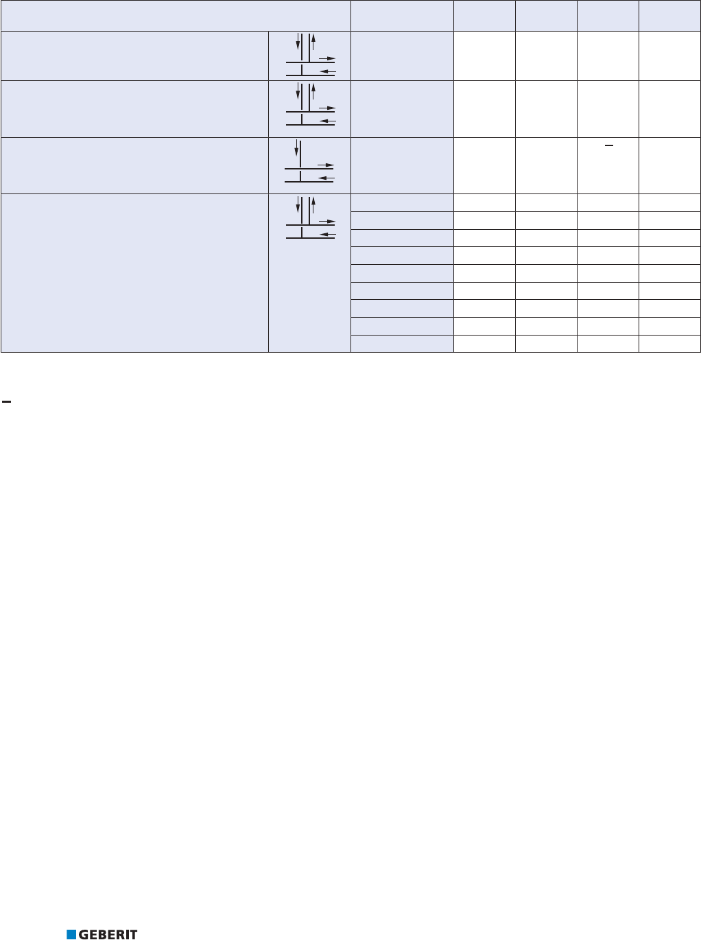
PRACTICAL USE CALCULATIONS WITH PRESSURE LOSSES
198
2.16.4 Pressure loss coefficients ζ for Geberit Mapress heating connections
Table99: Pressure loss coefficients ζ for Geberit Mapress heating connections
Heating connection with pressfitting d
[mm]
D
1
-ζ D
2
-ζ v
1
v
2
Inlet and return flow with clamping ring union
9
9
'
'
15–15
18–15
22–15
5.0 3.0 8.0 10.0
Inlet and return flow
9
9
'
'
15–15
18–15
22–15
28–15
5.0 3.0 6.0 8.0
Return flow
9
'
'
15–15
18–15
22–15
28–15
2.0 2.5 8.0
T-piece crossing with insulation box
9
9
'
'
12–12–12 0.6
1)
0.6
2)
0.8 1.6
15–12–12 0.3 0.3 0.6 1.6
15–12–15 0.6 0.6 0.6 1.7
18–12–18 1.3 1.3 0.5 2.7
22–12–22 1.1 1.1 0.5 9.3
15–15–15 0.6 0.6 0.9 1.5
18–15–18 1.3 1.2 0.8 3.2
22–15–22 1.1 1.3 0.8 6.8
22–18–22 1.1 1.3 2.3 6.5
1)
Calculated value
2)
Value adopted from similar geometry
Flow situation does not apply to any application.

PRACTICAL USE CALCULATIONS WITH PRESSURE LOSSES
199
2.16.5 Equivalent pipe length
The individual resistances can be taken into account in a simplified manner with the equivalent pipe length instead of the pressure loss
coefficient (Zeta value). The equivalent pipe length indicates which length of a straight pipe corresponds to the pressure loss of a fitting
or valve with a known individual resistance number.
The equivalent pipe length must be added to the pipe length and multiplied by the corresponding pipe friction pressure drop.
The equivalent pipe lengths corresponding to the individual resistances can be found in the tables entitled "Equivalent pipe lengths".
Equivalent pipe lengths
The equivalent pipe lengths were determined based on the EN 1267 and DVGW (W575) specifications.
Table100: Equivalent pipe lengths in metres Geberit Mapress, d12‒35mm
d
[mm]
12 15 18 22 28 35
Bend 90° (W90)
Y
0.18 0.22 0.26 0.33 0.42 0.54
Bend 45° (W45)
Y
0.14 0.17 0.19 0.25 0.3 0.4
T-piece
Branch fitting (TA)
Y
0.44 0.65 0.83 1.03 1.45 1.86
T-piece
Through-flow (TD)
Y
0.09 0.11 0.12 0.16 0.19 0.26
Threaded socket (K)
Y
0.08 0.09 0.09 0.12 0.12 0.17
Reducer (RED)
Y
18/12
0.1
22/15
0.07
22/18
0.08
35/22
0.09
54/28
0.12
42/35
0.14
Elbow tap connector 90°(WS)
Y
0.36 0.56 0.78 0.9
v The symbol v marks the reference cross-section.
The arrow marks the cross-sections flowing through during the measurement.
Flow situation does not apply to any application.
Table101: Equivalent pipe lengths in metres Geberit Mapress, d42‒108mm
d
[mm]
42 54 66.7 76.1 88.9 108
Bend 90° (W90)
Y
0.66 0.86 1.1 1.11 1.33 1.68

PRACTICAL USE CALCULATIONS WITH PRESSURE LOSSES
200
d
[mm]
42 54 66.7 76.1 88.9 108
Bend 45° (W45)
Y
0.47 0.6 0.7 0.66 0.78 0.99
T-piece
Branch fitting (TA)
Y
2.43 3.47 4.6 5.74 7.06 9.14
T-piece
Through-flow (TD)
Y
0.3 0.37 0.35 0.33 0.39 0.47
Threaded socket (K)
Y
0.18 0.19 0.49 0.12 0.15 0.19
Reducer (RED)
Y
54/42
0.16
88.9/54
0.22
76.1/66.7
0.26
108/76.1
0.12
108/88.9
0.15
Elbow tap connector 90°(WS)
Y
2 / 2
v The symbol v marks the reference cross-section.
The arrow marks the cross-sections flowing through during the measurement.
Flow situation does not apply to any application.
2.16.6 Square law of resistance
The pressure loss is in quadratic proportion to the volumetric flow rate. Consequently, half the volumetric flow rate still represents a
quarter of the pressure loss. The volumetric flow rate is therefore a factor that has a decisive influence on the pressure loss.
ୠS
ୠS
PEDU
PEDU
,ÃV
VÃ,
9
9
Δp
1
Pressure loss before the change [mbar]
Δp
2
Pressure loss after the change [mbar]
1
Volumetric flow rate before the change [l/s]
2
Volumetric flow rate after the change [l/s]

PRACTICAL USE EQUIPOTENTIAL BONDING
201
2.17 EQUIPOTENTIAL BONDING
Geberit Mapress is an electrically conductive piping system and must be integrated into the main equipotential bonding. The installer of
the electrical system must check whether equipotential bonding is included in the ready installed system.
The person installing the electrical system is responsible and accountable for the equipotential bonding.

PRACTICAL USE COMMISSIONING
202
2.18 COMMISSIONING
In addition to a professional installation, careful commissioning is required to ensure a perfect installation. The commissioning is
regulated in the respective country-specific edition of EN 14336:2004 as well as in other country-specific regulations.
The commissioning includes the following subtasks:
• pressure test
• initial filling
After the commissioning, the operator assumes responsibility for the proper operation of the installation.
2.18.1 General pressure test
Unpressed and inadequately screwed connections can be identified by means of a pressure test before commissioning the system.
The contractor is obliged to carry out a pressure test before closing up the masonry slits, wall and ceiling openings, and (where
applicable) before applying the screed or some other type of covering. The pressure test can be done on sections or on the complete
system. A visual check must be carried out before the pressure test to check whether the system has been installed properly.
The pressure test consists of two steps in conditions similar to those during operation:
1. Leak test: Checking the system for leaks. Unpressed and inadequately screwed connections can be identified in this way.
2. Load test: Checking the system for the quality of the material and processing.
The commissioning of a system may only take place if the pressure test has been completed successfully. A successfully completed
pressure test confirms to the customer that the pipe installation is leakproof and is to be documented with a test report.
2.18.2 Pressure test on drinking water installations
The pressure test checks the tightness of the pipe installation as well as the axial restraint of the connections. In principle, the local
regulations and/or standards must always be taken into account during the pressure test.
When using handheld pressure test pumps, for example in the test version for performing a strength test with drinking water, it is
important to ensure that the tools used are hygienically perfect. An appropriate measure is microfiltration of the test water before
feeding it into the drinking water installation.
Carrying out a pressure test must be regarded as a binding component of the installation. The test must be documented, for example,
by means of suitable protocols.
Pressure test using drinking water
Pay attention to the following basic rules for the pressure test with drinking water:
• The pressure test must be carried out directly before the commissioning for reasons of hygiene and chemical corrosion. If the
commissioning is not carried out directly after the installation, the system must remain full and a water replacement of the entire
drinking water installation must be carried out at regular intervals (at the latest after 7 days).
• Building heating must be provided for sub-zero ambient temperatures. Sub-zero temperatures do not warrant pressure testing with
compressed air.
• Temperature compensation must be carried out so that the filling water can adjust to the ambient temperature. If the ambient
temperature is higher than that of the filling water, the internal pressure rises due to the expansion caused by the heating. Whereas
if the ambient temperature is lower than the temperature of the filling water, the internal pressure drops. A visual inspection must
be carried out during the temperature compensation.
• The system must only be filled with hygienically perfect drinking water.
• Pressure measuring or recording instruments must be installed at the lowest point of the drinking water installation.
• Pressure measuring instruments must be used for the pressure test, which indicate pressure changes of 0.1 bar in a clearly legible
manner.

PRACTICAL USE COMMISSIONING
203
Carrying out the pressure test with drinking water
ü The adapter (outlet threaded nipple) is mounted on the test pipe.
ü The pressure test pump receptacle is filled with drinking water.
1 Seal the pipe ends, sanitary appliance and tap connectors with pressure test plugs.
2 Connect the pressure test pump and pressure measuring instrument at the lowest point of the piping system to be tested.
3 Fill the piping system slowly with drinking water and ventilate.
4 Slowly build up the pressure to 3 bar and maintain for 60 minutes in order to compensate for the temperature.
5 Set the pressure to 3 bar and test for 30 minutes for the leak test.
ð The pressure must be at least 2.5 bar after 30 minutes. If the pressure is <2.5bar, there are leaks in the piping system.
6 Check the tightness and insertion depth of all connections if the pressure is < 2.5 bar. Fix leaks.
7 Repeat the leak test until no more leaks can be detected.
8 For the strength test of the piping system, relieve the pressure from the leak test, do not empty.
9 Slowly build up the pressure to at least 15 bar or 1.5 times the operating pressure and test for 30 minutes. A maximum
pressure of 15 bar is admissible for pure plastic installations or mixed installations.
ð The pressure must be at least 12 bar after 30 minutes. If the pressure is <12bar, there are leaks in the piping system that
must be inspected and fixed.
2.18.3 Pressure test for natural gas installations
The pressure test for natural gas systems must be understood as a recommendation on the part of Geberit.
A basic distinction is made between installations by dividing them into low pressure and medium pressure gas installations on the basis
of their operating pressure. Tests should be performed in accordance with the following criteria:
Low pressure gas installations
• Pipelines with an operating pressure of up to and including 100 mbar must undergo a load test and leak test.
• The measuring instruments used must have a minimum resolution of 100 mbar.
Medium pressure gas installations
• Pipes with operating pressures ranging from 100mbar to 1 bar must undergo a combined load and leak test.
• A Class 1 pressure recorder and a Class 0.6 manometer must be used as measuring instruments for the pressure test.

PRACTICAL USE COMMISSIONING
204
2.18.4 Pressure testing of gas installations
In principle, the pressure test for gas installations can be performed using the following test media:
• oil-free compressed air
• inert gas (e.g. nitrogen)
Pressure test for natural gas installations
The pressure test for natural gas systems must be understood as a recommendation on the part of Geberit.
A basic distinction is made between installations by dividing them into low pressure and medium pressure gas installations on the basis
of their operating pressure. Tests should be performed in accordance with the following criteria:
Low pressure gas installations
• Pipelines with an operating pressure of up to and including 100 mbar must undergo a load test and leak test.
• The measuring instruments used must have a minimum resolution of 100 mbar.
Medium pressure gas installations
• Pipes with operating pressures ranging from 100mbar to 1 bar must undergo a combined load and leak test.
• A Class 1 pressure recorder and a Class 0.6 manometer must be used as measuring instruments for the pressure test.
2.18.5 Rules for the pressure testing of heating and water heating installations
The following must be observed for the pressure testing:
• The contractor must carry out a pressure test on the system after installation and before closing the wall channels, wall and ceiling
openings, and (where applicable) before applying the screed or some other type of covering.
• Water heating systems must be tested with a pressure that corresponds to the pressure of the relief valve.
• An additional visual check of each pressed joint is also used to check the axial restraint of the connections. It is therefore
imperative to check whether a connection has been pressed (pressing indicator is no longer available).
Guidelines in BS EN14336 can be followed.
2.18.6 Initial filling and flushing
The filling of a drinking water installation must only be carried out through a sufficiently flushed service connection pipe. The flushing of
the service connection pipe must be carried out in accordance with the water supply specifications before the installation of the
domestic water meter. It is important to ensure that there are sufficient drainage options.
Ideally, the flushing of drinking water pipes should take place at least 72 hours before the intended operation of the installation. The
flushing process must be carried out separately for the cold and hot water installation. The initial filling and flushing must be
documented.

Geberit Sales Ltd.
Geberit House
Edgehill Drive
GB-CV34 6NH Warwick
T: +44 (0)1926 516800
F: +44 (0)1926 400101
www.geberit.co.uk
971.620.00.0(00) © Geberit Sales Ltd.
Protected by copyright. No part of this publication may be reprinted or published in any form or by
any means, electronic or mechanical, without the prior permission of Geberit Sales Ltd.
