
Tangless
®
AND Tanged
INSERTS & TOOLS
The single best source for helical coil inserts, tools and thread repair kits in the industry.

BS EN ISO 9001: 2000, Amended May 2003.
Certificate No. FM 20982
All dimensions expressed in inches unless
otherwise specified. Specifications subject to
change without notice.
KATO
®
Tangless
®
and Tanged CoilThread
®
Inserts and Tools are covered by existing
U.S. and foreign patents.
Tangless
®
, KATO
®
, CoilThread
®
, and
CoiLock
®
are all Registered Trademarks of
Kato Fastening Systems, Inc., and the
Advanex Group.
KATO
®
Fastening Systems Mission Statement:
"We F.A.S.T.E.N."
• FUTURE: At KFS our goal is to assure that our products stay a step ahead of the
fastener needs of the future. "We think tomorrow… today!"
• ADVANCED
:
Our manufacturing and quality systems are the most advanced in the
industry, and we have licensed this technology to our largest competitors!
• SERVICE: Satisfaction- Plus™ is your guarantee that if you are not satisfied with any
of our products, for any reason — simply return the unused parts for replacement, or
a full refund. No other insert manufacturer can make that promise!
• TECHNOLOGY: Our technology is recognized as being the best in the industry. Using
our network of global resources, we developed the innovative line of Tangless®
Inserts & Tools!
• EXCELLENCE: Our goal is for the KFS name to be synonymous with an unsur-
passed level of excellence and distinction in the industry.
• NEXT: Complacency is not in our vocabulary. We are constantly working on the
next generation of fasteners and tools.
Copyright KFS 2003 15M
ISO Certification
1
Tangless or Tanged...it’s your choice. Your best
source for both is CoilThread
®
from KATO
®
!
Tangless Inserts:
FOD-Free Design: No tangs to break off, retrieve...or lose.
Approved for use on military programs by NASM8846 and NAS1130.
Cost Reduction: Significantly decreased installation and inspection time.
Bi-directional design eliminates insert orientation requirement.
Quick, non-destructive removal prevents damage to castings.
Tangless Inserts meet the requirements of NAS1130 and NASM8846, and were added to NASM8846, the
procurement standard for helical coil inserts to give you the option to use the Tangless design on military
programs. Paragraph 6.3.1 of NASM8846 states “The decision to select tanged inserts or tangless
inserts shall be made by the design activity.”
Tangless Inserts are designed to replace tanged helical coil inserts as specified
in NASM122076 and NASM124651 series (standard thread) and NASM21209
(locking thread); they install in standard STI tapped holes per NASM33537.
Installed inserts provide a finished thread meeting the requirements
of FED-STD-H28/2 and accept standard bolts or screws (MIL-S-7742)
or UNJ (MIL-S-8879).
Tanged Inserts:
Lower pricing than competitive inserts.
Complete range of locking and free-running sizes, bulk or strip-feed, including metric.
Full line of taps, gages, hand tools, air tools, and electric tools
available...interchangeable with and will install all major brands
of inserts.
Meet or exceed all applicable military, aerospace, and
commercial standards. Full traceability.
Design and Application Assistance: over 25 years of
manufacturing and engineering experience.
®

2
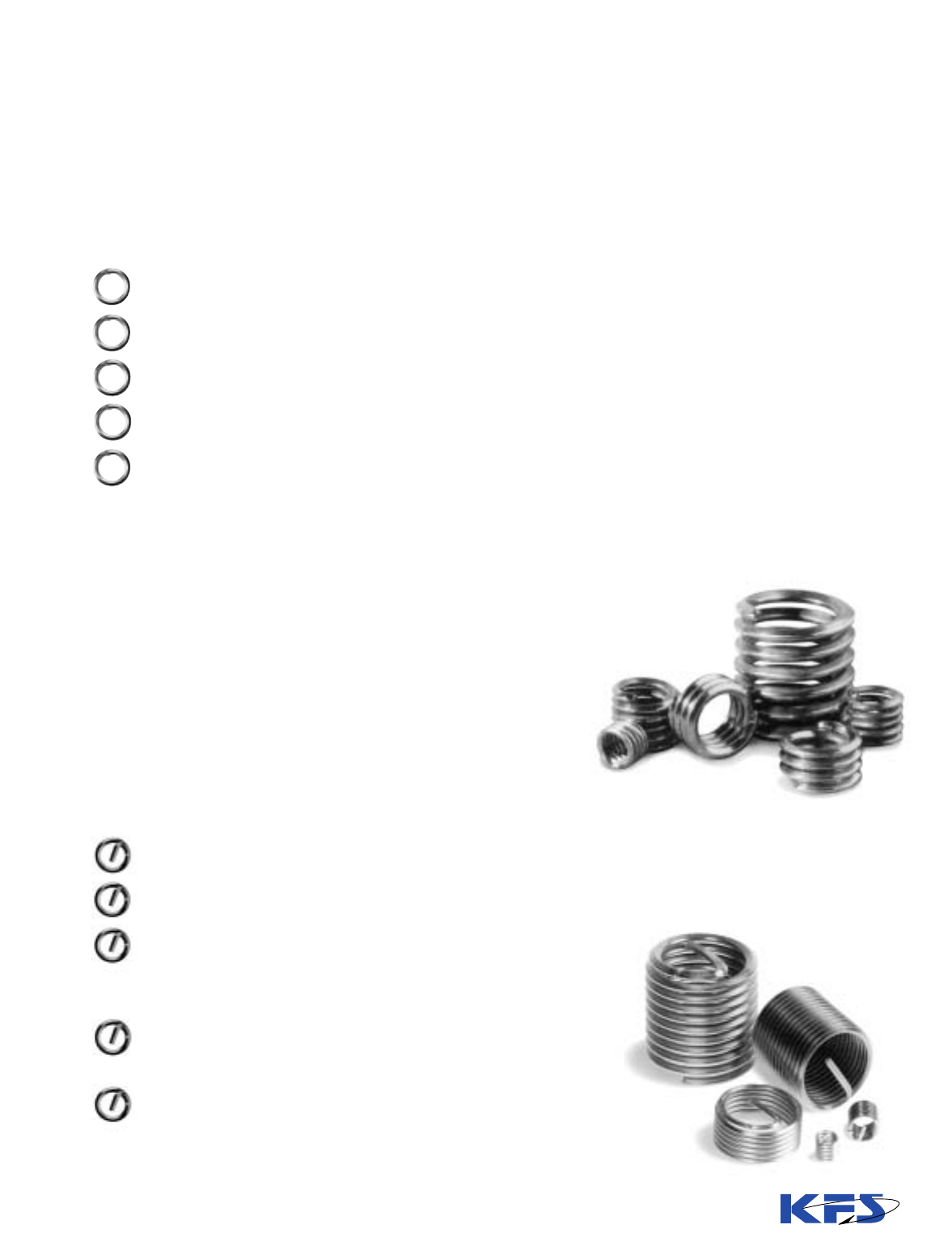
In either their tanged or Tangless configurations,
CoilThread Inserts are economical, helically-coiled fasten-
ing devices that provide permanent, wear-resistant screw
threads that exceed the strength of most parent materials.
They protect tapped threads against failures due to strip-
ping, seizing, corrosion and wear. They save time and
money because of their low initial cost and permit flexibili-
ty of installation when using Kato tools detailed in the tool-
ing section of the catalog.
CoilThread Inserts are made of cold-rolled Type 304 stain-
less steel wire (AS7245), work-hardened to a tensile
strength above 200,000 psi and a hardness of Rc43-50.
The finished surface (8-16 microinches) is exceedingly
smooth, virtually eliminating friction-induced thread ero-
sion.
When assembled in STI tapped holes, CoilThread Inserts
form Unified Coarse or Unified Fine threads that conform to
National Bureau of Standards Handbook H-28, Screw-
Thread Standards for Federal Services, Classes 2B and 3B.
Assembled CoilThread Inserts will also accommodate UNJ,
MIL-S-8879, male threaded fasteners.
Contents Pages
Tanged and Tangless
®
CoilThread
®
Helical Coil Inserts
–Inch and Metric Sizes
• Description . . . . . . . . . . . . . . . . . . . . . . . . . . . . . . . . . . . . . . . 2
• Performance and Features . . . . . . . . . . . . . . . . . . . . . . . . . . . . 3
• Applicable Standards . . . . . . . . . . . . . . . . . . . . . . . . . . . . . . . . 4
• Design Data . . . . . . . . . . . . . . . . . . . . . . . . . . . . . . . . . . . . . . . 5
• Installation Data . . . . . . . . . . . . . . . . . . . . . . . . . . . . . . . . . . . . 8
• STI Taps and Gages . . . . . . . . . . . . . . . . . . . . . . . . . . . . . . . . 14
Tangless CoilThread Inserts and Tools
–Inch Sizes
• Insert Selection . . . . . . . . . . . . . . . . . . . . . . . . . . . . . . . . . . . 19
• Cross Reference Table . . . . . . . . . . . . . . . . . . . . . . . . . . . . . . 20
• Prewinder-Type Hand Inserting Tools . . . . . . . . . . . . . . . . . . . 22
• Air Driven Inserting Tools. . . . . . . . . . . . . . . . . . . . . . . . . . . . 22
• Keyless Chuck Electric Driver . . . . . . . . . . . . . . . . . . . . . . . . . 23
• Hex Shank Insertion Mandrels . . . . . . . . . . . . . . . . . . . . . . . . 24
• Mandrel-Type Inserting and Removal Tools. . . . . . . . . . . . . . . 24
Tangless CoilThread Inserts and Tools
–Metric sizes
• Insert Selection . . . . . . . . . . . . . . . . . . . . . . . . . . . . . . . . . . . 26
• Prewinder-Type Hand and Hex Shank Inserting Tools . . . . . . . 28
• Removal Tools . . . . . . . . . . . . . . . . . . . . . . . . . . . . . . . . . . . . 28
• Air Driven Inserting Tools. . . . . . . . . . . . . . . . . . . . . . . . . . . . 29
Tanged CoilThread Inserts and Tools
–Inch Sizes
• Insert Selection . . . . . . . . . . . . . . . . . . . . . . . . . . . . . . . . . . . 30
• Cross Reference Table . . . . . . . . . . . . . . . . . . . . . . . . . . . . . . 31
• Hand Inserting Tools . . . . . . . . . . . . . . . . . . . . . . . . . . . . . . . 37
• Air Driven Inserting Tools. . . . . . . . . . . . . . . . . . . . . . . . . . . . 38
• Electric Inserting Tools. . . . . . . . . . . . . . . . . . . . . . . . . . . . . . 40
• Tang Break-Off & Extracting Tools . . . . . . . . . . . . . . . . . . . . . 42
Tanged CoilThread Inserts and Tools
–Metric sizes
• Insert Selection . . . . . . . . . . . . . . . . . . . . . . . . . . . . . . . . . . . 43
• Cross Reference Table . . . . . . . . . . . . . . . . . . . . . . . . . . . . . . 45
• Hand Inserting Tools . . . . . . . . . . . . . . . . . . . . . . . . . . . . . . . 48
• Air Driven Inserting Tools. . . . . . . . . . . . . . . . . . . . . . . . . . . . 49
• Electric Inserting Tools. . . . . . . . . . . . . . . . . . . . . . . . . . . . . . 49
• Tang Break-Off & Extracting Tools . . . . . . . . . . . . . . . . . . . . . 50
Kato-Kits
TM
- Thread Repair Kits
• Inch Size Kits. . . . . . . . . . . . . . . . . . . . . . . . . . . . . . . . . . . . . 51
• Metric Size Kits . . . . . . . . . . . . . . . . . . . . . . . . . . . . . . . . . . . 51
• Spark Plug & Pipe Thread Kits . . . . . . . . . . . . . . . . . . . . . . . . 53
HEXATORQ
TM
- Constant Torque Hinges. . . . . . . . 54
Tooling Guide - On Line. . . . . . . . . . . . . . . . . . . . . . . . . . 56
Technical Articles . . . . . . . . . . . . . . . . . . . . Inside back cover
CoilThread Inserts
®
CoilThread Inserts are precision-formed continuous heli-
cal coils. With minimal wall thickness, they are the most
compact and lightweight inserts available.
Cross section view shows just how little extra hole diam-
eter is needed to provide the outstanding thread strength
that CoilThread inserts offer.
®

3
HIGH TENSION ANCHOR
The high tensile coils of a CoilThread Insert undergo a diam-
eter reduction during installation. The outward spring-like
force of the coils“locks” the insert into place.
Each coil can flex independently to contact the greatest
amount of parent material thread surface. Both static and
dynamic load bearing capabilities are improved.
PARENT
MATERIAL
Performance & Features
CoilThread inserts improve the reliability of fastening systems.
The resilient characteristics of each coil in the
CoilThread insert allows it to adjust independently to
secure the maximum surface contact with individual
threads in the parent material. As a result, loads are
distributed more evenly. Stress and fatigue concen-
trations are reduced to maximize thread strength and
increase the reliability and life of the fastening
system.
The stainless steel used resists corrosion under nor-
mal environmental conditions. Galvanic action with-
in the thread assembly is reduced, further adding to
the life of the fastening assembly. These inserts are
used with temperatures from –320° F. to +800° F.
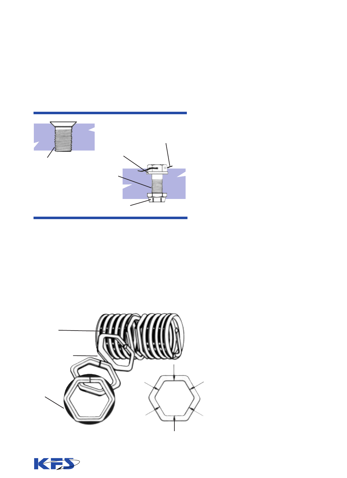
TANG
Used to drive insert into
tapped hole. Can be left
attached or removed per
requirements of the
application.
PREFORMED NOTCH
Simplifies removal of tang
if required.
DIAMOND SHAPED
CROSS SECTION
Keeps insert weight to a
minimum and allows the
smallest possible hole
diameter.
HARD WEAR-RESISTANT THREADS
Work-hardened, stainless steel forms a smooth, hard surface
that reduces thread wear and resists corrosion. Result: A highly
reliable, long-life insert.
COILOCK THREAD
LOCKING ELEMENT
CoiLock Self-Locking
Inserts incorporate one
or more coils with
straight run segments
that apply pressure to
and lock the threads of
the male fastener.
Additional information on
these Self-Locking
Inserts can be found on
Pages 6 and 7.
CoilThread Inserts provide design and
manufacturing flexibility.
Design opportunities are provided by the structure of
these inserts. Because of the continuous helically-coiled
design, they need no thick wall structure to support the
internal and external threads: the diamond-shaped coil is
the thread!
The inserts can be installed in reduced-size bosses or
flanges and within constricted areas, thus saving space
and weight while providing high strength. A boss radius
equal to the nominal bolt diameter is usually sufficient.
KATO Tools provide a choice of installation methods best
suited to specific production techniques. Convenient
hand tools can be supplied for small runs, repairs and
prototyping: or high-speed electric or air-powered tools
may be selected for rapid, low-cost installation.
CoilThread Inserts are available in Bulk and on Strip Feed
Reels...providing flexibility for any production set-up.
INDEPENDENT THREAD COILS

4
Corrosion Protection:
Corrosion is the deterioration of a metal because of a reaction
with its environment. The products of corrosion vary widely
from the flaky red rust of iron to the relatively benign oxide over
aluminum. In general, corrosion should be avoided or mini-
mized where possible.
There are many types of corrosion, but a particular type called
galvanic corrosion is most important for inserts and fasteners.
Galvanic corrosion occurs when dissimilar metals are in con-
tact in the presence of an electrolytic solution. All metals exhib-
it different degrees of “activity” or “nobility” and can be
arranged in a galvanic series of increasing activity. Gold and
platinum are most noble while zinc and magnesium are most
active. The most common electrolytic solution encountered is
ordinary water. Seawater or salt spray is more damaging
because of high concentrations of dissolved salts.
The best way to preclude galvanic corrosion is to use similar
potential metals and eliminate the electrolyte conductor. The
active stainless steel CoilThread Inserts are not passivated. This
minimizes the possibility of galvanic corrosion occurring when
they are installed in aluminum or magnesium parent materials.
Some additional precautions for reducing galvanic corrosion
are:
1. Isolate the fasteners from the electrolyte. This can be done
through gasketing or sealing.
2. Specify cadmium plated inserts. The cadmium plate pro-
vides a sacrificial barrier against corrosion. In addition, the cad-
mium plate has lubricating properties that minimize galling
when stainless steel screws are used.
3. Apply corrosion inhibiting pastes or compounds to the
screw. These include zinc chromate primer (MIL-P-8585) and
strontium chromate primer (MIL-P-23377). Note: Pastes
applied to the CoilThread Insert can become trapped between
the wire and the hole and cause loss of proper tolerance. It is
therefore recommended to apply the paste only to the screw,
not the insert. If zinc chromate primer is applied to the tapped
hole it should be thinned and applied sparingly. The insert
should be installed while the primer is still wet.
4. Specify a dry film lubricant such as molybdenum disulphide
on the inserts. This provides a secondary barrier against cor-
rosion.
5. Where practical or where it will not interfere with the com-
pleted assembly, the external joint should be coated with a suit-
able paint.
Military, Aerospace &
Commercial Standards
Performance & Features, continued
CoilThread Tanged and Tangless
®
Inserts are precision-
engineered and have been put through rigorous torque,
tension and vibration tests as well as comprehensive
dimensional inspections and metallurgical analysis in
attaining their MIL-Spec qualifications.
CoilThread Inserts have been thoroughly tested by an
independent testing laboratory and are certified to con-
form to NASM8846. Copies of these reports are available
upon request.
In addition, CoilThread Inserts and Tools are in confor-
mance with the following military standards and other
specifications:
Unified Inserts
NASM122076 series* – Insert, Corrosion Resistant
Helical Coil Coarse Thread
NASM124651 series* – Insert, Corrosion Resistant
Helical Coil Fine Thread
MS21208 – Insert-Screw Thread Free Running
(Superceded by MS122076 and
MS124651 series)
NASM21209* – Insert-Screw Thread Screw-Locking
NASM33537 – Assembly and Dimensions,
Helical Coil Inserts
NASM8846* – Inserts, Screw thread, Helical Coil
A-A-59158 – Tools for Inserting and Extracting
Helical Coil Inserts
AS7245 – Insert, Screw Thread, Helical Coil,
Corrosion Resistant Steel
QQ-P-416 – Cadmium Plating (Type II)
- Optional coating
AS5272 – Dry Film Lubricant (Type I)
- Optional coating
NAS1130 – Tangless Inserts, Free-running &
Locking
ASME B18.29.1 – Helical Coil, Screw Thread Inserts -
Free-Running & Locking
Metric Inserts
MA3279 – Inserts, Metric, Free-Running,
Helical Coil, Uncoated
MA3280 – Inserts, Metric, Free-Running,
Helical Coil, Lubricated
MA3281 – Inserts, Metric, Free-Running, Helical
Coil, Cadmium Plated
MA3329 – Inserts, Metric, Locking,
Helical Coil, Uncoated
MA3330 – Inserts, Metric, Locking,
Helical Coil, Lubricated
MA3331 – Inserts, Metric, Locking, Helical Coil,
Cadmium Plated.
MA1565 – Procurement Standard, Metric
Helical Coil Inserts
MA1567 – Assembly Dimensions,
Metric Helical Coil Inserts
* Note: In 1998 and 1999, the Military Specifications (MS) of the same
number were superceded by the NASM specifications.

2 2-1/2 3 3 ———— —
1-1/2 1-1/2 2 2-1/2 2-1/2 3 3 — —
1 1-1/2 1-1/2 2 2 2 2-1/2 3 3
111-1/2 1-1/2 1-1/2 2 2 2-1/2 2-1/2
1111-1/2 1-1/2 1-1/2 2 2 2-1/2
1 11111-1/2 1-1/2 1-1/2 2
1 1111111-1/2 1-1/2
Selection of Correct Insert Length
CoilThread Inserts are available in nominal thread sizes
from UNC #2 through 1-1/2,” and from UNF #3 through
1-1/2.” Metric sizes include M2.2 through M12. Five
insert lengths are available for each thread size.
It is important to select the correct insert length in order
to balance the bolt tensile strength against the shear
strength of the parent material.
These five insert lengths (recommended thread engage-
ment of the CoilThread Insert), 1, 1-1/2, 2, 2-1/2 and 3
are shown in the shaded area of the table below. These
are calculated numbers since the inserts cannot be
measured in the free state. The numbers are multiples of
the nominal thread size, or diameter, of the insert. The
actual insert lengths in the installed position are listed in
the insert selection tables. There they represent the
actual installed length plus 1/2 pitch.
Using the table below, an insert length can be selected
which will produce a thread system strong enough to
fracture a bolt before it will strip or damage either the
parent material or the insert.
Recommended Nominal Insert lengths Based on
Parent Material Versus Bolt Material Strengths
UNIFIED
Design Data
EXAMPLE: If parent material shear strength is 10KSI and the bolt tensile
strength is 54 KSI, the correct insert length is 2 diameters.
Shear Strength of
Parent Material
MPa(megapascals)
(Alum., Mag., Steel)
Bolt Ultimate Tensile Strength
MPa (megapascals)
300
1-1/2
1
1
1
1
1
1
70
100
150
200
250
300
350
400
2
1-1/2
1
1
1
1
1
500
2-1/2
1-1/2
1-1/2
1
1
1
1
600
2-1/2
2
1-1/2
1
1
1
1
800
–
2-1/2
2
1-1/2
1
1
1
1000
–
3
2
1-1/2
1-1/2
1-1/2
1
1200
–
–
2-1/2
2
1-1/2
1-1/2
1-1/2
1400
–
–
3
2-1/2
2
1-1/2
1-1/2
METRIC
Bolt Projection
Standard, readily available bolts and screws that require
no special hardware are used with CoilThread Inserts.
The bolt must engage the entire insert length to achieve
maximum assembly strength. To insure against partial
engagement, it is recommended that the tang always be
removed. This will also guarantee that the locking coil(s)
will be engaged by the full threads of the bolt. If design
parameters prevent this, contact the KATO Engineering
Department for assistance.
NOTES:
1. Bolt tensile strengths are specified minimums. When
choosing an insert length, consideration should be
given the maximum tensile strength allowed by the
bolt drawing or procurement
specification.
2. Service temperatures can cause significant variations
in strength values, therefore compensation should
be allowed.
3. The importance of shear values should be kept in
mind because the parent material is subject to shear
ing stress near the major diameter of the tapped
threads.
4. When the strength values fall between two values in
the table above, use next lower material shear value,
or the next higher bolt tensile strength value.
5. To achieve maximum strength, bolt length and thread
length as well as full tapped thread depth must be
sufficient to assure full thread engagement over the
entire length of the insert.
6. Specific charts detailing load values by thread size
are available: contact the KATO Engineering
Department.
Shear Strength
of Parent
Material (KSI)
Bolt Material Minimum
Ultimate Tensile Strength (KSI)
54 75 96 108 125 132 160 180 220
10
15
20
25
30
40
50
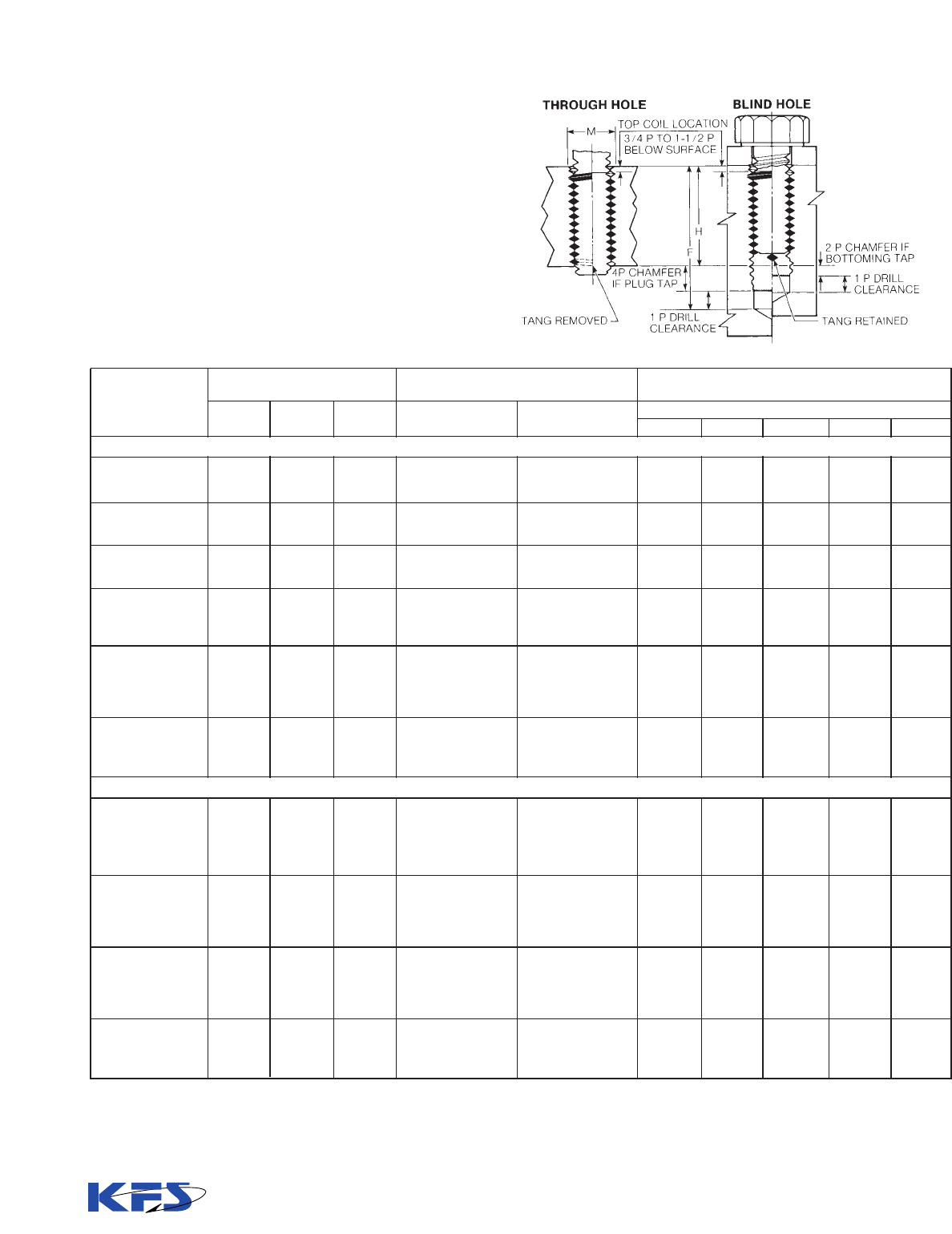
TANG
REMOVED
H DIM.
(MIN. TAP DEPTH
F DIM.
(MIN.
DRILLED
HOLE
DEPTH)
5
6
CoiLock Inserts exert a prevailing torque on male thread-
ed fasteners to prevent loosening due to vibration or
impact. They eliminate the need for other, less desirable
and costly locking mechanisms. They are excellent in
adjusting screw applications by preventing the male fas-
tener from creeping.
How CoiLock Inserts work
One or more of the coils in the insert have a series of
straight segments. Upon entry of the bolt these straight
segments are flexed outwardly, creating pressure on the
bolt. This pressure is applied between the flanks of the
bolt thread so that contact area is maximized and unit
pressure is minimized. It is often possible to realize cycle
life far in excess of specification requirements.
CoiLock Self-Locking Inserts – Tangless & Tanged
®
®
Location of Locking Coils
For 1, 1
1
/
2
, and 2 diameter lengths: The center of the lock-
ing coil (or coils) equals
1
/
2
the number of free coils. For
2
1
/
2
and 3 diameter lengths: The locking coil is located
the same distance from the tang as 2 diameter length
inserts. For Tangless inserts, the center of the locking
coil equals
1
/
2
the number of free coils.
Locking Torques
Unified size CoiLock Inserts conform to NASM21209
(Tanged) and NAS1130 (Tangless) and produce locking
torques in accordance with NASM8846 when used with
heat treated cadmium-plated bolts. When using heat
treated unplated or stainless steel bolts, an anti-seize
compound, e.g., molybdenum disulfide, must be used in
order to minimize galling and assure maximum cycle
life. Wear life of screw or bolt using CoiLock Inserts can
also be improved by specifying dry film lubrication or
cadmium plating.
KATO engineers are available for consultation on appli-
cations using brass or aluminum screws, low torque
adjusting screws and severe high torque requirements.
CoiLock inserts in Unified sizes are dyed red for easy
identification purposes only. It is alcohol soluble and can
be removed if desired. (Metric locking inserts are not
dyed red.)
COILOCK
SELF-LOCKING
INSERT
COILOCK
SELF-LOCKING
INSERT
POLYGONAL
COILTHREAD COIL
CIRCULAR,
STANDARD
COILTHREAD
COIL
CHEMICAL
COMPOUNDS
LOCK WASHER
SAFETY WIRE
CoiLock Self-Locking Inserts
eliminate the need for external
fastener locking components.
Locking coil segments exert prevailing
torque between the thread flanks of
the screw or bolt to resist loosening.
LOCK NUT

7
Min.
Locking Torque
15th Cycle
Max.
Locking
Torque
Nominal
Thread Size
Locking torque values for Metric CoilThread Inserts conform
to ISO2320, when tested in accordance with NASM8846.
For convenience these locking torque limits are shown above
in Newton-meters.
Locking torque values for Unified CoilThread Inserts conform
to NASM8846.
M2.2x0.45
M2.5x0.45
M3x0.5
M3.5x0.6
M4x0.7
M5x0.8
M6x1
M7x1
M8x1.25
M10x1.5
M12x1.75
M14x2
M16x2
M18x2.5
M20x2.5
M22x2.5
M24x3
0.14 N.m.
0.23 N.m.
0.45 N.m.
0.68 N.m.
0.9 N.m.
1.6 N.m.
3 N.m.
4.5 N.m.
6 N.m.
10.5 N.m.
15.5 N.m.
23 N.m.
31.5 N.m.
42 N.m.
54 N.m.
67.5 N.m.
80 N.m.
0.02 N.m.
0.05 N.m.
0.1 N.m.
0.12 N.m.
0.15 N.m.
0.3 N.m.
0.4 N.m.
0.6 N.m.
0.8 N.m.
1.4 N.m.
2.1 N.m.
3 N.m.
4.2 N.m.
5.5 N.m.
7 N.m.
9 N.m.
10.5 N.m
M8x1
M10x1
M10x1.25
M12x1.25
M12x1.5
M14x1.5
M16x1.5
M18x1.5
M20x1.5
M22x1.5
M18x2
M20x2
M22x2
M24x2
6 N.m.
10.5 N.m.
10.5 N.m.
15.5 N.m.
15.5 N.m.
23.5 N.m.
31.5 N.m.
42 N.m.
54 N.m.
67.5 N.m.
42 N.m.
54 N.m.
67.5 N.m.
80 N.m.
0.8 N.m.
1.4 N.m.
1.4 N.m.
2.1 N.m.
2.1 N.m.
3 N.m.
4.2 N.m.
5.5 N.m.
7 N.m.
9 N.m.
5.5 N.m.
7 N.m.
9 N.m.
10.5 N.m
Nominal
Thread Size
2 (.086)-56
3 (.099)-48
4 (.112)-40
5 (.125)-40
6 (.138)-32
8 (.164)-32
10 (.190)-24
12 (.216)-24
1/4 (.250)-20
5/16 (.3125)-18
3/8 (.3750)-16
7/16 (.4375)-14
1/2 (5000)-13
9/16 (.5625)-12
5/8 (.6250)-11
3/4 (.7500)-10
7/8 (8750)- 9
1 (1.0000)- 8
1-1/8 (1.1250)- 7
1-1/4 (1.2500)- 7
1-3/8 (1.3750)- 6
1-1/2 (1.5000)- 6
3 (.099)-56
4 (.112)-48
6 (.138)-40
8 (.164)- 36
10 (190)- 32
1/4 (.250)- 28
5/16 (.3125)- 24
3/8 (.3750)- 24
7/16 (.4375)- 20
1/2 (.5000)- 20
9/16 (.5625)- 18
5/8 (.6250)- 18
3/4 (.7500)- 16
7/8 (.8750)- 14
1 (1.0000)- 12
1-1/8 (1.1250)- 12
1-1/4 (1.2500)- 12
1-3/8 (1.3750)- 12
1-1/2 (1.5000)- 12
Max.
Locking
Torque
20 oz-in
32 oz-in
48 oz-in
75 oz-in
6 lb-in
9 lb-in
13 lb-in
24 lb-in
30 lb-in
60 lb-in
80 lb-in
100 lb-in
150 lb-in
200 lb-in
300 lb-in
400 lb-in
600 lb-in
800 lb-in
900 lb-in
1000 lb-in
1150 lb-in
1350 lb-in
32 oz-in
48 oz-in
6 lb-in
9 lb-in
13 lb-in
30 lb-in
60 lb-in
80 lb-in
100 lb-in
150 lb-in
200 lb-in
300 lb-in
400 lb-in
600 lb-in
800 lb-in
900 lb-in
1000 lb-in
1150 lb-in
1350 lb-in
Min.
Locking Torque
15th Cycle
3 oz-in
7 oz-in
10 oz-in
13 oz-in
1.0 lb-in
1.5 lb-in
2.0 lb-in
3.0 lb-in
4.5 lb-in
7.5 lb-in
12.0 lb-in
16.5 lb-in
24.0 lb-in
30.0 lb-in
40.0 lb-in
60.0 lb-in
82.0 lb-in
110.0 lb-in
137.0 lb-in
165.0 lb-in
185.0 lb-in
210.0 lb-in
7 oz-in
10 oz-in
1.0 lb-in
1.5 lb-in
2.0 lb-in
3.5 lb-in
6.5 lb-in
9.5 lb-in
14.0 lb-in
18.0 lb-in
24.0 lb-in
32.0 lb-in
50.0 lb-in
70.0 lb-in
90.0 lb-in
117.0 lb-in
143.0 lb-in
165.0 lb-in
190.0 lb-in
Unified Fine
Unified Coarse
Fine
Coarse
Torque Limits, Inch Torque Limits, Metric
To Convert From To Multiply By
N.m. oz-in 141.6119
N.m. lb-in 8.850748
oz-in N.m. 0.0070615
lb-in N.m. 0.1129848
Torque Units -Conversion Factors

8
Drilling the Hole:
Drilled hole dimensions are tabulated on pages
10–13. The minor diameters tabulated conform to
NASM33537 (inch sizes), and MA1567 (metric sizes), and
must be met after tapping.
The drill sizes shown are recom-
mendations only, based on expected
material behavior and for increased
tap life in harder materials. Actual
individual conditions may require
varied drill sizes in order to produce
the correct minor diameter after
tapping.
The Minimum Drilled Hole Depth is designed to allow for:
1. The use of standard countersink as tabulated.
2. The use of standard Screw-Thread Insert (STI) plug or
bottoming tap for the maximum tool life.
3. The use of the standard installation set-down of 3/4 to 11/2
pitch below the work surface.
The “F” dimension minimum is based on installed insert
length, plus set-down, plus tap chamfer length, plus chip
clearance.
For plug taps with a nominal diameter of 5/16” or smaller the
“F” dimension minimum allows for a male center on the tap
equal in length to nominal tap diameter divided by 2.
Minimum Material Thickness for Through Holes:
The nominal insert length is the minimum through hole
length (material thickness) without counter-sinking and with
the insert located 1/4 to 1/2 pitch below the top surface. With
normal countersink and set-down, the minimum through
hole material thickness equals “H” dimension, the minimum
full thread depth...or minimum tapping depth shown tabulat-
ed on pages 10–13.
Edge Distance Minimum:
For most materials, a minimum edge distance equal to the
nominal bolt diameter may be used when measured from the
centerline of the hole.
Countersinking:
Countersinking dimensions are also tab-
ulated on Pages 11 and13. These con-
form to NASM33537 and MA1567.
Before tapping, it is good practice to
countersink 120° ± 5° to “M” diameter in
order to prevent a feather edge at the
start of the hole. The 60° per side coun-
tersink angle is used because it is the
same as the angles of the tapped thread, insert cross section
and inserting tool prewinder tip. This combination provides
for smooth and rapid production installation.
The “F” and “H” values are calculated with a
countersink depth of 1/2 pitch.
Tapping:
The pitch diameter limits shown tabulated
on pages 11 and 13 conform to
NASM33537 and MA1567 and must be
met in order to assure proper thread fit
after installation of the CoilThread Insert.
Installation Data –
Unified and Metric Sizes, Tanged & Tangless Inserts
Countersink with a
standard countersink.
Tap with KATO taps.
Drill with a standard
drill
CoilThread Inserts are normally installed
3/4 to 1-1/2 pitch below the surface of the
parent material in counter-sunk holes.
Modification of this set-down depth may
be made to suit certain limitations. Without
a countersink the inserts are typically
installed 1/4 to 1/2 pitch below the surface.
®

9
KATO STI Taps are for free machining materials. Four
styles are included see pages 14, 15, and 17):
1. Plug Style: Provides easy starting for through holes
and blind holes.
2. Bottoming Style: Ideal for blind holes that are drilled
to a minimum depth. Also for blind holes that require
threads to be close to the bottom of the hole.
3. Spiral Pointed Style (Plug): Free-cutting suited for
use in long through holes and in blind holes with
ample chip clearance.
4. Spiral Flute Style (Bottoming): Pulls chips out of
deep or blind holes in soft materials.
Roughing Taps are also available for use where tapping
operations are difficult. These reduce the load on the fin-
ishing tap. Contact KATO for availability.
As in drilling the tap “H” dimension limits are recommen-
dations only and may be varied where necessary to pro-
duce the required class of fit. CoilThread Inserts are iden-
tical for the various classes of fit. The class of fit is con-
trolled by the tapped hole tolerance.
The class of fit specifies the pitch diameter tolerance,
with 3B (inch) and 4H (metric) being the tighter ranges
and usually specified for military/aerospace applica-
tions. The tighter classes of fit are recommended when
using locking-type inserts for more consistent locking
torque. Class 2B (inch) and 5H (metric) tapped holes
provide a broader tolerance range, and are frequently
specified for commercial/industrial and thread repair
applications.
The minimum tap depth “H” dimension is calculated for use
of a standard countersink and standard insert set-down
depth. Modification of set-down or elimination of counter-
sink will permit a corresponding reduction in thread depth.
All tapped hole dimensions must be met after application of
any desired surface finish such as anodize.
Gaging:
KATO STI Plug Gages used to check the tapped holes are
described on pages 16 and 18.
Working gages are recommended for production use
since their greater tolerance allows for more wear.
Reference gages have pitch diameters at or very close to
basic size and are to be used as master gages.
Installation of the Tanged CoilThread Inserts:
CoilThread Inserts may be installed with tools conforming
to A-A-59158.
KATO tools for inserting, tang breakoff and insert extrac-
tion are also included on Pages 37-42 and 48-50.
The accuracy of the finished thread with the CoilThread
Insert installed depends upon the accuracy of the tapped
hole. If the tapped hole gages correctly, the installed
CoilThread Insert will be within the thread tolerance. No
further gaging is necessary. If gaging is attempted after
the CoilThread is installed, the GO thread plug gage may
not enter freely...however, the insert will seat itself when
the bolt or screw is installed and tightened. (Reference
NASM33537 and MA1567)
Tang Removal:
It is recommended that the tang always be removed to
insure that the full threads of the bolt fully engage the
locking coils when using CoiLock Inserts. To achieve max-
imum assembly strength the bolt must engage the entire
insert length.
Note: If necessary, CoilThread inserts can be removed
from their tapped holes even after tangs have been
removed. Removal tools are listed on pages 42 and 50.
Power Tools:
For rapid installation, KATO Power Tools are available.
These are detailed on Pages 38-41 and 49.
“No Go” (Hi) “Go”
With needle nose pliers With automatic tool
10
Installation Data -
Unified Sizes
Drilled Hole Dimensions
2 (.086)-56 .0899 .0961 .0961 3/32 (.0938) #41 (.0960) .236 .279 .322 .365 .408
3 (.099)-48 .1036 .1104 .1104 #36 (.1065) 7/64 (.1094) .273 .323 .372 .422 .471
4 (.112)-40 .1175 .1252 .1252 #31 (.1200) #31 (.1200) .318 .374 .430 .486 .542
5 (.125)-40 .1305 .1373 .1373 3.4mm (.1339) #29 (.1360) .338 .400 .462 .525 .588
6 (.138)-32 .1448 .1527 .1527 #26 (.1470) #25 (.1495) .394 .464 .532 .602 .670
8 (.164)-32 .1708 .1781 .1781 #17 (.1730) #16 (.1770) .434 .516 .598 .680 .762
10 (.190)-24 .1990 .2080 .2087 13/64 (.2031) #5 (.2055) .535 .630 .725 .820 .915
12 (.216)-24 .2250 .2340 .2347 #1 (.2280) #1 (.2280) .574 .682 .790 .898 1.006
1/ 4(.250)-20 .2608 .2704 .2723 H (.2660) H (.2660) .675 .800 .925 1.050 1.175
5/16 (.3125)-18 .3245 .3342 .3372 Q (.3320) Q (.3320) .801 .957 1.113 1.269 1.425
3/8 (.3750)-16 .3885 .3987 .4026 X (.3970) X (.3970) .750 .938 1.125 1.312 1.500
7/16 (.4375)-14 .4530 .4639 .4688 29/64 (.4531) 29/64 (.4531) .867 1.086 1.305 1.524 1.743
1/2 (.5000)-13* .5166 .5273 .5335 33/64 (.5156) 17/32 (.5312) .962 1.212 1.462 1.712 1.962
9/16 (.5625)-12* .5806 .5918 .5986 37/64 (.5781) 19/32 (.5938) 1.062 1.343 1.624 1.905 2.186
5/8 (.6250)-11 .6447 .6564 .6641 21/32 (.6562) 21/32 (.6562) 1.170 1.483 1.795 2.108 2.420
3/4 (.7500)-10 .7716 .7838 .7926 25/32 (.7812) 25/32 (.7812) 1.350 1.725 2.100 2.475 2.850
7/8 (.8750)- 9 .8990 .9119 .9213 29/32 (.9062) 29/32 (.9062) 1.542 1.979 2.417 2.854 3.292
1 (1.0000)- 8 1.0271 1.0421 1.0521 1-1/32 (1.0312) 1-1/32 (1.0312) 1.750 2.250 2.750 3.250 3.750
1- 1/8 (1.1250)- 7 1.1559 1.1730 1.1834 1-11/64 (1.1719) 1-11/64 (1.1719) 1.982 2.545 3.107 3.670 4.232
1- 1/4 (1.2500)- 7 1.2809 1.2980 1.3084 1-19/64 (1.2969) 1-19/64 (1.2969) 2.107 2.732 3.357 3.982 4.607
1- 3/8 (1.3750)- 6 1.4110 1.4310 1.4416 1-27/64 (1.4219) 1-27/64 (1.4219) 2.375 3.062 3.750 4.437 5.125
1- 1/2 (1.5000)- 6 1.5360 1.5560 1.5665 1-35/64 (1.5469) 1-35/64 (1.5469) 2.500 3.250 4.000 4.750 5.500
3 (.099)-56 .1029 .1086 .1086 #37 (.1040) #36 (.1065) .256 .305 .355 .404 .454
4 (.112)-48 .1166 .1229 .1229 3mm (.1181) #31 (.1200) .293 .349 .405 .461 .517
6 (.138)-40 .1435 .1503 .1503 #26 (.1470) #25 (.1495) .357 .426 .495 .564 .633
8 (.164)-36 .1701 .1771 .1771 #17 (.1730) #16 (.1770) .413 .495 .577 .659 .741
10 (.190)-32 .1968 .2041 .2041 #7 (.2010) 13/64 (.2031) .472 .568 .662 .758 .852
1/4 (.2500)-28 .2577 .2646 .2661 G (.2610) 6.7mm (.2638) .589 .714 .839 .964 1.089
5/16 (.3125)-24 .3215 .3288 .3312 21/64 (.3281) 21/64 (.3281) .718 .874 1.030 1.186 1.342
3/8 (.3750)-24 .3840 .3910 .3937 25/64 (.3906) 25/64 (.3906) .625 .812 1.000 1.187 1.375
7/16 (.4375)-20 .4483 .4561 .4593 29/64 (.4531) 29/64 (.4531) .738 .957 1.176 1.395 1.614
1/2 (.5000)-20 .5108 .5186 .5223 33/64 (.5156) 33/64 (.5156) .800 1.050 1.300 1.550 1.800
9/16 (.5625)-18 .5745 .5826 .5872 37/64 (.5781) 37/64 (.5781) .895 1.176 1.457 1.738 2.019
5/8 (.6250)-18 .6370 .6451 .6497 41/64 (.6406) 41/64 (.6406) .958 1.271 1.583 1.896 2.208
3/4 (.7500)-16 .7635 .7720 .7776 49/64 (.7656) 49/64 (.7655) 1.125 1.500 1.875 2.250 2.625
7/8 (.8750)-14 .8905 .8994 .9063 57/64 (.8906) 57/64 (.8906) 1.304 1.741 2.179 2.616 3.054
1 (1.0000)-12
1
1.0181 1.0281 1.0361 1-1/64 (1.0156) 1-1/32 (1.0312) 1.500 2.000 2.500 3.000 3.500
1-1/8 (1.1250)-12
1
1.1431 1.1531 1.1611 1-9/64 (1.1406) 1-5/32 (1.1562) 1.625 2.187 2.750 3.312 3.875
1-1/4 (1.2500)-12
1
1.2681 1.2781 1.2861 1-17/64 (1.2656) 1-9/32 (1.2812) 1.750 2.375 3.000 3.625 4.250
1-3/8 (1.3750)-12
1
1.3931 1.4031 1.4111 1-25/64 (1.3906) 1-13/32 (1.4062) 1.875 2.562 3.250 3.937 4.625
1-1/2 (1.5000)-12
1
1.5181 1.5281 1.5361 1-33/64 (1.5156) 1-17/32 (1.5312) 2.000 2.750 3.500 4.250 5.000
Unified Coarse
Unified Fine
Nominal
Thread Size
Minor Diameter
(After Tapping)
Suggested Drill Size
1
F Dim.
2
Minimum Drilling Depth for Taps
Min. All
Classes
Max Class
3B
Max Class
2B
Aluminum
Steel Magnesium
Plastic
11
1
/2 2
1
/2
32
Plug Taps
1
Standard size drills are suggested even though in these sizes they vary slightly from minor diameter specifications in NASM33537.
2
For plug taps with a nominal diameter of 5/16” or smaller, (F) minimum allows for a male center on the tap equal in length to nominal tap diameter divided by 2.

11
.157
.182
.212
.225
.263
.289
.357
.383
.450
.534
.625
.724
.808
.895
.989
1.150
1.319
1.500
1.696
1.821
2.042
2.167
.200
.232
.268
.288
.332
.371
.452
.491
.575
.690
.812
.943
1.058
1.176
1.301
1.525
1.757
2.000
2.259
2.446
2.729
2.917
.243
.281
.324
.350
.401
.453
.547
.599
.700
.846
1.000
1.162
1.308
1.457
1.614
1.900
2.194
2.500
2.821
3.071
3.417
3.667
.286
.331
.380
.412
.470
.535
.642
.707
.825
1.002
1.188
1.381
1.558
1.738
1.926
2.275
2.632
3.000
3.384
3.696
4.104
4.417
.329
.380
.436
.475
.539
.617
.737
.815
.950
1.158
1.375
1.600
1.808
2.019
2.239
2.650
3.069
3.500
3.946
4.321
4.792
5.167
.09
.11
.14
.16
.18
.20
.24
.26
.31
.38
.45
.52
.59
.66
.73
.87
1.00
1.14
1.29
1.41
1.56
1.69
.11
.14
.17
.19
.21
.23
.27
.29
.34
.41
.48
.55
.62
.69
.76
.90
1.03
1.17
1.32
1.44
1.59
1.72
.0976
.1126
.1283
.1413
.1583
.1843
.2170
.2430
.2825
.3486
.4156
.4839
.5499
.6167
.6841
.8149
.9471
1.0812
1.2178
1.3428
1.4832
1.6082
.0989
.1140
.1299
.1430
.1601
.1862
.2192
.2453
.2851
.3515
.4189
.4875
.5537
.6208
.6885
.8196
.9522
1.0890
1.2239
1.3490
1.4900
1.6151
.0996
.1148
.1306
.1438
.1611
.1872
.2203
.2464
.2863
.3529
.4203
.4890
.5554
.6225
.6903
.8216
.9543
1.0868
1.2262
1.3514
1.4926
1.6177
.10
.12
.14
.15
.17
.20
.23
.26
.30
.37
.44
.51
.58
.65
.72
.85
.99
1.13
1.27
1.39
1.54
1.67
.15
.17
.19
.21
.24
.28
.33
.37
.43
.53
.63
.73
.83
.93
1.03
1.23
1.42
1.63
1.83
2.02
2.23
2.42
.19
.22
.25
.28
.31
.36
.42
.47
.55
.68
.81
.95
1.08
1.21
1.34
1.60
1.86
2.13
2.39
2.64
2.92
3.17
.23
.27
.31
.34
.38
.44
.52
.58
.68
.84
1.00
1.17
1.33
1.49
1.65
1.98
2.30
2.63
2.96
3.27
3.60
3.92
.28
.32
.36
.40
.45
.52
.61
.69
.80
.99
1.19
1.38
1.58
1.77
1.97
2.35
2.74
3.13
3.52
3.89
4.29
4.67
.1117
.1289
.1473
.1603
.1817
.2077
.2475
.2735
.3187
.3884
.4602
.5343
.6042
.6751
.7477
.8850
1.0247
1.1681
1.3171
1.4421
1.5982
1.7232
.01786
.02083
.02500
.02500
.03125
.03125
.04167
.04167
.05000
.05556
.06250
.07143
.07692
.08333
.09091
.10000
.11111
.12500
.14286
.14286
.16667
.16667
.170
.195
.238
.275
.315
.393
.479
.542
.638
.700
.784
.847
1.000
1.161
1.333
1.458
1.583
1.708
1.833
.220
.251
.307
.357
.410
.518
.635
.729
.857
.950
1.065
1.160
1.375
1.598
1.833
2.021
2.208
2.396
2.583
.269
.307
.376
.439
.505
.643
.791
.917
1.076
1.200
1.346
1.472
1.750
2.036
2.333
2.583
2.833
3.083
3.333
.319
.363
.445
.521
.600
.768
.947
1.104
1.295
1.450
1.627
1.785
2.125
2.473
2.833
3.146
3.458
3.771
4.083
.368
.419
.514
.603
.695
.893
1.103
1.292
1.514
1.700
1.908
2.097
2.500
2.911
3.333
3.708
4.083
4.458
4.833
.11
.13
.17
.20
.23
.29
.36
.42
.50
.56
.63
.69
.82
.96
1.10
1.22
1.35
1.47
1.60
.14
.16
.20
.23
.26
.32
.39
.45
.53
.59
.66
.72
.85
.99
1.13
1.25
1.38
1.50
1.63
.1106
.1256
.1543
.1821
.2103
.2732
.3395
.4020
.4700
.5325
.5986
.6611
.7906
.9214
1.0542
1.1792
1.3042
1.4292
1.5542
.1119
.1271
.1560
.1840
.2123
.2754
.3421
.4047
.4731
.5357
.6020
.6646
.7945
.9257
1.0589
1.1841
1.3092
1.4343
1.5595
.1126
.1279
.1569
.1849
.2133
.2765
.3433
.4059
.4744
.5371
.6035
.6661
.7961
.9274
1.0608
1.1860
1.3112
1.4364
1.5615
.12
.13
.16
.19
.22
.29
.35
.42
.49
.55
.62
.68
.81
.95
1.08
1.21
1.33
1.46
1.58
.17
.19
.23
.27
.32
.41
.51
.60
.71
.80
.90
.99
1.19
1.38
1.58
1.77
1.96
2.15
2.33
.22
.24
.30
.36
.41
.54
.67
.79
.93
1.05
1.18
1.31
1.56
1.82
2.08
2.33
2.58
2.83
3.08
.27
.30
.37
.44
.51
.66
.82
.98
1.14
1.30
1.46
1.62
1.94
2.26
2.58
2.90
3.21
3.52
3.83
.31
.36
.44
.52
.60
.79
.98
1.17
1.36
1.55
1.74
1.93
2.31
2.70
3.08
3.46
3.83
4.21
4.58
.1247
.1419
.1733
.2032
.2337
.2995
.3700
.4325
.5062
.5687
.6384
.7009
.8352
.9718
1.1126
1.2376
1.3626
1.4876
1.6126
.01786
.02083
.02500
.02778
.03125
.03751
.04167
.04167
.05000
.05000
.05556
.05556
.06250
.07143
.08333
.08333
.08333
.08333
.08333
Unified Coarse
Unified Fine
F Dim
Minimum Drilling Depth for Taps
H Dim
Minimum Tapping Depth
Bottoming Taps
Countersink M
Diameter
(120°± 5° included angle)
Pitch Diameter
Diameter
11
1
/2
2
1
/2
3 Min.
Min.
3B
Max.
2B
Max.
Tap
Major
Dia.
Max.
Thread
Pitch
P
Max.211
1
/2
2
1
/2
32
Tapped Hole Dimensions-
Unified Sizes

M8x1 8.217 8.407 21/64 ( .3281) 21/64 ( .3281)
M10x1 10.217 10.407 Y ( .4040) 13/32 ( .4062)
M10x1.25
1
10.271 10.483 Y ( .4040) 13/32 ( .4062)
M12x1.25
1
12.271 12.483 31/64 ( .4844) 31/64 ( .4844)
M12x1.5
1
12.324 12.560 31/64 ( .4844) 1/2 ( .5000)
M14x1.5
1
14.324 14.560 9/16 ( .5625) 37/64 ( .5781)
M16x1.5
1
16.324 16.560 41/64 ( .6406) 21/32 ( .6562)
M18x1.5
1
18.324 18.560 23/32 ( .7188) 47/64 ( .7344)
M20x1.5
1
20.324 20.560 51/64 ( .7969) 13/16 ( .8125)
M22x1.5
1
22.324 22.560 7/8 ( .8750) 57/64 ( .8906)
M18x2 18.433 18.733 47/64 ( .7344) 47/64 ( .7344)
M20x2 20.433 20.733 13/16 ( .8125) 13/16 ( .8125)
M22x2 22.433 22.733 57/64 ( .8906) 57/64 ( .8906)
M24x2 24.433 24.733 31/32 ( .9688) 31/32 ( .9688)
12
Installation Data -
Metric Sizes
M2.2x0.45 2.297 2.397 #42 ( .0935) #42 ( .0935)
M2.5x0.45 2.597 2.697 #37 ( .1040) #37 ( .1040)
M3x0.5 3.108 3.220 1/8 ( .1250) 1/8 ( .1250)
M3.5x0.6 3.630 3.755 #27 ( .1440) #26 ( .1470)
M4x0.7 4.152 4.292 #19 ( .1660) #19 ( .1660)
M5x0.8 5.174 5.344 # 5 ( .2055) # 4 ( .2090)
M6x1 6.217 6.407 D ( .2460) 1/4 ( .2500)
M7x1 7.217 7.407 L ( .2900) L ( .2900)
M8x1.25 8.271 8.483 21/64 ( .3281) Q ( .3320)
M10x1.5 10.324 10.560 Z ( .4130) Z ( .4130)
M12x1.75
1
12.379 12.644 31/64 ( .4844) 1/2 ( .5000)
M14x2 14.433 14.733 37/64 ( .5781) 37/64 ( .5781)
M16x2 16.433 16.733 21/32 ( .6562) 21/32 ( .6562)
M18x2.5 18.541 18.896 47/64 ( .7344) 47/64 ( .7344)
M20x2.5 20.541 20.896 13/16 ( .8125) 13/16 ( .8125)
M22x2.5 22.541 22.896 57/64 ( .8906) 57/64 ( .8906)
M24x3 24.649 25.049 63/64 ( .9844) 63/64 ( .9844)
Nominal Thread
Size
Minor Diameter
Suggested Drill Size (Inch)
1, 2
Steel Magnesium
Plastic
Minimum
Maximum
Aluminum
Notes:
1
Standard size drills are suggested even though some sizes may vary slightly from the specified minor diameter limits.
2
Metric size drills may be substituted, provided they fall within the minor diameter limits.
3
For plug taps with a nominal diameter of M8 or smaller, (F) minimum allows for a male center on the tap equal in length to
nominal tap diameter divided by 2.
4
Dimensions shown are in millimeters (mm).
Plug Taps
6.00 7.10 8.20 9.30 10.40
6.45 7.70 8.95 10.20 11.45
7.50 9.00 10.50 12.00 13.50
8.85 10.60 12.35 14.10 15.85
10.20 12.20 14.20 16.20 18.20
12.30 14.80 17.30 19.80 22.30
15.00 18.00 21.00 24.00 27.00
16.50 20.00 23.50 27.00 30.50
19.50 23.50 27.50 31.50 35.50
19.00 24.00 29.00 34.00 39.00
22.50 28.50 34.50 40.50 46.50
26.00 33.00 40.00 47.00 54.00
28.00 36.00 44.00 52.00 60.00
33.00 42.00 51.00 60.00 69.00
35.00 45.00 55.00 65.00 75.00
37.00 48.00 59.00 70.00 81.00
42.00 54.00 66.00 78.00 90.00
18.00 22.00 26.00 30.00 34.00
16.00 21.00 26.00 31.00 36.00
17.50 22.50 27.50 32.50 37.50
19.50 25.50 31.50 37.50 43.50
21.00 27.00 33.00 39.00 45.00
23.00 30.00 37.00 44.00 51.00
25.00 33.00 41.00 49.00 57.00
27.00 36.00 45.00 54.00 63.00
29.00 39.00 49.00 59.00 69.00
31.00 42.00 53.00 64.00 75.00
30.00 39.00 48.00 57.00 66.00
32.00 42.00 52.00 62.00 72.00
34.00 45.00 56.00 67.00 78.00
36.00 48.00 60.00 72.00 84.00
1
1
1
/
2 2 2
1
/
2 3
F Dim.
3
Minimum Drilling Depth for Taps
Coarse Series
Fine Series

13
Tapped Hole Dimensions -
Metric Sizes
F Dim
Minimum Drilling Depth for Taps
Bottoming Taps
11
1
/2
22
1
/2
3
4.00 5.10 6.20 7.30 8.40
4.30 5.55 6.80 8.05 9.30
5.00 6.50 8.00 9.50 11.00
5.90 7.65 9.40 11.15 12.90
6.80 8.80 10.80 12.80 14.80
8.20 10.70 13.20 15.70 18.20
10.00 13.00 16.00 19.00 22.00
11.00 14.50 18.00 21.50 25.00
13.00 17.00 21.00 25.00 29.00
16.00 21.00 26.00 31.00 36.00
19.00 25.00 31.00 37.00 43.00
22.00 29.00 36.00 43.00 50.00
24.00 32.00 40.00 48.00 56.00
28.00 37.00 46.00 55.00 64.00
30.00 40.00 50.00 60.00 70.00
32.00 43.00 54.00 65.00 76.00
36.00 48.00 60.00 72.00 84.00
12.00 16.00 20.00 24.00 28.00
14.00 19.00 24.00 29.00 34.00
15.00 20.00 25.00 30.00 35.00
17.00 23.00 29.00 35.00 41.00
18.00 24.00 30.00 36.00 42.00
20.00 27.00 34.00 41.00 48.00
22.00 30.00 38.00 46.00 54.00
24.00 33.00 42.00 51.00 60.00
26.00 36.00 46.00 56.00 66.00
28.00 39.00 50.00 61.00 72.00
26.00 35.00 44.00 53.00 62.00
28.00 38.00 48.00 58.00 68.00
30.00 41.00 52.00 63.00 74.00
32.00 44.00 56.00 68.00 80.00
2.90 2.40 2.492 2.532 2.547 2.7 3.8 4.9 6.0 7.1 2.845
3.40 2.90 2.792 2.832 2.847 3.0 4.2 5.5 6.7 8.0 3.145
4.00 3.40 3.325 3.367 3.384 3.5 5.0 6.5 8.0 9.5 3.716
4.70 4.10 3.890 3.940 3.959 4.1 5.9 7.6 9.4 11.1 4.354
5.30 4.70 4.455 4.509 4.529 4.7 6.7 8.7 10.7 12.7 5.007
6.40 5.80 5.520 5.577 5.597 5.8 8.3 10.8 13.3 15.8 6.145
7.70 7.10 6.650 6.719 6.742 7.0 10.0 13.0 16.0 19.0 7.422
8.70 8.10 7.650 7.719 7.742 8.0 11.5 15.0 18.5 22.0 8.422
10.10 9.50 8.812 8.886 8.911 9.3 13.3 17.3 21.3 25.3 9.787
12.40 11.80 10.974 11.061 11.089 11.5 16.5 21.5 26.5 31.5 12.131
14.80 14.20 13.137 13.236 13.271 13.8 19.8 25.8 31.8 37.8 14.478
17.10 16.50 15.299 15.406 15.444 16.0 23.0 30.0 37.0 44.0 16.822
19.10 18.50 17.299 17.406 17.444 18.0 26.0 34.0 42.0 50.0 18.822
21.80 21.20 19.624 19.738 19.778 20.5 29.5 38.5 47.5 56.5 21.513
23.80 23.20 21.624 21.738 21.778 22.5 32.5 42.5 52.5 62.5 23.513
25.80 25.20 23.624 23.738 23.778 24.5 35.5 46.5 57.5 68.5 25.513
28.50 27.90 25.948 26.093 26.135 27.0 39.0 51.0 63.0 75.0 28.238
Countersink M
Diameter
(120°± 5° included
angle)
Pitch Diameter
H Dim
Minimum Tapping Depth
Diameter (mm)
Tap
Major
Dia.
Max.
Max.
2
1
1
/2
1
5H
Max.
4H
Max.
Min.
Min.
3
2
1
/2
9.70 9.10 8.650 8.719 8.742 9.0 13.0 17.0 21.0 25.0 9.422
11.70 11.10 10.650 10.719 10.742 11.0 16.0 21.0 26.0 31.0 11.422
12.10 11.50 10.812 10.886 10.911 11.3 16.3 21.3 26.3 31.3 11.787
14.10 13.50 12.812 12.898 12.926 13.3 19.3 25.3 31.3 37.3 13.787
14.40 13.80 12.974 13.067 13.099 13.5 19.5 25.5 31.5 37.5 14.131
16.40 15.80 14.974 15.067 15.099 15.5 22.5 29.5 36.5 43.5 16.131
18.40 17.80 16.974 17.067 17.099 17.5 25.5 33.5 41.5 49.5 18.131
20.40 19.80 18.974 19.067 19.099 19.5 28.5 37.5 46.5 55.5 20.131
22.40 21.80 20.974 21.067 21.099 21.5 31.5 41.5 51.5 61.5 22.131
24.40 23.80 22.974 23.067 23.099 23.5 34.5 45.5 56.5 67.5 24.131
21.10 20.50 19.299 19.406 19.444 20.0 29.0 38.0 47.0 56.0 20.822
23.10 22.50 21.299 21.406 21.444 22.0 32.0 42.0 52.0 62.0 22.822
25.10 24.50 23.299 23.406 23.444 24.0 35.0 46.0 57.0 68.0 24.822
27.10 26.50 25.299 25.414 25.454 26.0 38.0 50.0 62.0 74.0 26.822
Fine Series
Coarse Series

2 (.086)-56
3 (.099)-48
4 (.112)-40
5 (.125)-40
6 (.138)-32
8 (.164)-32
10 (.190)-24
12 (.216)-24
1/4 (.250)-20
5/16 (.3125)-18
3/8 (.3750)-16
7/16 (.4375)-14
1/2 (.5000)-13
9/16 (.5625)-12
5/8 (.6250)-11
3/4 (.7500)-10
7/8 (.8750)- 9
1 (1.000)- 8
02SRP-H1
03SRP-H1
04SRP-H1
3SFB-H3
1SFB-H3
4SFB-H3
3SFB-H2
1SFB-H2
4SFB-H2
3SPP-H3
1SPP-H3
4SPP-H3
3SPP-H2
1SPP-H2
4SPP-H2
3SRB-H3
1SRB-H3
4SRB-H3
3SRB-H2
1SRB-H2
4SRB-H2
3SRP-H3
1SRP-H3
4SRP-H3
5SRP-H3
6SRP-H3
7SRP-H3
8SRP-H3
3SRP-H2
1SRP-H2
4SRP-H2
05SRP-H1
06SRP-H2
2SRP-H2
05SFB-H2
06SFB-H3
2SFB-H3
05SFB-H1
06SFB-H2
2SFB-H2
02SFB-H2
03SFB-H2
04SFB-H2
02SFB-H1
03SFB-H1
04SFB-H1
05SPP-H2
06SPP-H3
2SPP-H3
02SPP-H2
03SPP-H2
04SPP-H2
05SPP-H1
06SPP-H2
2SPP-H2
02SPP-H1
03SPP-H1
04SPP-H1
05SRB-H2
06SRB-H3
2SRB-H3
02SRB-H2
03SRB-H2
04SRB-H2
02SRB-H1
03SRB-H1
04SRB-H1
02SRP-H2
03SRP-H2
04SRP-H2
05SRB-H1
06SRB-H2
2SRB-H2
05SRP-H2
06SRP-H3
2SRP-H3
5SPP-H3
6SPP-H3
7SPP-H3
8SPP-H3
5SRB-H4
6SRB-H4
7SRB-H4
8SRB-H4
5SPP-H4
6SPP-H4
7SPP-H4
8SPP-H4
5SFB-H3
6SFB-H3
7SFB-H3
8SFB-H3
5SFB-H4
6SFB-H4
7SFB-H4
8SFB-H4
5SRB-H3
6SRB-H3
7SRB-H3
8SRB-H3
5SRP-H4
6SRP-H4
7SRP-H4
8SRP-H4
9SRP-H3
10SRP-H3
12SRP-H3
14SRP-H3
16SRP-H4
__
__
__
__
__
__
__
__
__
__
__
__
__
__
__
__
__
__
__
__
9SRB-H4
10SRB-H4
12SRB-H5
14SRB-H5
16SRB-H6
9SRB-H3
10SRB-H3
12SRB-H3
14SRB-H3
16SRB-H4
9SRP-H4
10SRP-H4
12SRP-H5
14SRP-H5
16SRP-H6
Nominal
Thread
Size
Standard Regular Finishing
Plug
Bottoming Plug Bottoming
Spiral Pointed
Spiral Flute
3B
3B
3B
3B
2B 2B
2B
2B
Unified Coarse
Unified Fine
3 (.099)-56
4 (.112)-48
6 (.138)-40
8 (.164)-36
10 (.190)-32
1/4 (.2500)-28
5/16 (.3125)-24
3/8 (.3750)-24
7/16 (.4375)-20
1/2 (.5000)-20
9/16 (.5625)-18
5/8 (.6250)-18
3/4 (.7500)-16
7/8 (.8750)-14
1 (1.000)-12
03SRP-H1
04SRP-H1
06SRP-H1
2SRP-H1
3SRP-H2
03SRP-H2
04SRP-H2
06SRP-H2
2SRP-H2
3SRP-H3
03SRB-H1
04SRB-H1
06SRB-H1
2SRB-H1
3SRB-H2
__
__
__
__
__
__
__
__
__
__
__
__
__
__
__
__
__
__
__
__
9SRB-H4
10SRB-H4
12SRB-H4
14SRB-H4
161SRB-H6
9SRB-H3
10SRB-H3
12SRB-H3
14SRB-H3
161SRB-H4
9SRP-H4
10SRP-H4
12SRP-H4
14SRP-H4
161SRP-H6
9SRP-H3
10SRP-H3
12SRP-H3
14SRP-H3
161SRP-H4
03SFB-H2
04SFB-H2
06SFB-H2
2SFB-H2
3SFB-H2
4SFB-H3
5SFB-H3
6SFB-H3
7SFB-H4
8SFB-H4
4SFB-H2
5SFB-H2
6SFB-H2
7SFB-H3
8SFB-H3
4SPP-H3
5SPP-H3
6SPP-H3
7SPP-H4
8SPP-H4
4SPP-H2
5SPP-H2
6SPP-H2
7SPP-H3
8SPP-H3
4SRB-H3
5SRB-H3
6SRB-H3
7SRB-H4
8SRB-H4
4SRB-H2
5SRB-H2
6SRB-H2
7SRB-H3
8SRB-H3
4SRP-H3
5SRP-H3
6SRP-H3
7SRP-H4
8SRP-H4
4SRP-H2
5SRP-H2
6SRP-H2
7SRP-H3
8SRP-H3
03SFB-H1
04SFB-H1
06SFB-H1
2SFB-H1
3SFB-H2
03SPP-H2
04SPP-H2
06SPP-H2
2SPP-H2
3SPP-H3
03SPP-H1
04SPP-H1
06SPP-H1
2SPP-H1
3SPP-H2
03SRB-H2
04SRB-H2
06SRB-H2
2SRB-H2
3SRB-H3
14
Plug Style
(4-Thread
Chamfer)
Bottoming Style
(2-Thread
Chamfer)
Spiral Pointed
Taps – Plug
(4-Thread
Chamfer)
Spiral Flute Taps
– Bottoming
(2-Thread
Chamfer)
CoilThread STI Taps – Unified Thread Sizes
(For free machining materials)
For general hand and machine operations.
To order, add the pr
efix CTC- to all Unified Coarse part numbers tabulated, and add CTF- to all Unified Fine part
numbers. Example: CTC-02SRP-H1.
Easy
starting for
through-holes and
blind holes.
Ideal for
blind holes
that are drilled to
a minimum depth.
Free-
cutting for
use in long
through-holes
and in blind holes
with chip clearance.
Pulls chips
out of deep or
blind holes in soft
materials.
Provide chip disposal in tapping operations.
The“H” limit number (last digit in Part Numbers above) indicates the number of .0005 inch increments the tap’s maximum pitch diameter is above the
basic (minimum).
The Class of Fit specifies the pitch diameter tolerance of the tapped hole, with 3B being the tighter range usually specified in military/aero-
space applications, and when consistent locking torque is desired when using locking inserts. Class 2B taps provide a broader tolerance range
or looser fit, and are normally specified in commercial/industrial applications. The class of fit of the installed insert is controlled by the class
of fit of the tap.

STI Tap Dimensions – Unified Sizes
Nominal
Thread
Size
2 (.086)-56
3 (.099)-48
4 (.112)-40
5 (.125)-40
6 (.138)-32
8 (.164)-32
10 (.190)-24
12 (.216)-24
1/4 (.250)-20
5/16 (.3125)-18
3/8 (.3750)-16
7/16 (.4375)-14
1/2 (.5000)-13
9/16 (.5625)-12
5/8 (.6250)-11
3/4 (.7500)-10
7/8 (.8750)- 9
1 (1.0000)- 8
3 (.099)-56
4 (.112)-48
6 (.138)-40
8 (.164)-36
10 (.190)-32
1/4 (.2500)-28
5/16 (.3125)-24
3/8 (.3750)-24
7/16 (.4375)-20
1/2 (.5000)-20
9/16 (.5625)-18
5/8 (.6250)-18
3/4 (.7500)-16
7/8 (.8750)-14
1 (1.0000)-12
Length
Overall
A
1-7/8
1-15/16
2
2-1/8
2-3/8
2-3/8
2-1/2
2-23/32
2-23/32
2-15/16
3-3/8
3-19/32
3-13/16
4-1/32
4-1/4
4-11/16
5-1/8
5-3/4
1-15/16
2
2-1/8
2-3/8
2-1/2
2-23/32
2-15/16
3-5/32
3-3/8
3-19/32
3-13/16
4-1/32
4-15/32
5-1/8
5-7/16
Length of
Thread
B
9/16
5/8
11/16
3/4
7/8
15/16
1
1-1/8
1-1/8
1-1/4
1-21/32
1-21/32
1-13/16
1-13/16
2
2-7/32
2-1/2
2-9/16
5/8
11/16
3/4
15/16
1
1-1/8
1-1/4
1-7/16
1-21/32
1-21/32
1-13/16
1-13/16
2
2-1/2
2-9/16
Style
*
1
1
1
1
1
1
2
2
2
2
3
3
3
3
3
3
3
3
1
1
1
1
2
2
3
3
3
3
3
3
3
3
3
Spiral
Flute Bott.
2
2
2
3
3
3
3
3
3
3
3
4
4
__
__
__
__
__
2
2
3
3
3
3
3
3
3
4
__
__
__
__
__
Spiral
Point Plug
2
2
2
2
2
2
2
2
2
3
3
3
3
__
__
__
__
__
2
2
2
2
2
2
3
3
3
3
__
__
__
__
__
Hand
Finishing
Plug & Bott.
3
3
3
3
3
3
3
3
3
4
4
4
4
4
4
4
4
4
3
3
3
3
3
3
4
4
4
4
4
4
4
4
4
Size of
Square
.110
.110
.110
.131
.152
.165
.191
.238
.238
.286
.275
.322
.360
.406
.442
.523
.600
.766
.110
.110
.131
.165
.191
.238
.286
.242
.275
.322
.360
.406
.489
.600
.672
Dia. of
Shank
D
.141
.141
.141
.168
.194
.220
.255
.318
.318
.381
.367
.429
.480
.542
.590
.697
.800
1.021
.141
.141
.168
.220
.255
.318
.381
.323
.367
.429
.480
.542
.652
.800
.896
Length
of Square
C
3/16
3/16
3/16
1/4
1/4
9/32
5/16
3/8
3/8
7/16
7/16
1/2
9/16
5/8
11/16
3/4
13/16
1
3/16
3/16
1/4
9/32
5/16
3/8
7/16
13/32
7/16
1/2
9/16
5/8
11/16
13/16
7/8
Tap Dimensions Number of Flutes
Unified Fine
Unified Coarse
Style 1 Thread Length
Includes Chamfer
Style 2 Thread Length
Includes Chamfer
Style 3 Thread Length
Includes Chamfer
* All bottoming taps have male center on thread end removed.
15

16
STI Thread Plug Gages – Unified Sizes
KATO STI Thread Plug Gages are used to
check the accuracy of the tapped hole. If
the tapped hole is correct, the finished
thread will also be accurate when the
insert is installed. It is not necessary to
gage the installed insert.
You will note that both “Working Gages”
and “Reference Gages” are shown tabu-
lated. Working Gages are recommended
for use with production since their
greater tolerance allows for more wear.
Reference Gages have pitch diameters at
or very close to basic sizes and are to be
used as master gages.
NOTES:
1. The Working Gage “GO”
member has a .0002 wear
allowance on the pitch diameter.
2. Gaging of the tapped thread is
specified because a standard
gage may not freely enter an
installed insert. The insert will
seat itself once a bolt or screw
is installed and tightened.
(REF. NASM33537.)
3. KATO STI Gages comply with
A-A-59158.
4. The “GO” member checks basic
pitch diameters, major diameter
minimum and lead. The “HI”
member checks maximum pitch
diameter. Minor diameter is
checked separately with a grad-
uated pin set, for example.
Nominal
Thread
Size
2 (.086)-56
3 (.099)-48
4 (.112)-40
5 (.125)-40
6 (.138)-32
8 (.164)-32
10 (.190)-24
12 (.216)-24
1/4 (.250)-20
5/16 (.3125)-18
3/8 (.3750)-16
7/16 (.4375)-14
1/2 (.5000)-13
9/16 (.5625)-12
5/8 (.6250)-11
3/4 (.7500)-10
7/8 (.8750)- 9
1 (1.0000)- 8
3 (.099)-56
4 (.112)-48
6 (.138)-40
8 (.164)- 36
10 (.190)- 32
1/4 (.250)- 28
5/16 (.3125)- 24
3/8 (.3750)- 24
7/16 (.4375)- 20
1/2 (.5000)- 20
9/16 (.5625)- 18
5/8 (.6250)- 18
3/4 (.7500)- 16
7/8 (.8750)- 14
1 (1.0000)- 12
3B
CGC-02X-3B
CGC-03X-3B
CGC-04X-3B
CGC-05X-3B
CGC-06X-3B
CGC-2X-3B
CGC-3X-3B
CGC-1X-3B
CGC-4X-3B
CGC-5X-3B
CGC-6X-3B
CGC-7X-3B
CGC-8X-3B
__
__
__
__
__
CGF-03X-3B
CGF-04X-3B
CGF-06X-3B
CGF-2X-3B
CGF-3X-3B
CGF-4X-3B
CGF-5X-3B
CGF-6X-3B
CGF-7X-3B
CGF-8X-3B
__
__
__
__
__
2B
CGC-02X-2B
CGC-03X-2B
CGC-04X-2B
CGC-05X-2B
CGC-06X-2B
CGC-2X-2B
CGC-3X-2B
CGC-1X-2B
CGC-4X-2B
CGC-5X-2B
CGC-6X-2B
CGC-7X-2B
CGC-8X-2B
__
__
__
__
__
CGF-03X-2B
CGF-04X-2B
CGF-06X-2B
CGF-2X-2B
CGF-3X-2B
CGF-4X-2B
CGF-5X-2B
CGF-6X-2B
CGF-7X-2B
CGF-8X-2B
__
__
__
__
__
2B
CGC-02W-2B
CGC-03W-2B
CGC-04W-2B
CGC-05W-2B
CGC-06W-2B
CGC-2W-2B
CGC-3W-2B
CGC-1W-2B
CGC-4W-2B
CGC-5W-2B
CGC-6W-2B
CGC-7W-2B
CGC-8W-2B
CGC-9W-2B
CGC-10W-2B
CGC-12W-2B
CGC-14W-2B
CGC-16W-2B
CGC-03W-2B
CGC-04W-2B
CGC-06W-2B
CGC-2W-2B
CGC-3W-2B
CGC-4W-2B
CGC-5W-2B
CGC-6W-2B
CGC-7W-2B
CGC-8W-2B
CGC-9W-2B
CGC-10W-2B
CGC-12W-2B
CGC-14W-2B
CGC-161W-2B
3B
CGC-02W-3B
CGC-03W-3B
CGC-04W-3B
CGC-05W-3B
CGC-06W-3B
CGC-2W-3B
CGC-3W-3B
CGC-1W-3B
CGC-4W-3B
CGC-5W-3B
CGC-6W-3B
CGC-7W-3B
CGC-8W-3B
CGC-9W-3B
CGC-10W-3B
CGC-12W-3B
CGC-14W-3B
CGC-16W-3B
CGF-03W-3B
CGF-04W-3B
CGF-06W-3B
CGF-2W-3B
CGF-3W-3B
CGF-4W-3B
CGF-5W-3B
CGF-6W-3B
CGF-7W-3B
CGF-8W-3B
CGF-9W-3B
CGF-10W-3B
CGF-12W-3B
CGF-14W-3B
CGF-161W-3B
Working Gages Reference Gages
Unified Fine
Unified Coarse
KATO STI Gage
with GO and HI
members.

17
M2.2x0.45
M2.5x0.45
M3x0.5
M3.5x0.6
M4x0.7
M5x0.8
M6x1
M7x1
M8x1.25
M10x1.5
M12x1.75
M14x2
M16x2
M18x2.5
M20x2.5
M22x2.5
M24x3
CTM-2.2x.45SRP-4H
CTM-2.5x.45SRP-4H
CTM-3x.5SRP-4H
CTM-3.5x.6SRP-4H
CTM-4x.7SRP-4H
CTM-5x.8SRP-4H
CTM-6x1SRP-4H
CTM-7x1SRP-4H
CTM-8x1.25SRP-4H
CTM-10x1.5SRP-4H
CTM-12x1.75SRP-4H
CTM-14x2SRP-4H
CTM-16x2SRP-4H
CTM-18x2.5SRP-4H
CTM-20x2.5SRP-4H
CTM-22x2.5SRP-4H
CTM-24x3SRP-4H
CTM-2.2x.45SRB-4H
CTM-2.5x.45SRB-4H
CTM-3x.5SRB4H
CTM-3.5x.6SRB-4H
CTM-4x.7SRB-4H
CTM-5x.8SRB-4H
CTM-6x1SRB-4H
CTM-7x1SRB-4H
CTM-8x1.25SRB-4H
CTM-10x1.5SRB-4H
CTM-12x1.75SRB-4H
CTM-14x2SRB-4H
CTM-16x2SRB-4H
CTM-18x2.5SRB-4H
CTM-20x2.5SRB-4H
CTM-22x2.5SRB-4H
CTM-24x3SRB-4H
CTM-2.2x.45SPP-4H
CTM-2.5x.45SPP-4H
CTM-3x.5SPP-4H
CTM-3.5x.6SPP-4H
CTM-4x.7SPP-4H
CTM-5x.8SPP-4H
CTM-6x1SPP-4H
CTM-7x1SPP-4H
CTM-8x1.25SPP-4H
CTM-10x1.5SPP-4H
CTM-12x1.75SPP-4H
CTM-14x2SPP-4H
CTM-16x2SPP-4H
CTM-18x2.5SPP-4H
CTM-20x2.5SPP-4H
CTM-22x2.5SPP-4H
CTM-24x3SPP-4H
CTM-2.2x.45SPP-5H
CTM-2.5x.45SPP-5H
CTM-3x.5SPP-5H
CTM-3.5x.6SPP-5H
CTM-4x.7SPP-5H
CTM-5x.8SPP-5H
CTM-6x1SPP-5H
CTM-7x1SPP-5H
CTM-8x1.25SPP-5H
CTM-10x1.5SPP-5H
CTM-12x1.75SPP-5H
CTM-14x2SPP-5H
CTM-16x2SPP-5H
CTM-18x2.5SPP-5H
CTM-20x2.5SPP-5H
CTM-22x2.5SPP-5H
CTM-24x3SPP-5H
CTM-2.2x.45SRP-5H
CTM-2.5x.45SRP-5H
CTM-3x.5SRP-5H
CTM-3.5x.6SRP-5H
CTM-4x.7SRP-5H
CTM-5x.8SRP-5H
CTM-6x1SRP-5H
CTM-7x1SRP-5H
CTM-8x1.25SRP-5H
CTM-10x1.5SRP-5H
CTM-12x1.75SRP-5H
CTM-14x2SRP-5H
CTM-16x2SRP-5H
CTM-18x2.5SRP-5H
CTM-20x2.5SRP-5H
CTM-22x2.5SRP-5H
CTM-24x3SRP-5H
CTM-2.2x.45SRB-5H
CTM-2.5x.45SRB-5H
CTM-3x.5SRB-5H
CTM-3.5x.6SRB-5H
CTM-4x.7SRB-5H
CTM-5x.8SRB-5H
CTM-6x1SRB-5H
CTM-7x1SRB-5H
CTM-8x1.25SRB-5H
CTM-10x1.5SRB-5H
CTM-12x1.75SRB-5H
CTM-14x2SRB-5H
CTM-16x2SRB-5H
CTM-18x2.5SRB-5H
CTM-20x2.5SRB-5H
CTM-22x2.5SRB-5H
CTM-24x3SRB-5H
Nominal
Thread
Size
Plug Style
(4-Thread
Chamfer)
Bottoming Style
(2-Thread
Chamfer)
Standard Regular Finishing
Plug
Bottoming
Plug
Spiral Pointed
4H
4H
4H
5H
5H
5H
Coarse
Fine
M8x1
M10x1
M10x1.25
M12x1.25
M12x1.5
M14x1.5
M16x1.5
M18x1.5
M20x1.5
M22x1.5
M18x2
M20x2
M22x2
M24x2
CTM-8x1SRP-4H
CTM-10x1SRP-4H
CTM-10x1.25SRP-4H
CTM-12x1.25SRP-4H
CTM-12x1.5SRP-4H
CTM-14x1.5SRP-4H
CTM-16x1.5SRP-4H
CTM-18x1.5SRP-4H
CTM-20x1.5SRP-4H
CTM-22x1.5SRP-4H
CTM-18x2SRP-4H
CTM-20x2SRP-4H
CTM-22x2SRP-4H
CTM-24x2SRP-4H
CTM-8x1SRB-4H
CTM-10x1SRB-4H
CTM-10x1.25SRB-4H
CTM-12x1.25SRB-4H
CTM-12x1.5SRB-4H
CTM-14x1.5SRB-4H
CTM-16x1.5SRB-4H
CTM-18x1.5SRB-4H
CTM-20x1.5SRB-4H
CTM-22x1.5SRB-4H
CTM-18x2SRB-4H
CTM-20x2SRB-4H
CTM-22x2SRB-4H
CTM-24x2SRB-4H
CTM-8x1SPP-4H
CTM-10x1SPP-4H
CTM-10x1.25SPP-4H
CTM-12x1.25SPP-4H
CTM-12x1.5SPP-4H
CTM-14x1.5SPP-4H
CTM-16x1.5SPP-4H
CTM-18x1.5SPP-4H
CTM-20x1.5SPP-4H
CTM-22x1.5SPP-4H
CTM-18x2SPP-4H
CTM-20x2SPP-4H
CTM-22x2SPP-4H
CTM-24x2SPP-4H
CTM-8x1SPP-5H
CTM-10x1SPP-5H
CTM-10x1.25SPP-5H
CTM-12x1.25SPP-5H
CTM-12x1.5SPP-5H
CTM-14x1.5SPP-5H
CTM-16x1.5SPP-5H
CTM-18x1.5SPP-5H
CTM-20x1.5SPP-5H
CTM-22x1.5SPP-5H
CTM-18x2SPP-5H
CTM-20x2SPP-5H
CTM-22x2SPP-5H
CTM-24x2SPP-5H
CTM-8x1SRP-5H
CTM-10x1SRP-5H
CTM-10x1.25SRP-5H
CTM-12x1.25SRP-5H
CTM-12x1.5SRP-5H
CTM-14x1.5SRP-5H
CTM-16x1.5SRP-5H
CTM-18x1.5SRP-5H
CTM-20x1.5SRP-5H
CTM-22x1.5SRP-5H
CTM-18x2SRP-5H
CTM-20x2SRP-5H
CTM-22x2SRP-5H
CTM-24x2SRP-5H
CTM-8x1SRB-5H
CTM-10x1SRB-5H
CTM-10x1.25SRB-5H
CTM-12x1.25SRB-5H
CTM-12x1.5SRB-5H
CTM-14x1.5SRB-5H
CTM-16x1.5SRB-5H
CTM-18x1.5SRB-5H
CTM-20x1.5SRB-5H
CTM-22x1.5SRB-5H
CTM-18x2SRB-5H
CTM-20x2SRB-5H
CTM-22x2SRB-5H
CTM-24x2SRB-5H
Easy
starting for
through-holes and
blind holes.
Ideal for
blind holes
that are drilled to
a minimum depth.
Free-
cutting for
use in long
through-holes and
in blind holes with
chip clearance.
The Class of Fit (4H or 5H) specifies the pitch diameter tolerance of the tapped hole, with 4H being the tighter range usually specified in
military/aerospace applications, and when consistent locking torque is desired when using locking inserts. Class 5H taps provide a broader toler-
ance range or looser fit, and are normally specified in commercial/industrial applications. The class of fit of the installed insert is controlled by the
class of fit of the tap.
Spiral Pointed
Taps – Plug
(4-Thread
Chamfer)
Coilthread STI Taps - Metric Thread Sizes
(For free machining materials)
For general hand and machine operations.
Provide chip disposal in tapping operations.

18
Nominal Thread Size Class 4H Gage Class 5H Gage
Part Number Part Number
M2.2X0.45 CGM-2.2X.45-4H CGM-2.2X.45-5H
M2.5X0.45 CGM-2.5X.45-4H CGM-2.5X.45-5H
M3X0.5 CGM-3X.5-4H CGM-3X.5-5H
M3.5X0.6 CGM-3.5X.6-4H CGM-3.5X.6-5H
M4X0.7 CGM-4X.7-4H CGM-4X.7-5H
M5X0.8 CGM-5X.8-4H CGM-5X.8-5H
M6X1 CGM-6X1-4H CGM-6X1-5H
M7X1 CGM-7X1-4H CGM-7X1-5H
M8X1.25 CGM-8X1.25-4H CGM-8X1.25-5H
M10X1.5 CGM-10X1.5-4H CGM-10X1.5-5H
M12X1.75 CGM-12X1.75-4H CGM-12X1.75-5H
M14X2 CGM-14X2-4H CGM-14X2-5H
M16X2 CGM-16X2-4H CGM-16X2-5H
M18X2.5 CGM-18X2.5-4H CGM-18X2.5-5H
M20X2.5 CGM-20X2.5-4H CGM-20X2.5-5H
M22X2.5 CGM-22X2.5-4H CGM-22X2.5-5H
M24X3 CGM-24X3-4H CGM-24X3-5H
M8X1 CGM-8X1-4H CGM-8X1-5H
M10X1 CGM-10X1-4H CGM-10X1-5H
M10X1.25 CGM-10X1.25-4H CGM-10X1.25-5H
M12X1.25 CGM-12X1.25-4H CGM-12X1.25-5H
M12X1.5 CGM-12X1.5-4H CGM-12X1.5-5H
M14X1.5 CGM-14X1.5-4H CGM-14X1.5-5H
M16X1.5 CGM-16X1.5-4H CGM-16X1.5-5H
M18X1.5 CGM-18X1.5-4H CGM-18X1.5-5H
M20X1.5 CGM-20X1.5-4H CGM-20X1.5-5H
M22X1.5 CGM-22X1.5-4H CGM-22X1.5-5H
M18X2 CGM-18X2-4H CGM-18X2-5H
M20X2 CGM-20X2-4H CGM-20X2-5H
M22X2 CGM-22X2-4H CGM-22X2-5H
M24X2 CGM-24X2-4H CGM-24X2-5H
Kato STI Thread Plug Gages are used to check the accuracy of the tapped hole. If the tapped
hole is correct, the finished thread will also be accurate when the insert is installed. It is not
necessary to gage the installed insert.
Notes:
1. Gaging of the tapped thread is specified because a standard gage may not freely enter an
installed insert. The insert will seat itself once a bolt or screw is installed and tightened.
2. The "GO" member checks basic pitch diameters, major diameter minimum, and thread lead.
The "HI" member checks maximum pitch diameter. The minor diameter is checked separately
with a graduated pin set, for example.
STI Thread Plug Gages – Metric Sizes
Coarse
Fine

Packaging:
Supplied in bulk or on strip feed reels
for power installation.
SF = Strip Feed.
Leave blank for bulk.
Free-Running Inserts
2TLC – 06C – 0207 W SF
19
Basic Insert Type:
2TNC = Standard free-running Tangless
CoilThread Inserts. Unified Coarse.
2TNF = Standard free-running Tangless
CoilThread Inserts. Unified Fine.
2TLC = Self-locking Tangless CoilThread
Inserts. Unified Coarse.
2TLF = Self-locking Tangless CoilThread
Inserts. Unified Fine.
Size Designation (Internal thread)
and Material:
See tabulation below. All inserts are made of
Type 304 stainless steel.
Nominal Length:
See tabulation below. Shown as 4-digit num-
ber without the decimal point.
Finish:
W=Dry film lubricant per AS5272
Type I
Y=Cadmium plated per QQ-P-416, Type II
(Max. Thickness=.0001”)
No finish=Leave blank if none is required.
2TLC – 06C – 0207 W SF
Nominal
Thread
Size
2 (.086)-56
4 (.112)-40
6 (.138)-32
8 (.164)-32
10 (.190)-24
1/4 (.250)-20
5/16 (.3125)-18
3/8 (.375)-16
10 (.190)-32
1/4 (.250)-28
5/16 (.3125)-24
3/8 (.375)-24
Free
Running
Inserts
2TNC
2TNC
2TNC
2TNC
2TNC
2TNC
2TNC
2TNC
2TNF
2TNF
2TNF
2TNF
Self-Locking
Inserts
2TLC
2TLC
2TLC
2TLC
2TLC
2TLC
2TLC
2TLC
2TLF
2TLF
2TLF
2TLF
1-1/2
5-1/4
4-3/4
4-3/4
6
5
5-3/4
6-5/8
7-1/4
6-7/8
8-1/4
8-7/8
11
2
7-3/8
6-3/4
6-7/8
8-3/8
7-1/8
8
9-1/4
10
9-1/2
11-3/8
12-1/4
15
1
3
2-3/4
2-3/4
3-1/2
2-7/8
3-3/8
4
4-3/8
4-1/8
5
5-1/2
6-7/8
Max.
.119
.159
.193
.220
.259
.330
.400
.472
.256
.326
.400
.468
Min.
.110
.144
.178
.205
.244
.310
.380
.452
.236
.306
.380
.448
1
0.086
0.112
0.138
0.164
0.190
0.250
0.312
0.375
0.190
0.250
0.312
0.375
1-1/2
0.129
0.168
0.207
0.246
0.285
0.375
0.469
0.562
0.285
0.375
0.469
0.562
2
0.172
0.224
0.276
0.328
0.380
0.500
0.625
0.750
0.380
0.500
0.625
0.750
Basic Insert Type
Free Outer Diameter
Number of Free Coils
2
Nominal Length
Nominal Length
1
Length of Insert (in Dia.)
3
FREE OUTER DIAMETER
INSERT
DRIVING NOTCH
INSERT
DRIVING NOTCH
INSERT
DRIVING NOTCH
INSERT
DRIVING NOTCH
NUMBER OF FREE COILS
NUMBER OF FREE COILS
FREE OUTER DIAMETER
Material:Type 304 Stainless steel per
NASM8846 and AS7245.
Surface Texture: ANSI B46.1.
Notes: 1. Nominal length is a calculated number and cannot be measured in the free state. It is the actual installed length plus 1/2 pitch.
2. Number of free coils is the total number of convolutions (counted from notch to notch) and has a tolerance of ± 1/4 coil.
3. Please consult factory for availability of 2-1/2 and 3 Dia. lengths.
Size
Designation
02C
04C
06C
2C
3C
4C
5C
6C
3C
4C
5C
6C
Unified Fine
Self-Locking Inserts
Insert Part Number Selection
Elements to form a complete and specific part number are selected from the table below.
Follow the example shown for proper structure.
Part Number Example:
The example below consists of a Type 304 stainless steel Self-Locking Tangless CoilThread Insert in #6-32 nominal
thread size, 11/2 diameter length, with dry film lubricant finish, supplied on strip feed for power tool installation.
Tangless CoilThread Inserts
– Unified Sizes
®®
Unified Coarse

20
Tangless
®
CoilThread
®
InsertsCross Reference Table
Unified Sizes
Tangless CoilThread
Insert Part Number
2TNC-02C-0086
2TNC-02C-0129
2TNC-02C-0172
2TNC-04C-1112
2TNC-04C-0168
2TNC-04C-0224
2TNC-06C-0138
2TNC-06C-0207
2TNC-06C-0276
2TNC-2C-0164
2TNC-2C-0246
2TNC-2C-0328
2TNC-3C-0190
2TNC-3C-0285
2TNC-3C-0380
2TNC-4C-0250
2TNC-4C-0375
2TNC-4C-0500
2TNC-5C-0312
2TNC-5C-0469
2TNC-5C-0625
2TNC-6C-0375
2TNC-6C-0562
2TNC-6C-0750
2TNF-3C-0190
2TNF-3C-0285
2TNF-3C-0380
2TNF-4C-0250
2TNF-4C-0375
2TNF-4C-0500
2TNF-5C-0312
2TNF-5C-0469
2TNF-5C-0625
2TNF-6C-0375
2TNF-6C-0562
2TNF-6C-0750
2TLC-02C-0086
2TLC-02C-0129
2TLC-02C-0172
Size
2-56
4-40
6-32
8-32
10-24
1/4-20
5/16-18
3/8-16
10-32
1/4-28
5/16-24
3/8-24
2-56
Equivalent MS
Number
MS122095
MS122135
MS122175
MS122076
MS122116
MS122156
MS122078
MS122118
MS122158
MS122079
MS122119
MS122159
MS122080
MS122120
MS122160
MS122081
MS122121
MS122161
MS122082
MS122122
MS122162
MS122083
MS122123
MS122163
MS124655
MS124695
MS124735
MS124656
MS124696
MS124736
MS124657
MS124697
MS124737
MS124658
MS124698
MS124738
MS21209-C0210
MS21209-C0215
MS21209-C0220
National Aerospace
Standard Part Number
NAS1130-02-10
NAS1130-02-15
NAS1130-02-20
NAS1130-04-10
NAS1130-04-15
NAS1130-04-20
NAS1130-06-10
NAS1130-06-15
NAS1130-06-20
NAS1130-08-10
NAS1130-08-15
NAS1130-08-20
NAS1130-3C-10
NAS1130-3C-15
NAS1130-3C-20
NAS1130-4-10
NAS1130-4-15
NAS1130-4-20
*
*
*
*
*
*
NAS1130-3-10
NAS1130-3-15
NAS1130-3-20
NAS1130-4F-10
NAS1130-4F-15
NAS1130-4F-20
*
*
*
*
*
*
NAS1130-02L10
NAS1130-02L15
NAS1130-02L20
Length
.086
.129
.172
.112
.168
.224
.138
.207
.276
.164
.246
.328
.190
.285
.380
.250
.375
.500
.312
.469
.625
.375
.562
.750
.190
.285
.380
.250
.375
.500
.312
.469
.625
.375
.562
.750
.086
.129
.172
Nominal Length**
(in Dia.)
1
1-1/2
2
1
1-1/2
2
1
1-1/2
2
1
1-1/2
2
1
1-1/2
2
1
1-1/2
2
1
1-1/2
2
1
1-1/2
2
1
1-1/2
2
1
1-1/2
2
1
1-1/2
2
1
1-1/2
2
1
1-1/2
2
Free-Running Series, UNF
Self-Locking Series, UNC
Free-Running Series, UNC

21
1
1-1/2
2
1
1-1/2
2
1
1-1/2
2
1
1-1/2
2
1
1-1/2
2
1
1-1/2
2
1
1-1/2
2
1
1-1/2
2
1
1-1/2
2
1
1-1/2
2
1
1-1/2
2
MS21209-CO415P
NAS1130-04L15P
2TLC-04C-0168Y
Part Number Type
MS Tanged Inserts
NAS1130 Tangless Inserts
Kato Tangless Inserts
a
MS21209-CO415L
NAS1130-04L15D
2TLC-04C-0168W
Dry Film Lubed Cadmium Plated
Suffix Examples Examples
For optional Dry Film
Lubricant or Cadmium
Plating add the following
suffix letter designations
per the example:
L
D
W
Suffix
P
P
Y
2TLC-04C-0112
2TLC-04C-0168
2TLC-04C-0224
2TLC-06C-0138
2TLC-06C-0207
2TLC-06C-0276
2TLC-2C-0164
2TLC-2C-0246
2TLC-2C-0328
2TLC-3C-0190
2TLC-3C-0285
2TLC-3C-0380
2TLC-4C-0250
2TLC-4C-0375
2TLC-4C-0500
2TLC-5C-0312
2TLC-5C-0469
2TLC-5C-0625
2TLC-6C-0375
2TLC-6C-0562
2TLC-6C-0750
2TLF-3C-0190
2TLF-3C-0285
2TLF-3C-0380
2TLF-4C-0250
2TLF-4C-0375
2TLF-4C-0500
2TLF-5C-0312
2TLF-5C-0469
2TLF-5C-0625
2TLF-6C-0375
2TLF-6C-0562
2TLF-6C-0750
4-40
6-32
8-32
10-24
1/4-20
5/16-18
3/8-16
10-32
1/4-28
5/16-24
3/8-24
MS21209-C0410
MS21209-C0415
MS21209-C0420
MS21209-C0610
MS21209-C0615
MS21209-C0620
MS21209-C0810
MS21209-C0815
MS21209-C0820
MS21209-C1-10
MS21209-C1-15
MS21209-C1-20
MS21209-C4-10
MS21209-C4-15
MS21209-C4-20
MS21209-C5-10
MS21209-C5-15
MS21209-C5-20
MS21209-C6-10
MS21209-C6-15
MS21209-C6-20
MS21209-F1-10
MS21209-F1-15
MS21209-F1-20
MS21209-F4-10
MS21209-F4-15
MS21209-F4-20
MS21209-F5-10
MS21209-F5-15
MS21209-F5-20
MS21209-F6-10
MS21209-F6-15
MS21209-F6-20
NAS1130-04L10
NAS1130-04L15
NAS1130-04L20
NAS1130-06L10
NAS1130-06L15
NAS1130-06L20
NAS1130-08L10
NAS1130-08L15
NAS1130-08L20
NAS1130-3CL10
NAS1130-3CL15
NAS1130-3CL20
NAS1130-4L10
NAS1130-4L15
NAS1130-4L20
*
*
*
*
*
*
NAS1130-3L10
NAS1130-3L15
NAS1130-3L20
NAS1130-4FL10
NAS1130-4FL15
NAS1130-4FL20
*
*
*
*
*
*
.112
.168
.224
.138
.207
.276
.164
.246
.328
.190
.285
.380
.250
.375
.500
.312
.469
.625
.375
.562
.750
.190
.285
.380
.250
.375
.500
.312
.469
.625
.375
.562
.750
Self-Locking Series, UNC (continued)
*Note at the time of printing of this catalog, assignment of NAS Part Numbers to these sizes had not been completed.
** The less popular 2-1/2 and 3 diameter lengths are not shown, but are available. Contact KATO for information.
Self-Locking Series, UNF

22
Thread Size Complete Tool Replacement Pawl
Part No. Part No.
2-56 TCIC-02 TCIC-02P
4-40 TCIC-04 TCIC-04P
6-32 TCIC-06 TCIC-06P
8-32 TCIC-2 TCIC-2P
10-24 TCIC-3 TCIC-3P
10-32 TCIF-3 TCIF-3P
1/4-20 TCIC-4 TCIC-4P
1/4-28 TCIF-4 TCIF-4P
5/16-18 TCIC-5 TCIC-5P
5/16-24 TCIF-5 TCIF-5P
3/8-16 TCIC-6 TCIC-6P
3/8-24 TCIF-6 TCIF-6P
Prewinder Hand Installation Tools
Tangless Insert Installation & Removal Tools
–Unified Sizes
®
• UNF (fine) threads install easier with
Prewinder Tools.
• Simple to use.
• Reduces insert diameter for smooth and
quick installation.
• Maintains alignment of insert throughout
installation cycle.
Prewinder Type Hand Installation Tool
Tangless Insert Air Driven Insertion Tools
–Unified Sizes
®
• Increased productivity
• No handling of inserts with strip-feed
• Can be used with HeliCoil
®
brand air motors and adapters
Front End Assembly
Air Motor
Adapter
Reversible Air Motor with Hose Part Number CT25017
Complete Tool
Mandrel
Prewinder
Pawl
Mandrel Assembly
Spacers
Plastic Cushion
(Insert into adapter sleeve)
Lever
Hose
Adapter
Nut Collar
Prewinder
Adapter
Lever
Front-End Assembly
(Prewinder & Mandrel)
Air Motor
Part Number
CT9605:
#2 through 1/4”
Part Number
CT9705:
5/16” and larger
Mandrel

23
How to Order
Nominal
Thread
Size*
2-56
4-40
6-32
8-32
10-24
1/4-20
10-32
1/4-28
Complete
Assembly
1-7/8
2CT11000-02
2CT11000-04
2CT11000-06
2CT11000-2
2CT11000-3
2CT11000-4
2CT11001-3A
2CT11001-4
Replacement
Pawl
3/16
2CT11400-02
2CT11400-04
2CT11400-06
2CT11400-2
2CT11400-3
2CT11400-4
2CT11401-3A
2CT11401-4
Example:
for Size 4-40 Inserts:
COMPLETE TOOL CONSISTS OF:
Air Motor:
Part No. CT25017
Adapter:
Part No. CT9605
Front End Assembly:
Part No. 2CT11000-04
(Select from Table)
Air Driven Insertion Tool
attached to the KATO Radial Arm
Tool Holder Part No. CT21042
*Note: The KATO Clutch Drive must
be used with size 2-56 and 4-40 Front End Assemblies to prevent the Mandrels from breaking. KFS
will not warrantee the Mandrels and Pawls without the use of the Clutch Drive. KFS recommends Clutch-Drives be used for all size Front
End Assemblies to prevent breakage and to extend the life of the tool. Contact KFS for availability of Front End Assemblies in sizes larger
than 1/4 inch.
* Contact Kato for details.
Air Motor Part No.
CT25017
8510-1
*
Clutch Drive Part No.
CT9602
CT9602
*
Air Motor Clutch Drive
with Torque Adjusting
Handle
Note: Clutch Drive fits into the
CT9605 Adapter only.
Air Motor Brand
KATO
®
HeliCoil
®
Gardner Denver
Tangless
®
Insert Air Driven Insertion Tools
–Unified Sizes, continued
Replacement
Mandrel
Assembly
2CT11200-02
2CT11200-04
2CT11200-06
2CT11200-2
2CT11200-3
2CT11200-4
2CT11201-3A
2CT11201-4
Unified Fine
Inch Size Front End Assemblies*
Unified Coarse
Features:
• Lower cost than current electric drivers (small or large).
• Quick disconnect keyless chuck - Compatible with new,
low-cost 2CTSB series Tangless tools, see page 24.
• Uses the same transformer currently sold by KATO®,
Heli-Coil®, Recoil® and Microdot®.
• Installs the entire range of Tangless Inserts. (Unified sizes:
2-56 thru 1/4”, Metric sizes: M2.5 thru M8).
• Eliminates the need to purchase both the small and large
electric drivers.
• Lightweight and easy to use.
• Excellent for clean room applications.
• Auto-reversing feature speeds installation time.
• Plugs into 110 volt outlet.
Designed by KATO® engineers — Specifically for faster and lower cost installation of KATO Tangless® Inserts. This tool will by
itself install insert sizes 2-56 through 1/4 inch, replacing the previous need for 2 separate drivers!
Keyless Chuck Electric Driver
Power Transformer Part No. CT5407
Complete Tool
Driver Part
No. CT5408
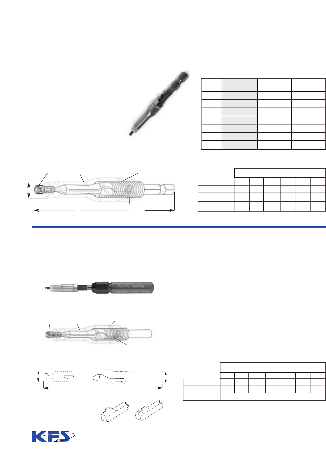
24
Features:
• Lower Cost than current electric
tools and easier to use.
• Designed exclusively for use with
new KFS Electric Driver.
• Hex shank allows for quick-
disconnect.
* KATO recommends Prewinder type
tools for UNF (Fine) thread sizes.
Tangless
®
Hex Shank Insertion Tools
–Unified Sizes
Tangless
®
Hand or Electric Insertion & Removal
Tools, Mandrel Type–Unified Sizes
PAWL HOOK
INSERT DEPTH
ADJUSTING SLEEVE
LOCK NUT
HEX SHANK (Typ.)
“A” Dim. Ref.
“B” Dia.
Hex Size (inch)
2-56
2.85
.250
1/4
4-40
2.95
.250
1/4
6-32
3.05
.375
1/4
8-32
3.20
.375
1/4
10-24
10-32
3.05
.375
1/4
1/4-20
3.05
.375
1/4
Thread Size
Dimensions
Electric Tool Installation Mandrel
Pawl Tip Details
Replacement Pawls
Insertion/Removal Tool Mandrel Assembly
INSTALLATION
REMOVAL
PAWL
HOOK
INSERT DEPTH
ADJUSTING SLEEVE
LOCK NUT
PAWL HOOK
RELEASE
Hand Insertion/Removal Tool
10-32
3.00
.360
“A” Dim. Ref.
“B” Dia. Ref.
2-56
2.80
.250
4-40
2.90
.250
6-32
3.00
.360
8-32
3.15
.360
10-24
3.00
.360
1/4-20
3.00
.360
Thread Size
Shank 0.164 Dia.
Dimensions
Kato recommends Prewinder type tools for the UNF (Fine) thread sizes.
• Hand Insertion and Removal Tools consist of a
mandrel assembly, drive handle, 2 wrenches, and
1 extra pawl, spring, and pin.
• The mandrel assembly can be removed from the drive
handle and used with the Electric Drivers, Part Nos.
CT5405 and CT5406.
• These mandrels cannot be used with the CT5408
Keyless Chuck Electric Driver, since the chuck on this
driver requires a hex shank.
Thread Complete Tool Replacement Replacement
Size Part No. Mandrel Pawl
2-56 2CTSB-02C 2CTSB-02CM 2CTSB-02CP
4-40 2CTSB-04C 2CTSB-04CM 2CTSB-04CP
6-32 2CTSB-06C 2CTSB-06CM 2CTSB-06CP
8-32 2CTSB-2C 2CTSB-2CM 2CTSB-2CP
10-24 2CTSB-3C 2CTSB-3CM 2CTSB-3CP
10-32* 2CTSB-3F 2CTSB-3FM 2CTSB-3FP
1/4-20 2CTSB-4C 2CTSB-4CM 2CTSB-4CP
Hex Shank Mandrel Insertion Tools**
B
PAWL
HOOK
RELEASE
A
B
A
SHANK
**Contact KATO for availability of sizes #10 & 1/4.

25
Tangless
®
Hand or Electric Insertion & Removal
Tools, Mandrel Type–Unified Sizes, continued
Installation Tool Assembly
Removal Tool Assembly
Replacement Pawl Kits
1
Installation
Removal
Replacement Mandrels
Installation
Removal
CT16002-02
CT16002R-02
CT16402-02K
CT16402R-02K
CT16410-02BH
CT16410-02
CT16002-04
CT16002R-04
CT16402-04K
CT16402R-04K
CT16410-04BH
CT16410-04
-
CT16003R-4
-
CT16403R-4K
-
CT16411R-4
CT16002-4
CT16002R-4
CT16402-4K
CT16402R-4K
CT16410-4
CT16410R-4
CT16002-3
CT16002R-3
CT16402-3K
CT16402R-3K
CT16410-3
CT16410R-3
CT16003-3
2
CT16003R-3
CT16403-3K
CT16403R-3K
CT16411-3
CT16411R-3
CT16002-2
CT16002R-2
CT16402-2K
CT16402R-2K
CT16410-2BH
CT16410-2
CT16002-06
CT16002R-06
CT16402-06K
CT16402R-06K
CT16410-06BH
CT16410-06
2-56 4-40 6-32 8-32 10-24 10-32
2
1/4-20 1/4-28
3
Part Numbers
Radial Arm Tool Holder
Part No. CT21042
Notes:
1
Consists of installation or removal pawl, 2 pins and 2 springs.
2
KATO recommends Prewinder type tools for UNF (FINE) thread sizes.
3
The 1/4-28 size installation tool is available in the Prewinder Hand Tool and Air-Driven types only.
4
Please contact KFS for Removal Tools for 5/16 and 3/8 UNC and UNF sizes Tangless Inserts.
Use the Kato Power Tool
with strip feed reels for
vertical installation.
Adapts electric tool
to radial arm.
Adapter Part No.
CT21044A
Complete tool consists of Small or Large Driver, Power Transformer, and Mandrel.
Tool
Small Driver
1
Large Driver
2
Power
Transformer
Part
Number
CT5405
CT5406
CT5407
Length
Ref.
8.6
10.8
4.0
Diameter
Ref.
1.125
1.455
8.0
Chuck
Capacity
5/32
1/4
4.2
Weight
Ref.(lb.)
1
1.8
6
Notes:
1
Small Electric Driver for sizes #2 through #8
2
Large Electric Driver for sizes #10 and 1/4.
Transformer plugs into standard 110 VAC outlet.
Size Ref.
Width Depth Height

26
2TLM - 4x.7C - 6 W SF
Basic Insert Type:
2TNM = Standard, Free-Running,
Metric Tangless Insert
2TLM = Self-Locking, Metric
Tangless Insert
Size Designation (Internal Thread) and Material:
See tabulation on following page. All inserts are
made of Type 304 stainless steel.
Nominal Length (mm):
See tabulation.
Finish:
W = Dry film lubricant per AS5272, Type I
Y = Cadmium plated per QQ-P-416, Type II
(Max. Thickness = .0001”).
No Finish = Leave blank if none is required.
Packaging:
Supplied in bulk or on strip feed reels for power installation.
SF = Strip Feed. Leave blank for bulk.
Bi-directional design eliminates insert
orientation requirement.
Quick, non-destructive removal
prevents damage to castings.
FOD-Free Design: No tangs to break off,
retrieve...or lose.
Cost Reduction: Significantly decreased installa-
tion and inspection time.
Metric Tangless CoilThread Inserts are made of cold-rolled Type
304 stainless steel wire (AS7245 and MA1565), work-hardened
to a tensile strength above 200,000 psi, a hardness of Rc 43-50 and
an exceedingly smooth (8-16 micro-inches) surface finish. Metric
Tangless Inserts are designed to replace tanged helical coil inserts
as specified in MA3279 through MA3281 (standard thread) and
Insert Part Number Selection
Elements to form a complete and specific part number are selected from the table below. Follow the example shown for
proper structure.
Part Number Example:
The example below consists of a Type 304 stainless steel Self-Locking Metric Tangless CoilThread Insert in M4X.7 nominal thread
size, 1-1/2 diameter length, with dry film lubricant finish, supplied on strip feed for power tool installation.
Free-Running Inserts
Self-Locking Inserts
▼
▼
▼
▼
MA3329 through MA3331 (locking thread). They install in stan-
dard STI tapped holes per MA1567. Installed inserts provide a
finished thread meeting the requirements of FED-STD-H28, M
Profile, Tolerance Classes 4H or 5H, as well as ISO metric
thread specifications, and accept standard or MJ profile bolts or
screws.
Tangless CoilThread Inserts
– Metric Sizes
®®
FREE OUTER DIAMETER
INSERT
DRIVING NOTCH
INSERT
INSERT
DRIVING NOTCH
INSERT
DRIVING NOTCH
NUMBER OF FREE COILS
NUMBER OF FREE COILS
FREE OUTER DIAMETER
Material:Type 304 Stainless steel per MA1565 and AS7245
Surface Texture: ASNI B46.1.
Basic Insert Type
Nominal Free- Self-
Thread Running Locking Length of Insert (in Dia.)
3
Size Inserts Inserts 1 11/2 2
M2.5x.45 2TNM 2TLM 2.5 3.8 5
M3x.5 2TNM 2TLM 3 4.5 6
M4x.7 2TNM 2TLM 4 6 8
M5x.8 2TNM 2TLM 5 7.5 10
M6x1 2TNM 2TLM 6 9 12
M8x1.25 2TNM 2TLM 8 12 16
Notes:
1
Nominal length is a calculated number and cannot be measured in the free state. It is the actual installed length plus 1/2 pitch.
2
Number of free coils is the total number of convolutions (counted from notch to notch) and has a tolerance of
±
1/4 coil.
3
Please consult factory for 2-1/2 and 3 Diameter lengths.
Min. Max. 1 11/2 2
3.20 3.35 3.375 5.625 8.000
3.80 3.99 3.750 6.375 8.875
5.05 5.28 3.625 6.125 8.625
6.20 6.50 4.125 6.875 9.625
7.40 7.78 4.000 6.750 9.500
9.80 10.18 4.500 7.375 10.250
Number of Free Coils
2
Nominal Length
Nominal Length (mm)
1
Free Outer
Diameter
(mm)

Tangless
®
CoilThread
®
Inserts Cross Reference
Table – Metric Sizes
Free-Running Series
Nominal Length Tangless CoilThread National Equivalent
Size Length (mm) Insert Aerospace MA
(in Dia.) Part Number Standard Part Number**
Number*
1 2.5 2TNM-2.5x.45C-2.5 * MA3279-101
M2.5x.45 1-1/2 3.8 2TNM-2.5x.45C-3.8 * MA3279-151
252TNM-2.5x.45C-5.0 * MA3279-201
132TNM-3x.5C-3.0 * MA3279-102
M3x.5 1-1/2 4.5 2TNM-3x.5C-4.5 * MA3279-152
262TNM-3x.5C-6.0 * MA3279-202
142TNM-4x.7C-4.0 * MA3279-104
M4x.7 1-1/2 6 2TNM-4x.7C-6.0 * MA3279-154
282TNM-4x.7C-8.0 * MA3279-204
152TNM-5x.8C-5.0 * MA3279-105
M5x.8 1-1/2 7.5 2TNM-5x.8C-7.5 * MA3279-155
2102TNM-5x.8C-10.0 * MA3279-205
162TNM-6x1C-6.0 * MA3279-106
M6x1 1-1/2 9 2TNM-6x1C-9.0 * MA3279-156
2122TNM-6x1C-12.0 * MA3279-206
182TNM-8x1.25C-8.0 * MA3279-109
M8x1.25 1-1/2 12 2TNM-8x1.25C-12.0 * MA3279-159
2162TNM-8x1.25C-16.0 * MA3279-209
Self-Locking Series
1 2.5 2TLM-2.5x.45C-2.5 * MA3329-101
M2.5x.45 1-1/2 3.8 2TLM-2.5x.45C-3.8 * MA3329-151
252TLM-2.5x.45C-5.0 * MA3329-201
132TLM-3x.5C-3.0 * MA3329-102
M3x.5 1-1/2 4.5 2TLM-3x.5C-4.5 * MA3329-152
262TLM-3x.5C-6.0 * MA3329-202
142TLM-4x.7C-4.0 * MA3329-104
M4x.7 1-1/2 6 2TLM-4x.7C-6.0 * MA3329-154
282TLM-4x.7C-8.0 * MA3329-204
152TLM-5x.8C-5.0 * MA3329-105
M5x.8 1-1/2 7.5 2TLM-5x.8C-7.5 * MA3329-155
2102TLM-5x.8C-10.0 * MA3329-205
162TLM-6x1C-6.0 * MA3329-106
M6x1 1-1/2 9 2TLM-6x1C-9.0 * MA3329-156
2122TLM-6x1C-12.0 * MA3329-206
182TLM-8x1.25C-8.0 * MA3329-109
M8x1.25 1-1/2 12 2TLM-8x1.25C-12.0 * MA3329-159
2162TLM-8x1.25C-16.0 * MA3329-209
*Note: At the time of printing of this catalog, NAS part numbers had not been assigned to the Metric Tangless Inserts.
Please contact KFS for further information. **The equivalent MA part number is shown for reference only.
Optional Finishes
Dry Film Lubricant Coating:
Tangless Inserts: Add "W" suffix to Tangless Insert Part No. (see page 26.)
Tanged Inserts, Free-Running use MA3280- part number prefix.
Tanged Inserts, Locking use MA3330- part number prefix.
Cadmium Plating:
Tangless Inserts: Add "Y" suffix to Tangless Insert Part No. (see page 26.)
Tanged Inserts, Free-Running use MA3281- part number prefix.
Tanged Inserts, Locking use MA3331- part number prefix.
27

1. These tools are designed exclusively for use with the new KFS Electric Driver with the
Quick Disconnect Hex Chuck.
2. Metric Inserts have finer threads then their corresponding inch sizes, making them
more difficult to install. Because of this, KFS recommends that Prewinder Type Tools be
used for hand installation, and Air Driven Tools be used with Strip-Feed Inserts for
power installation.
3. Metric Tangless Inserts require a separate Tool be used for Free-Running Inserts, and
Locking Inserts (see table). This applies only to the Hex Shank Insertion Tools.
4. Please contact KFS for technical assistance in choosing the optimum style tool for
installing Metric Tangless Inserts, and for availability of Hex Shank Tool sizes.
28
Part Numbers
Removal Tool
Removal Tool Assembly
M2.5x.45 M3x.5 M4x.7
CT16002R-M2.5 CT16002R-M3 CT16002R-M4
CT16402R-M2.5 CT16402R-M3 CT16402R-M4
Removal Tool Assembly
Replacement Removal Pawl
Tool/Component
Thread Size
Replacement Pawls
• Quick, non-destructive removal of inserts.
• No damage to the tapped threads.
• Can be used to adjust the depth of the installed insert.
Tangless Insert Installation & Removal Tools
– Metric Sizes
®
• Metric threads install easier with Prewinder Tools.
• Steel mandrel and prewinder body.
• Simple to use.
• Reduces insert diameter for smooth and quick installation.
• Maintains alignment of insert throughout installation cycle.
Prewinder Type Hand Installation Tool
Note: Metric size Tangless Removal Tools do not include spare pawl, pin, and spring or wrenches.
Hex Shank Insertion Tool
M5x.8 M6x1 M8x1.25
CT16002R-M5 CT16002R-M6 CT16002R-M8
CT16402R-M5 CT16402R-M6 CT16402R-M8
Free-Running Insert Tool
Locking Insert Tool
Replacement Pawl
M2.5x.45 M3x.5 M4x.7
2CTSB-M2.5F 2CTSB-M3F 2CTSB-M4F 2CTSB-M5F 2CTSB-M6F 2CTSB-M8F
2CTSB-M2.5L 2CTSB-M3L 2CTSB-M4L 2CTSB-M5L 2CTSB-M6L 2CTSB-M8L
2CTSB-M2.5P 2CTSB-M3P 2CTSB-M4P 2CTSB-M5P 2CTSB-M6P 2CTSB-M8P
Thread Size
Hex Shank
Insertion Tool
PAWL
HOOK
INSERT DEPTH
ADJUSTING SLEEVE
LOCK NUT
PAWL HOOK
RELEASE
Complete Tool
Replacement Pawl
M2.5x.45 M3x.5 M4x.7 M5x.8 M6x1 M8x1.25
TCIM-2.5 TCIM-3 TCIM-4 TCIM-5 TCIM-6 TCIM-8
TCIM-2.5P TCIM-3P TCIM-4P TCIM-5P TCIM-6P TCIM-8P
Thread Size
Prewinder Hand
Installation Tool
M5x.8 M6x1 M8x1.25

29
Tangless Insert Air Driven Insertion Tools
– Metric Sizes
®
• Increased productivity.
• No handling of inserts with strip-feed.
• Can be used with HeliCoil
®
brand air motors and adapters.
Front End Assembly Air Motor
Reversible Air Motor with Hose Part Number CT25017
Complete Tool
Prewinder
Plastic Cushion
(Insert into adapter sleeve)
Part Number
CT9605:
M2.5 through
M6
Part Number
CT9705:
M8 and larger
How to Order
Nominal
Thread
Size*
M2.5x.45
M3x.5
M4x.7
M5x.8
M6x1
M8x1.25
Complete
Assembly
2CT11000-M2.5
2CT11000-M3
2CT11000-M4
2CT11000-M5
2CT11000-M6
2CT11000-M8
Replacement
Pawl
2CT11400-M2.5
2CT11400-M3
2CT11400-M4
2CT11400-M5
2CT11400-M6
2CT11400-M8
Example:
for Size M6 Inserts:
COMPLETE TOOL CONSISTS OF:
Air Motor:
Part No. CT25017
Adapter:
Part No. CT9605
Front End Assembly:
Part No. 2CT11000-M6
(Select from Table)
Air Driven Insertion Tool
attached to the KATO Radial
Arm Tool Holder Part No.
CT21042
*Note: The KATO Clutch Drive must
be used with size M2.5 and M3 Front End Assemblies to prevent the
Mandrels from breaking. KFS will not warrantee the Mandrels and Pawls without the use of the Clutch
Drive. KFS recommends Clutch-Drives be used for all size Front End Assemblies to prevent breakage and
to extend the life of the tool.
Air Motor Clutch Drive
with Torque Adjusting
Handle
Note: Clutch Drive fits into the
CT9605 Adapter only.
Tangless
®
Front End Assemblies & Clutch Drive
–Metric Sizes
Replacement
Mandrel
Assembly
2CT11200-M2.5
2CT11200-M3
2CT11200-M4
2CT11200-M5
2CT11200-M6
2CT11200-M8
Metric Size Front End Assemblies*
Air Motor Part No.
CT25017
8510-1
Clutch Drive Part No.
CT9602
CT9602
Air Motor Brand
KATO
®
HeliCoil
®
Mandrel Prewinder
Adapter
Lever
Front-End Assembly (Prewinder & Mandrel)
Air Motor
Adapter
Nut Collar
Pawl
Mandrel Assembly
Spacers
Mandrel
Lever
Hose

30
Tanged CoilThread Inserts and Tools – Unified sizes
• Meet or exceed all applicable military, aerospace and commercial standards.
• Completely interchangeable with all major manufacturers’ inserts and tools.
• Are available in a range of inch and metric sizes, free-running and locking,
and bulk or strip-feed packaging.
Insert Part Number Selection and Identification
How to Order:
Part Number Example:
(Consists of a 304 stainless steel Self-locking CoilThread Insert, in 1/4-20 nominal thread size, 1-1/2 Dia. length, with dry film lubricant finish,
supplied on strip-feed for power installation.)
TLC
- 4C - 0375 W SF
Basic Part Number:
TNC = Standard free-running
CoilThread Insert, Unified Coarse
TNF = Standard free-running
CoilThread Insert, Unified Fine
TLC = Self-locking CoilThread
Insert, Unified Coarse
TLF = Self-locking CoilThread
Insert, Unified Fine
Size Designation (Internal Thread)
and Material:
TNC
TNC
TNC
TNC
TNC
TNC
TNC
TNC
TNC
TNC
TNC
TNC
TNC
TNC
TNC
TNC
TNC
TNC
TLC
TLC
TLC
TLC
TLC
TLC
TLC
TLC
TLC
TLC
TLC
TLC
TLC
TLC
TLC
TLC
TLC
TLC
02C
03C
04C
05C
06C
2C
3C
1C
4C
5C
6C
7C
8C
9C
10C
12C
14C
16C
0.086
0.099
0.112
0.125
0.138
0.164
0.190
0.216
0.250
0.312
0.375
0.438
0.500
0.562
0.625
0.750
0.875
1.000
0.129
0.148
0.168
0.188
0.207
0.246
0.285
0.324
0.375
0.469
0.562
0.656
0.750
0.844
0.938
1.125
1.312
1.500
0.172
0.198
0.224
0.250
0.276
0.328
0.380
0.432
0.500
0.625
0.750
0.875
1.000
1.125
1.250
1.500
1.750
2.000
0.215
0.248
0.280
0.312
0.345
0.410
0.475
0.540
0.625
0.781
0.938
1.094
1.250
1.406
1.562
1.875
2.188
2.500
0.258
0.297
0.336
0.375
0.414
0.492
0.570
0.648
0.750
0.938
1.125
1.312
1.500
1.688
1.875
2.250
2.625
3.000
.110
.128
.144
.158
.178
.205
.244
.270
.310
.380
.452
.526
.597
.669
.742
.881
1.022
1.166
.119
.139
.159
.173
.193
.220
.259
.285
.330
.400
.472
.551
.622
.694
.767
.906
1.052
1.196
3
2-7/8
2-3/4
3-1/4
2-3/4
3-1/2
2-7/8
3-1/2
3-3/8
4
4-3/8
4-1/2
4-7/8
5-1/8
5-1/4
5-7/8
6-1/4
6-3/8
5-1/4
5
4-3/4
5-1/2
4-3/4
6
5
6
5-3/4
6-5/8
7-1/4
7-3/8
7-7/8
8-1/4
8-1/2
9-3/8
10
10-1/8
7-3/8
7-1/4
6-3/4
7-3/4
6-7/8
8-3/8
7-1/8
8-3/8
8
9-1/4
10
10-1/4
11
11-1/2
11-3/4
13
13-3/4
14
9-5/8
9-3/8
8-7/8
10
8-7/8
10-3/4
9-1/4
10-5/8
10-3/8
11-7/8
12-7/8
13-1/8
14-1/8
14-3/4
15
16-1/2
17-1/2
17-3/4
11-7/8
11-1/2
10-7/8
12-1/4
10-7/8
13-1/4
11-3/8
13-1/8
12-3/4
14-5/8
15-3/4
16-1/8
17-1/8
17-7/8
18-3/8
20-1/8
21-1/4
21-5/8
Basic Part
Numbers
Nominal Thread
Size
Size
Designation
Standard
CoilThread
Insert
CoilLock
Insert
Nominal Length
1
Min. Max.
Free Outside
Diameter
Length of Insert (in dia.)
11
1
/2
2
1
/
2
32
11
1
/
2
2
1
/2
32
Nominal Length
Number of Free Coils
2
TNF
TNF
TNF
TNF
TNF
TNF
TNF
TNF
TNF
TNF
TNF
TNF
TNF
TNF
TNF
TLF
TLF
TLF
TLF
TLF
TLF
TLF
TLF
TLF
TLF
TLF
TLF
TLF
TLF
TLF
03C
04C
06C
2C
3C
4C
5C
6C
7C
8C
9C
10C
12C
14C
161C
0.099
0.112
0.138
0.164
0.190
0.250
0.312
0.375
0.438
0.500
0.562
0.625
0.750
0.875
1.000
0.148
0.168
0.207
0.246
0.285
0.375
0.469
0.562
0.656
0.750
0.844
0.938
1.125
1.312
1.500
0.198
0.224
0.276
0.328
0.380
0.500
0.625
0.750
0.875
1.000
1.125
1.250
1.500
1.750
2.000
0.248
0.280
0.345
0.410
0.475
0.625
0.781
0.938
1.094
1.250
1.406
1.562
1.875
2.188
2.500
0.297
0.336
0.414
0.492
0.570
0.750
0.938
1.125
1.312
1.500
1.688
1.875
2.250
2.625
3.000
.131
.147
.173
.204
.236
.306
.380
.448
.524
.592
.666
.733
.876
1.021
1.169
.146
.162
.193
.224
.256
.326
.400
.468
.549
.617
.691
.758
.901
1.051
1.199
3-3/8
3-3/8
3-1/2
3-7/8
4-1/8
5
5-1/2
6-7/8
6-5/8
7-7/8
8
9
9-3/4
9-7/8
9-5/8
5-5/8
5-5/8
6
6-1/2
6-7/8
8-1/4
8-7/8
11
10-5/8
12-3/8
12-1/2
14-1/8
15-1/8
15-1/2
15
8
7-7/8
8-3/8
9-1/8
9-1/2
11-3/8
12-1/4
15
14-5/8
16-7/8
17-1/8
19-1/4
20-5/8
21-1/8
20-1/2
10-3/8
10-1/4
10-3/4
11-5/8
12-1/4
14-1/2
15-5/8
19-1/8
18-1/2
21-3/8
21-3/4
24-1/4
26
26-5/8
26
12-5/8
12-1/2
13-1/4
14-1/4
14-7/8
17-5/8
19
23-1/8
22-1/2
25-7/8
26-1/4
29-3/8
31-1/2
32-1/4
31-1/2
2 (.086)-56
3 (.099)-48
4 (.112)-40
5 (.125)-40
6 (.138)-32
8 (.164)-32
10 (.190)-24
12 (.216)-24
1/4 (.250)-20
5/16 (.3125)-18
3/8(.3750)-16
7/16 (.4375)-14
1/2 (.5000)-13
9/16 (.5625)-12
5/8 (.6250)-11
3/4 (.7500)-10
7/8 (.8750)-9
1 (1.0000)-8
3 (.099)-56
4 (.112)-48
6 (.138)-40
8 (.164)-36
10 (.190)-32
1/4 (.2500)-28
5/16 (.3125)-24
3/8 (.3750)-24
7/16 (.4375)-20
1/2 (.5000)-20
9/16 (.5625)-18
5/8 (.6250)-18
3/4 (.7500)-16
7/8 (.8750)-14
1 (1.0000)-12
Sample Part Number (see full description above)
1
Nominal length is a calculated number and cannot be measured in the free state. It is the actual installed length plus 1/2 pitch.
2
Number of free coils is the total number of convolutions and has a tolerance of ± 1/4 coil. Convolutions are counted by starting 90º from the tang for all fine sizes and for
Coarse sizes 5/8” and smaller. For Coarse sizes 3/4” and up convolutions are counted by starting 180º from the tang.
®
Packaging:
Supplied in bulk or on strip-feed in sizes through 5/16” Dia. for power installation.
SF = Strip-feed. Leave blank for bulk.
Finish:
W = Dry film lubricant
Y = Cadmium plated
Leave blank if none is required
Nominal Length:
See tabulation below. Shown as 4-digit number without the decimal point.
Unified Coarse
Unified Fine

31
TNC-02C-0086
TNC-02C-0129
TNC-02C-0172
TNC-02C-0215
TNC-02C-0258
TNC-03C-0099
TNC-03C-0148
TNC-03C-0198
TNC-03C-0248
TNC-03C-0297
TNC-04C-0112
TNC-04C-0168
TNC-04C-0224
TNC-04C-0280
TNC-04C-0336
TNC-05C-0125
TNC-05C-0188
TNC-05C-0250
TNC-05C-0312
TNC-05C-0375
TNC-06C-0138
TNC-06C-0207
TNC-06C-0276
TNC-06C-0345
TNC-06C-0414
TNC-2C-0164
TNC-2C-0246
TNC-2C-0328
TNC-2C-0410
TNC-2C-0492
TNC-3C-0190
TNC-3C-0285
TNC-3C-0380
TNC-3C-0475
TNC-3C-0570
TNC-1C-0216
TNC-1C-0324
TNC-1C-0432
TNC-1C-0540
TNC-1C-0648
TNC-4C-0250
TNC-4C-0375
TNC-4C-0500
TNC-4C-0625
TNC-4C-0750
TNC-5C-0312
TNC-5C-0469
TNC-5C-0625
TNC-5C-0781
TNC-5C-0938
TNC-6C-0375
TNC-6C-0562
TNC-6C-0750
TNC-6C-0938
TNC-6C-1125
TNC-7C-0438
TNC-7C-0656
TNC-7C-0875
TNC-7C-1094
TNC-7C-1312
TNC-8C-0500
TNC-8C-0750
TNC-8C-1000
TNC-8C-1250
TNC-8C-1500
1185-02CN-0086
1185-02CN-0129
1185-02CN-0172
1185-02CN-0215
1185-02CN-0258
1185-03CN-0099
1185-03CN-0148
1185-03CN-0198
1185-03CN-0248
1185-03CN-0297
1185-04CN-0112
1185-04CN-0168
1185-04CN-0224
1185-04CN-0280
1185-04CN-0336
1185-05CN-0125
1185-05CN-0188
1185-05CN-0250
1185-05CN-0312
1185-05CN-0375
1185-06CN-0138
1185-06CN-0207
1185-06CN-0276
1185-06CN-0345
1185-06CN-0414
1185-2CN-0164
1185-2CN-0246
1185-2CN-0328
1185-2CN-0410
1185-2CN-0492
1185-3CN-0190
1185-3CN-0285
1185-3CN-0380
1185-3CN-0475
1185-3CN-0570
1185-1CN-0216
1185-1CN-0324
1185-1CN-0432
1185-1CN-0540
1185-1CN-0648
1185-4CN-0250
1185-4CN-0375
1185-4CN-0500
1185-4CN-0625
1185-4CN-0750
1185-5CN-0312
1185-5CN-0469
1185-5CN-0625
1185-5CN-0781
1185-5CN-0938
1185-6CN-0375
1185-6CN-0562
1185-6CN-0750
1185-6CN-0938
1185-6CN-1125
1185-7CN-0438
1185-7CN-0656
1185-7CN-0875
1185-7CN-1094
1185-7CN-1312
1185-8CN-0500
1185-8CN-0750
1185-8CN-1000
1185-8CN-1250
1185-8CN-1500
MS122095
MS122135
MS122175
MS122215
MS122255
MS122115
MS122155
MS122195
MS122235
MS122275
MS122076
MS122116
MS122156
MS122196
MS122236
MS122077
MS122117
MS122157
MS122197
MS122237
MS122078
MS122118
MS122158
MS122198
MS122238
MS122079
MS122119
MS122159
MS122199
MS122239
MS122080
MS122120
MS122160
MS122200
MS122240
—
—
—
—
—
MS122081
MS122121
MS122161
MS122201
MS122241
MS122082
MS122122
MS122162
MS122202
MS122242
MS122083
MS122123
MS122163
MS122203
MS122243
MS122084
MS122124
MS122164
MS122204
MS122244
MS122085
MS122125
MS122165
MS122205
MS122245
5340-850-6847
5340-850-6848
5340-834-8372
—
—
5340-111-4194
—
—
—
—
5340-826-4023
5340-842-5290
5340-825-8215
5340-664-4157
5340-660-1513
5340-058-4137
5340-619-3138
5340-928-9816
—
—
5340-843-0003
5340-682-1520
5340-825-4826
5340-200-7755
5340-061-4793
5340-141-6693
5340-297-3841
5340-290-4509
5340-721-7906
5340-291-3479
5340-290-4482
5340-597-3304
5340-290-4478
5340-597-3305
5340-291-3482
5340-969-6086
5340-863-8119
5340-863-8118
—
—
5340-200-7224
5340-290-4481
5340-286-2458
5340-290-4515
5340-290-4489
5340-290-4550
5340-290-4521
5340-290-4520
5340-290-4490
5340-820-9629
5340-290-4519
5340-290-4518
5340-990-7157
5340-290-4492
5340-682-1453
5340-993-7234
5340-290-4506
5340-990-9017
5340-993-7229
5340-993-8194
5340-290-4505
5340-290-4504
5340-990-7158
5340-855-0802
5340-603-0365
1
1-1/2
2
2-1/2
3
1
1-1/2
2
2-1/2
3
1
1-1/2
2
2-1/2
3
1
1-1/2
2
2-1/2
3
1
1-1/2
2
2-1/2
3
1
1-1/2
2
2-1/2
3
1
1-1/2
2
2-1/2
3
1
1-1/2
2
2-1/2
3
1
1-1/2
2
2-1/2
3
1
1-1/2
2
2-1/2
3
1
1-1/2
2
2-1/2
3
1
1-1/2
2
2-1/2
3
1
1-1/2
2
2-1/2
3
.086
.129
.172
.215
.258
.099
.148
.198
.248
.297
.112
.168
.224
.280
.336
.125
.188
.250
.312
.375
.138
.207
.276
.345
.414
.164
.246
.328
.410
.492
.190
.285
.380
.475
.570
.216
.324
.432
.540
.648
.250
.375
.500
.625
.750
.312
.469
.625
.781
.938
.375
.562
.750
.938
1.125
.438
.656
.875
1.094
1.312
.500
.750
1.000
1.250
1.500
2-56
3-48
4-40
5-40
6-32
8-32
10-24
12-24
1/4-20
5/16-18
3/8-16
7/16-14
1/2-13
Size
Length
(In Dia.)
CoilThread
Part Number
Heli-Coil
Part Number
MS
Number
Federal Stock
Number
Length
Cross Reference Table
Free-running Series, UNC

32
Free-running Series, UNC, (continued)
Free-running Series, UNF
TNC-9C-0562
TNC-9C-0844
TNC-9C-1125
TNC-9C-1406
TNC-9C-1688
TNC-10C-0625
TNC-10C-0938
TNC-10C-1250
TNC-10C-1562
TNC-10C-1875
TNC-12C-0750
TNC-12C-1125
TNC-12C-1500
TNC-12C-1875
TNC-12C-2250
TNC-14C-0875
TNC-14C-1312
TNC-14C-1750
TNC-14C-2188
TNC-14C-2625
TNC-16C-1000
TNC-16C-1500
TNC-16C-2000
TNC-16C-2500
TNC-16C-3000
TNC-18C-1125
TNC-18C-1688
TNC-18C-2250
TNC-18C-2812
TNC-18C-3375
TNC-20C-1250
TNC-20C-1875
TNC-20C-2500
TNC-20C-3125
TNC-20C-3750
TNC-22C-1375
TNC-22C-2062
TNC-22C-2750
TNC-22C-3438
TNC-22C-4125
TNC-24C-1500
TNC-24C-2250
TNC-24C-3000
TNC-24C-3750
TNC-24C-4500
1185-9CN-0562
1185-9CN-0844
1185-9CN-1125
1185-9CN-1406
1185-9CN-1688
1185-10CN-0625
1185-10CN-0938
1185-10CN-1250
1185-10CN-1562
1185-10CN-1875
1185-12CN-0750
1185-12CN-1125
1185-12CN-1500
1185-12CN-1875
1185-12CN-2250
1185-14CN-0875
1185-14CN-1312
1185-14CN-1750
1185-14CN-2188
1185-14CN-2625
1185-16CN-1000
1185-16CN-1500
1185-16CN-2000
1185-16CN-2500
1185-16CN-3000
1185-18CN-1125
1185-18CN-1688
1185-18CN-2250
1185-18CN-2812
1185-18CN-3375
1185-20CN-1250
1185-20CN-1875
1185-20CN-2500
1185-20CN-3125
1185-20CN-3750
1185-22CN-1375
1185-22CN-2062
1185-22CN-2750
1185-22CN-3438
1185-22CN-4125
1185-24CN-1500
1185-24CN-2250
1185-24CN-3000
1185-24CN-3750
1185-24CN-4500
MS122086
MS122126
MS122166
MS122206
MS122246
MS122087
MS122127
MS122167
MS122207
MS122247
MS122088
MS122128
MS122168
MS122208
MS122248
MS122089
MS122129
MS122169
MS122209
MS122249
MS122090
MS122130
MS122170
MS122210
MS122250
MS122091
MS122131
MS122171
MS122211
MS122251
MS122092
MS122132
MS122172
MS122212
MS122252
MS122093
MS122133
MS122173
MS122213
MS122253
MS122094
MS122134
MS122174
MS122214
MS122254
5340-993-7237
5340-290-4493
5340-993-7245
5340-726-9499
5340-993-8196
5340-682-1666
5340-290-4494
5340-807-3488
5340-993-7231
5340-816-9381
5340-290-4503
5340-045-2812
5340-721-8356
5340-826-7864
5340-993-8197
5340-993-7236
5340-682-2216
5340-664-8332
5340-993-7232
5340-993-8198
5340-200-2414
5340-530-5603
5340-993-7246
5340-993-7233
5340-993-8199
5340-059-2371
5340-059-2372
5340-059-2373
–
–
5340-059-2374
5340-059-2375
5340-619-8208
–
–
5340-059-2376
5340-059-2377
5340-059-2378
–
–
5340-059-2379
5340-059-2380
5340-059-2381
–
–
1
1-1/2
2
2-1/2
3
1
1-1/2
2
2-1/2
3
1
1-1/2
2
2-1/2
3
1
1-1/2
2
2-1/2
3
1
1-1/2
2
2-1/2
3
1
1-1/2
2
2-1/2
3
1
1-1/2
2
2-1/2
3
1
1-1/2
2
2-1/2
3
1
1-1/2
2
2-1/2
3
.562
.844
1.125
1.406
1.688
.625
.938
1.250
1.562
1.875
.750
1.125
1.500
1.875
2.250
.875
1.312
1.750
2.188
2.625
1.000
1.500
2.000
2.500
3.000
1.125
1.688
2.250
2.812
3.375
1.250
1.875
2.500
3.125
3.750
1.375
2.062
2.750
3.438
4.125
1.500
2.250
3.000
3.750
4.500
9/16-12
5/8-11
3/4-10
7/8-9
1-8
1-1/8-7
1-1/4-7
1-3/8-6
1-1/2-6
Size
Length
(In Dia.)
CoilThread
Part Number
Heli-Coil
Part Number
MS
Number
Federal Stock
Number
Length
TNF-03C-0099
TNF-03C-0148
TNF-03C-0198
TNF-03C-0248
TNF-03C-0297
TNF-04C-0112
TNF-04C-0168
TNF-04C-0224
TNF-04C-0280
TNF-04C-0336
TNF-06C-0138
TNF-06C-0207
TNF-06C-0276
TNF-06C-0345
TNF-06C-0414
TNF-2C-0164
TNF-2C-0246
TNF-2C-0328
TNF-2C-0410
TNF-2C-0492
TNF-3C-0190
TNF-3C-0285
TNF-3C-0380
TNF-3C-0475
TNF-3C-0570
1191-03CN-0099
1191-03CN-0148
1191-03CN-0198
1191-03CN-0248
1191-03CN-0297
1191-04CN-0112
1191-04CN-0168
1191-04CN-0224
1191-04CN-0280
1191-04CN-0336
1191-06CN-0138
1191-06CN-0207
1191-06CN-0276
1191-06CN-0345
1191-06CN-0414
1191-2CN-0164
1191-2CN-0246
1191-2CN-0328
1191-2CN-0410
1191-2CN-0492
1191-3CN-0190
1191-3CN-0285
1191-3CN-0380
1191-3CN-0475
1191-3CN-0570
MS124670
MS124710
MS124750
MS124790
MS124830
MS124671
MS124711
MS124751
MS124791
MS124831
MS124653
MS124693
MS124733
MS124773
MS124813
MS124654
MS124694
MS124734
MS124774
MS124814
MS124655
MS124695
MS124735
MS124775
MS124815
–
–
–
–
–
–
–
–
–
–
5340-045-3553
5340-982-7842
5340-045-3555
5340-726-3547
5340-833-7459
–
5340-097-6337
5340-141-6688
–
5340-833-7457
5340-290-4476
5340-597-3302
5340-290-4480
5340-597-3306
5340-663-3267
1
1-1/2
2
2-1/2
3
1
1-1/2
2
2-1/2
3
1
1-1/2
2
2-1/2
3
1
1-1/2
2
2-1/2
3
1
1-1/2
2
2-1/2
3
.099
.148
.198
.248
.297
.112
.168
.224
.280
.336
.138
.207
.276
.345
.414
.164
.246
.328
.410
.492
.190
.285
.380
.475
.570
3-56
4-48
6-40
8-36
10-32

33
TNF-4C-0250
TNF-4C-0375
TNF-4C-0500
TNF-4C-0625
TNF-4C-0750
TNF-5C-0312
TNF-5C-0469
TNF-5C-0625
TNF-5C-0781
TNF-5C-0938
TNF-6C-0375
TNF-6C-0562
TNF-6C-0750
TNF-6C-0938
TNF-6C-1125
TNF-7C-0438
TNF-7C-0656
TNF-7C-0875
TNF-7C-1094
TNF-7C-1312
TNF-8C-0500
TNF-8C-0750
TNF-8C-1000
TNF-8C-1250
TNF-8C-1500
TNF-9C-0562
TNF-9C-0844
TNF-9C-1125
TNF-9C-1406
TNF-9C-1688
TNF-10C-0625
TNF-10C-0938
TNF-10C-1250
TNF-10C-1562
TNF-10C-1875
TNF-12C-0750
TNF-12C-1125
TNF-12C-1500
TNF-12C-1875
TNF-12C-2250
TNF-14C-0875
TNF-14C-1312
TNF-14C-1750
TNF-14C-2188
TNF-14C-2625
TNF-161C-1000
TNF-161C-1500
TNF-161C-2000
TNF-161C-2500
TNF-161C-3000
TNF-18C-1125
TNF-18C-1688
TNF-18C-2250
TNF-18C-2812
TNF-18C-3375
TNF-20C-1250
TNF-20C-1875
TNF-20C-2500
TNF-20C-3125
TNF-20C-3750
TNF-22C-1375
TNF-22C-2062
TNF-22C-2750
TNF-22C-3438
TNF-22C-4125
TNF-24C-1500
TNF-24C-2250
TNF-24C-3000
TNF-24C-3750
TNF-24C-4500
1191-4CN-0250
1191-4CN-0375
1191-4CN-0500
1191-4CN-0625
1191-4CN-0750
1191-5CN-0312
1191-5CN-0469
1191-5CN-0625
1191-5CN-0781
1191-5CN-0938
1191-6CN-0375
1191-6CN-0562
1191-6CN-0750
1191-6CN-0938
1191-6CN-1125
1191-7CN-0438
1191-7CN-0656
1191-7CN-0875
1191-7CN-1094
1191-7CN-1312
1191-8CN-0500
1191-8CN-0750
1191-8CN-1000
1191-8CN-1250
1191-8CN-1500
1191-9CN-0562
1191-9CN-0844
1191-9CN-1125
1191-9CN-1406
1191-9CN-1688
1191-10CN-0625
1191-10CN-0938
1191-10CN-1250
1191-10CN-1562
1191-10CN-1875
1191-12CN-0750
1191-12CN-1125
1191-12CN-1500
1191-12CN-1875
1191-12CN-2250
1191-14CN-0875
1191-14CN-1312
1191-14CN-1750
1191-14CN-2188
1191-14CN-2625
1191-161CN-1000
1191-161CN-1500
1191-161CN-2000
1191-161CN-2500
1191-161CN-3000
1191-18CN-1125
1191-18CN-1688
1191-18CN-2250
1191-18CN-2812
1191-18CN-3375
1191-20CN-1250
1191-20CN-1875
1191-20CN-2500
1191-20CN-3125
1191-20CN-3750
1191-22CN-1375
1191-22CN-2062
1191-22CN-2750
1191-22CN-3438
1191-22CN-4125
1191-24CN-1500
1191-24CN-2250
1191-24CN-3000
1191-24CN-3750
1191-24CN-4500
MS124656
MS124696
MS124736
MS124776
MS124816
MS124657
MS124697
MS124737
MS124777
MS124817
MS124658
MS124698
MS124738
MS124778
MS124818
MS124659
MS124699
MS124739
MS124779
MS124819
MS124660
MS124700
MS124740
MS124780
MS124820
MS124661
MS124701
MS124741
MS124781
MS124821
MS124662
MS124702
MS124742
MS124782
MS124822
MS124663
MS124703
MS124743
MS124783
MS124823
MS124664
MS124704
MS124744
MS124784
MS124824
MS124651
MS124691
MS124731
MS124771
MS124811
MS124666
MS124706
MS124746
MS124786
MS124826
MS124667
MS124707
MS124747
MS124787
MS124827
MS124668
MS124708
MS124748
MS124788
MS124828
MS124669
MS124709
MS124749
MS124789
MS124829
5340-286-6600
5340-291-3484
5340-290-4497
5340-290-4502
5340-290-4501
5340-290-4660
5340-291-3495
5340-514-2321
5340-680-3131
5340-291-3483
5340-291-3493
5340-291-3492
5340-990-7159
5340-597-3328
5340-291-3491
5340-597-3329
5340-634-7860
5340-290-4511
5340-993-8180
5340-993-7207
5340-598-5634
5340-291-3488
5340-290-4513
5340-290-4507
5340-845-1982
5340-290-5144
5340-291-3487
5340-200-7223
5340-810-9943
5340-291-3486
5340-598-5643
5340-530-7948
5340-597-5157
5340-993-8181
5340-993-7209
5340-141-6710
5340-655-7971
5340-200-7222
5340-993-8182
5340-993-7210
5340-598-5644
5340-045-2848
5340-754-2151
5340-993-8183
5340-993-7211
5340-044-4971
5340-987-9145
5340-044-4970
–
–
5340-598-5599
5340-846-7828
5340-059-2386
–
–
5340-200-4033
5340-558-3435
5340-059-2385
–
–
5340-059-2384
5340-059-2383
5340-059-2382
–
–
5340-836-1941
5340-059-2389
5340-059-2388
–
–
1
1-1/2
2
2-1/2
3
1
1-1/2
2
2-1/2
3
1
1-1/2
2
2-1/2
3
1
1-1/2
2
2-1/2
3
1
1-1/2
2
2-1/2
3
1
1-1/2
2
2-1/2
3
1
1-1/2
2
2-1/2
3
1
1-1/2
2
2-1/2
3
1
1-1/2
2
2-1/2
3
1
1-1/2
2
2-1/2
3
1
1-1/2
2
2-1/2
3
1
1-1/2
2
2-1/2
3
1
1-1/2
2
2-1/2
3
1
1-1/2
2
2-1/2
3
.250
.375
.500
.625
.750
.312
.496
.625
.781
.938
.375
.562
.750
.938
1.125
.438
.656
.875
1.094
1.312
.500
.750
1.000
1.250
1.500
.562
.844
1.125
1.406
1.688
.625
.938
1.250
1.562
1.875
.750
1.125
1.500
1.875
2.250
.875
1.312
1.750
2.188
2.625
1.000
1.500
2.000
2.500
3.000
1.125
1.688
2.250
2.812
3.375
1.250
1.875
2.500
3.125
3.750
1.375
2.062
2.750
3.438
4.125
1.500
2.250
3.000
3.750
4.500
1/4-28
5/16-24
3/8-24
7/16-20
1/2-20
9/16-18
5/8-18
3/4-16
7/8-14
1-12
1-1/8-12
1-1/4-12
1-3/8-12
1-1/2-12
Size
Length
(In Dia.)
CoilThread
Part Number
Heli-Coil
Part Number
MS
Number
Federal Stock
Number
Length
Free-running Series, UNF (continued)

34
TLC-02C-0086
TLC-02C-0129
TLC-02C-0172
TLC-02C-0215
TLC-02C-0258
TLC-03C-0099
TLC-03C-0148
TLC-03C-0198
TLC-03C-0248
TLC-03C-0297
TLC-04C-0112
TLC-04C-0168
TLC-04C-0224
TLC-04C-0280
TLC-04C-0336
TLC-05C-0125
TLC-05C-0188
TLC-05C-0250
TLC-05C-0312
TLC-05C-0375
TLC-06C-0138
TLC-06C-0207
TLC-06C-0276
TLC-06C-0345
TLC-06C-0414
TLC-2C-0164
TLC-2C-0246
TLC-2C-0328
TLC-2C-0410
TLC-2C-0492
TLC-3C-0190
TLC-3C-0285
TLC-3C-0380
TLC-3C-0475
TLC-3C-0570
TLC-1C-0216
TLC-1C-0324
TLC-1C-0432
TLC-1C-0540
TLC-1C-0648
TLC-4C-0250
TLC-4C-0375
TLC-4C-0500
TLC-4C-0625
TLC-4C-0750
TLC-5C-0312
TLC-5C-0469
TLC-5C-0625
TLC-5C-0781
TLC-5C-0938
TLC-6C-0375
TLC-6C-0562
TLC-6C-0750
TLC-6C-0938
TLC-6C-1125
TLC-7C-0438
TLC-7C-0656
TLC-7C-0875
TLC-7C-1094
TLC-7C-1312
TLC-8C-0500
TLC-8C-0750
TLC-8C-1000
TLC-8C-1250
TLC-8C-1500
TLC-9C-0562
TLC-9C-0844
TLC-9C-1125
TLC-9C-1406
TLC-9C-1688
3585-02CN-0086
3585-02CN-0129
3585-02CN-0172
3585-02CN-0215
3585-02CN-0258
3585-03CN-0099
3585-03CN-0148
3585-03CN-0198
3585-03CN-0248
3585-03CN-0297
3585-04CN-0112
3585-04CN-0168
3585-04CN-0224
3585-04CN-0280
3585-04CN-0336
3585-05CN-0125
3585-05CN-0188
3585-05CN-0250
3585-05CN-0312
3585-05CN-0375
3585-06CN-0138
3585-06CN-0207
3585-06CN-0276
3585-06CN-0345
3585-06CN-0414
3585-2CN-0164
3585-2CN-0246
3585-2CN-0328
3585-2CN-0410
3585-2CN-0492
3585-3CN-0190
3585-3CN-0285
3585-3CN-0380
3585-3CN-0475
3585-3CN-0570
3585-1CN-0216
3585-1CN-0324
3585-1CN-0432
3585-1CN-0540
3585-1CN-0648
3585-4CN-0250
3585-4CN-0375
3585-4CN-0500
3585-4CN-0625
3585-4CN-0750
3585-5CN-0312
3585-5CN-0469
3585-5CN-0625
3585-5CN-0781
3585-5CN-0938
3585-6CN-0375
3585-6CN-0562
3585-6CN-0750
3585-6CN-0938
3585-6CN-1125
3585-7CN-0438
3585-7CN-0656
3585-7CN-0875
3585-7CN-1094
3585-7CN-1312
3585-8CN-0500
3585-8CN-0750
3585-8CN-1000
3585-8CN-1250
3585-8CN-1500
3585-9CN-0562
3585-9CN-0844
3585-9CN-1125
3585-9CN-1406
3585-9CN-1688
MS21209-C0210
MS21209-C0215
MS21209-C0220
MS21209-C0225
MS21209-C0230
MS21209-C0310
MS21209-C0315
MS21209-C0320
MS21209-C0325
MS21209-C0330
MS21209-C0410
MS21209-C0415
MS21209-C0420
MS21209-C0425
MS21209-C0430
MS21209-C0510
MS21209-C0515
MS21209-C0520
MS21209-C0525
MS21209-C0530
MS21209-C0610
MS21209-C0615
MS21209-C0620
MS21209-C0625
MS21209-C0630
MS21209-C0810
MS21209-C0815
MS21209-C0820
MS21209-C0825
MS21209-C0830
MS21209-C1-10
MS21209-C1-15
MS21209-C1-20
MS21209-C1-25
MS21209-C1-30
MS21209-C2-10
MS21209-C2-15
MS21209-C2-20
MS21209-C2-25
MS21209-C2-30
MS21209-C4-10
MS21209-C4-15
MS21209-C4-20
MS21209-C4-25
MS21209-C4-30
MS21209-C5-10
MS21209-C5-15
MS21209-C5-20
MS21209-C5-25
MS21209-C5-30
MS21209-C6-10
MS21209-C6-15
MS21209-C6-20
MS21209-C6-25
MS21209-C6-30
MS21209-C7-10
MS21209-C7-15
MS21209-C7-20
MS21209-C7-25
MS21209-C7-30
MS21209-C8-10
MS21209-C8-15
MS21209-C8-20
MS21209-C8-25
MS21209-C8-30
MS21209-C9-10
MS21209-C9-15
MS21209-C9-20
MS21209-C9-25
MS21209-C9-30
5340-855-7892
5340-855-7893
5340-462-4226
___
___
___
5340-886-6312
___
___
___
5340-631-7897
5340-631-7894
5340-827-4024
5340-631-7889
5340-721-7849
___
5340-863-8121
5340-863-8120
___
___
5340-245-5195
5340-815-4930
5340-558-8826
___
___
5340-631-7891
5340-815-4929
5340-721-6936
5340-965-9522
5340-079-9570
___
5340-680-3762
5340-990-8643
___
___
___
5340-863-8116
5340-863-8113
___
___
5340-999-1181
5340-754-0847
5340-721-8352
5340-805-6060
___
5340-685-0926
5340-803-5574
5340-825-6938
___
___
5340-812-1892
5340-754-1976
5340-812-1894
___
___
5340-045-0516
5340-701-3811
5340-723-6775
___
___
5340-834-7050
5340-814-9865
5340-812-1900
___
___
___
5340-987-9146
5340-723-6777
___
___
1
1-1/2
2
2-1/2
3
1
1-1/2
2
2-1/2
3
1
1-1/2
2
2-1/2
3
1
1-1/2
2
2-1/2
3
1
1-1/2
2
2-1/2
3
1
1-1/2
2
2-1/2
3
1
1-1/2
2
2-1/2
3
1
1-1/2
2
2-1/2
3
1
1-1/2
2
2-1/2
3
1
1-1/2
2
2-1/2
3
1
1-1/2
2
2-1/2
3
1
1-1/2
2
2-1/2
3
1
1-1/2
2
2-1/2
3
1
1-1/2
2
2-1/2
3
.086
.129
.172
.215
.258
.099
.148
.198
.248
.297
.112
.168
.224
.280
.336
.125
.188
.250
.312
.375
.138
.207
.276
.345
.414
.164
.246
.328
.410
.492
.190
.285
.380
.475
.570
.216
.324
.432
.540
.648
.250
.375
.500
.625
.750
.312
.496
.625
.781
.938
.375
.562
.750
.938
1.125
.438
.656
.875
1.094
1.312
.500
.750
1.000
1.250
1.500
.562
.844
1.125
1.406
1.688
2-56
3-48
4-40
5-40
6-32
8-32
10-24
12-24
1/4-20
5/16-18
3/8-16
7/16-14
1/2-13
9/16-12
Size
Length
(In Dia.)
CoilThread
Part Number
Heli-Coil
Part Number
MS
Number
Federal Stock
Number
Length
Locking Series, UNC

35
TLC-10C-0625
TLC-10C-0938
TLC-10C-1250
TLC-10C-1562
TLC-10C-1875
TLC-12C-0750
TLC-12C-1125
TLC-12C-1500
TLC-12C-1875
TLC-12C-2250
TLC-14C-0875
TLC-14C-1312
TLC-14C-1750
TLC-14C-2188
TLC-14C-2625
TLC-16C-1000
TLC-16C-1500
TLC-16C-2000
TLC-16C-2500
TLC-16C-3000
TLC-18C-1125
TLC-18C-1688
TLC-18C-2250
TLC-18C-2812
TLC-18C-3375
TLC-20C-1250
TLC-20C-1875
TLC-20C-2500
TLC-20C-3125
TLC-20C-3750
TLC-22C-1375
TLC-22C-2062
TLC-22C-2750
TLC-22C-3438
TLC-22C-4125
TLC-24C-1500
TLC-24C-2250
TLC-24C-3000
TLC-24C-3750
TLC-24C-4500
3585-10CN-0625
3585-10CN-0938
3585-10CN-1250
3585-10CN-1562
3585-10CN-1875
3585-12CN-0750
3585-12CN-1125
3585-12CN-1500
3585-12CN-1875
3585-12CN-2250
3585-14CN-0875
3585-14CN-1312
3585-14CN-1750
3585-14CN-2188
3585-14CN-2625
3585-16CN-1000
3585-16CN-1500
3585-16CN-2000
3585-16CN-2500
3585-16CN-3000
3585-18CN-1125
3585-18CN-1688
3585-18CN-2250
3585-18CN-2812
3585-18CN-3375
3585-20CN-1250
3585-20CN-1875
3585-20CN-2500
3585-20CN-3125
3585-20CN-3750
3585-22CN-1375
3585-22CN-2062
3585-22CN-2750
3585-22CN-3438
3585-22CN-4125
3585-24CN-1500
3585-24CN-2250
3585-24CN-3000
3585-24CN-3750
3585-24CN-4500
MS21209-C1010
MS21209-C1015
MS21209-C1020
MS21209-C1025
MS21209-C1030
MS21209-C1210
MS21209-C1215
MS21209-C1220
MS21209-C1225
MS21209-C1230
MS21209-C1410
MS21209-C1415
MS21209-C1420
MS21209-C1425
MS21209-C1430
MS21209-C1610
MS21209-C1615
MS21209-C1620
MS21209-C1625
MS21209-C1630
MS21209-C1810
MS21209-C1815
MS21209-C1820
MS21209-C1825
MS21209-C1830
MS21209-C2010
MS21209-C2015
MS21209-C2020
MS21209-C2025
MS21209-C2030
MS21209-C2210
MS21209-C2215
MS21209-C2220
MS21209-C2225
MS21209-C2230
MS21209-C2410
MS21209-C2415
MS21209-C2420
MS21209-C2425
MS21209-C2430
5340-772-4849
5340-811-9469
5340-812-1895
5340-753-3497
5340-723-6779
5340-800-1676
5340-724-1921
5340-724-1920
5340-724-1919
5340-993-7232
5340-863--8111
5340-812-1897
5340-956-3008
1
1-1/2
2
2-1/2
3
1
1-1/2
2
2-1/2
3
1
1-1/2
2
2-1/2
3
1
1-1/2
2
2-1/2
3
1
1-1/2
2
2-1/2
3
1
1-1/2
2
2-1/2
3
1
1-1/2
2
2-1/2
3
1
1-1/2
2
2-1/2
3
.625
.938
1.250
1.562
1.875
.750
1.125
1.500
1.875
2.250
.875
1.312
1.750
2.188
2.625
1.000
1.500
2.000
2.500
3.000
1.125
1.688
2.250
2.812
3.375
1.250
1.875
2.500
3.125
3.750
1.375
2.062
2.750
3.438
4.125
1.500
2.250
3.000
3.750
4.500
5/8-11
3/4-10
7/8-9
1-8
1-1/8-7
1-1/4-7
1-3/8-6
1-1/2-6
Size
Length
(In Dia.)
CoilThread
Part Number
Heli-Coil
Part Number
MS
Number
Federal Stock
Number
Length
TLF-03C-0099
TLF-03C-0148
TLF-03C-0198
TLF-03C-0248
TLF-03C-0297
TLF-04C-0112
TLF-04C-0168
TLF-04C-0224
TLF-04C-0280
TLF-04C-0336
TLF-06C-0138
TLF-06C-0207
TLF-06C-0276
TLF-06C-0345
TLF-06C-0414
TLF-2C-0164
TLF-2C-0246
TLF-2C-0328
TLF-2C-0410
TLF-2C-0492
TLF-3C-0190
TLF-3C-0285
TLF-3C-0380
TLF-3C-0475
TLF-3C-0570
3591-03CN-0099
3591-03CN-0148
3591-03CN-0198
3591-03CN-0248
3591-03CN-0297
3591-04CN-0112
3591-04CN-0168
3591-04CN-0224
3591-04CN-0280
3591-04CN-0336
3591-06CN-0138
3591-06CN-0207
3591-06CN-0276
3591-06CN-0345
3591-06CN-0414
3591-2CN-0164
3591-2CN-0246
3591-2CN-0328
3591-2CN-0410
3591-2CN-0492
3591-3CN-0190
3591-3CN-0285
3591-3CN-0380
3591-3CN-0475
3591-3CN-0570
MS21209-F0310
MS21209-F0315
MS21209-F0320
MS21209-F0325
MS21209-F0330
MS21209-F0410
MS21209-F0415
MS21209-F0420
MS21209-F0425
MS21209-F0430
MS21209-F0610
MS21209-F0615
MS21209-F0620
MS21209-F0625
MS21209-F0630
MS21209-F0810
MS21209-F0815
MS21209-F0820
MS21209-F0825
MS21209-F0830
MS21209-F1-10
MS21209-F1-15
MS21209-F1-20
MS21209-F1-25
MS21209-F1-30
5340-754-1207
5340-825-1475
5340-813-2162
5340-684-9501
5340-800-7874
5340-721-7653
1
1-1/2
2
2-1/2
3
1
1-1/2
2
2-1/2
3
1
1-1/2
2
2-1/2
3
1
1-1/2
2
2-1/2
3
1
1-1/2
2
2-1/2
3
.099
.148
.198
.248
.297
.112
.168
.224
.280
.336
.138
.207
.276
.345
.414
.164
.246
.328
.410
.492
.190
.285
.380
.475
.570
3-56
4-48
6-40
8-36
10-32
Locking Series, UNC (continued)
Locking Series, UNF

36
TLF-4C-0250
TLF-4C-0375
TLF-4C-0500
TLF-4C-0625
TLF-4C-0750
TLF-5C-0312
TLF-5C-0469
TLF-5C-0625
TLF-5C-0781
TLF-5C-0938
TLF-6C-0375
TLF-6C-0562
TLF-6C-0750
TLF-6C-0938
TLF-6C-1125
TLF-7C-0438
TLF-7C-0656
TLF-7C-0875
TLF-7C-1094
TLF-7C-1312
TLF-8C-0500
TLF-8C-0750
TLF-8C-1000
TLF-8C-1250
TLF-8C-1500
TLF-9C-0562
TLF-9C-0844
TLF-9C-1125
TLF-9C-1406
TLF-9C-1688
TLF-10C-0625
TLF-10C-0938
TLF-10C-1250
TLF-10C-1562
TLF-10C-1875
TLF-12C-0750
TLF-12C-1125
TLF-12C-1500
TLF-12C-1875
TLF-12C-2250
TLF-14C-0875
TLF-14C-1312
TLF-14C-1750
TLF-14C-2188
TLF-14C-2625
TLF-161C-1000
TLF-161C-1500
TLF-161C-2000
TLF-161C-2500
TLF-161C-3000
TLF-18C-1125
TLF-18C-1688
TLF-18C-2250
TLF-18C-2812
TLF-18C-3375
TLF-20C-1250
TLF-20C-1875
TLF-20C-2500
TLF-20C-3125
TLF-20C-3750
TLF-22C-1375
TLF-22C-2062
TLF-22C-2750
TLF-22C-3438
TLF-22C-4125
TLF-24C-1500
TLF-24C-2250
TLF-24C-3000
TLF-24C-3750
TLF-24C-4500
3591-4CN-0250
3591-4CN-0375
3591-4CN-0500
3591-4CN-0625
3591-4CN-0750
3591-5CN-0312
3591-5CN-0469
3591-5CN-0625
3591-5CN-0781
3591-5CN-0938
3591-6CN-0375
3591-6CN-0562
3591-6CN-0750
3591-6CN-0938
3591-6CN-1125
3591-7CN-0438
3591-7CN-0656
3591-7CN-0875
3591-7CN-1094
3591-7CN-1312
3591-8CN-0500
3591-8CN-0750
3591-8CN-1000
3591-8CN-1250
3591-8CN-1500
3591-9CN-0562
3591-9CN-0844
3591-9CN-1125
3591-9CN-1406
3591-9CN-1688
3591-10CN-0625
3591-10CN-0938
3591-10CN-1250
3591-10CN-1562
3591-10CN-1875
3591-12CN-0750
3591-12CN-1125
3591-12CN-1500
3591-12CN-1875
3591-12CN-2250
3591-14CN-0875
3591-14CN-1312
3591-14CN-1750
3591-14CN-2188
3591-14CN-2625
3591-161CN-1000
3591-161CN-1500
3591-161CN-2000
3591-161CN-2500
3591-161CN-3000
3591-18CN-1125
3591-18CN-1688
3591-18CN-2250
3591-18CN-2812
3591-18CN-3375
3591-20CN-1250
3591-20CN-1875
3591-20CN-2500
3591-20CN-3125
3591-20CN-3750
3591-22CN-1375
3591-22CN-2062
3591-22CN-2750
3591-22CN-3438
3591-22CN-4125
3591-24CN-1500
3591-24CN-2250
3591-24CN-3000
3591-24CN-3750
3591-24CN-4500
MS21209-F4-10
MS21209-F4-15
MS21209-F4-20
MS21209-F4-25
MS21209-F4-30
MS21209-F5-10
MS21209-F5-15
MS21209-F5-20
MS21209-F5-25
MS21209-F5-30
MS21209-F6-10
MS21209-F6-15
MS21209-F6-20
MS21209-F6-25
MS21209-F6-30
MS21209-F7-10
MS21209-F7-15
MS21209-F7-20
MS21209-F7-25
MS21209-F7-30
MS21209-F8-10
MS21209-F8-15
MS21209-F8-20
MS21209-F8-25
MS21209-F8-30
MS21209-F9-10
MS21209-F9-15
MS21209-F9-20
MS21209-F9-25
MS21209-F9-30
MS21209-F1010
MS21209-F1015
MS21209-F1020
MS21209-F1025
MS21209-F1030
MS21209-F1210
MS21209-F1215
MS21209-F1220
MS21209-F1225
MS21209-F1230
MS21209-F1410
MS21209-F1415
MS21209-F1420
MS21209-F1425
MS21209-F1430
MS21209-F1610
MS21209-F1615
MS21209-F1620
MS21209-F1625
MS21209-F1630
MS21209-F1810
MS21209-F1815
MS21209-F1820
MS21209-F1825
MS21209-F1830
MS21209-F2010
MS21209-F2015
MS21209-F2020
MS21209-F2025
MS21209-F2030
MS21209-F2210
MS21209-F2215
MS21209-F2220
MS21209-F2225
MS21209-F2230
MS21209-F2410
MS21209-F2415
MS21209-F2420
MS21209-F2425
MS21209-F2430
5340-805-9658
5340-829-2141
5340-721-7498
5340-410-2476
5340-584-1891
5340-579-3087
5340-847-0734
5340-582-7256
5340-819-2448
5340-079-4983
5340-754-1817
5340-680-8768
5340-678-3311
5340-059-5685
____
5340-716-9148
5340-678-3310
5340-619-4227
5340-067-7814
____
5340-803-7150
5340-678-3309
5340-721-7915
5340-982-7890
____
5340-688-0152
5340-685-0693
5340-726-8526
____
____
5340-815-8338
5340-834-8362
5340-728-9774
____
____
5340-893-1034
5340-723-6780
5340-836-2941
____
____
5340-985-6568
5340-068-1286
5340-721-5110
____
____
5340-045-0528
5340-045-0514
5340-045-0515
____
____
____
____
____
____
____
____
____
____
____
____
____
____
____
____
____
____
____
____
____
____
1
1-1/2
2
2-1/2
3
1
1-1/2
2
2-1/2
3
1
1-1/2
2
2-1/2
3
1
1-1/2
2
2-1/2
3
1
1-1/2
2
2-1/2
3
1
1-1/2
2
2-1/2
3
1
1-1/2
2
2-1/2
3
1
1-1/2
2
2-1/2
3
1
1-1/2
2
2-1/2
3
1
1-1/2
2
2-1/2
3
1
1-1/2
2
2-1/2
3
1
1-1/2
2
2-1/2
3
1
1-1/2
2
2-1/2
3
1
1-1/2
2
2-1/2
3
.250
.375
.500
.625
.750
.312
.469
.625
.781
.938
.375
.562
.750
.938
1.125
.438
.656
.875
1.094
1.312
.500
.750
1.000
1.250
1.500
.562
.844
1.125
1.406
1.688
.625
.938
1.250
1.562
1.875
.750
1.125
1.500
1.875
2.250
.875
1.312
1.750
2.188
2.625
1.000
1.500
2.000
2.500
3.000
1.125
1.688
2.250
2.812
3.375
1.250
1.875
2.500
3.125
3.750
1.375
2.062
2.750
3.438
4.125
1.500
2.250
3.000
3.750
4.500
1/4-28
5/16-24
3/8-24
7/16-20
1/2-20
9/16-18
5/8-18
3/4-16
7/8-14
1-12
1-1/8-12
1-1/4-12
1-3/8-12
1-1/2-12
Size
Length
(In Dia.)
CoilThread
Part Number
Heli-Coil
Part Number
MS
Number
Federal Stock
Number
Length
Locking Series, UNF (continued)
Heli-Coil
®
is a Registered Trademark of Emhart, Inc.

37
KATO Hand Insertion Tools-Unified Sizes
CoilThread Inserts are supplied in both coarse and fine threads. Fine thread
inserts are generally more flexible in the free state than coarse thread inserts.
NOTE: The same tools are used for both free-running and locking inserts.
C DIA
B
DIM
Threaded Mandrel, Style 2
For sizes 9/16” through 1” UNC
A DIM
C DIA
B
DIM
Prewinder, Non-Captive
Sleeve Type, Style 3
For sizes 9/16” through 1” UNF
Prewinder, Captive Sleeve
Type, Style #1
For sizes 2-56 through 1/2” UNC, and for
3-56 through 1/2” UNF
A DIM
C DIA
B
DIM
A DIM
C
Dia.
3/8
3/8
3/8
7/16
7/16
7/16
7/16
1/2
1/2
5/8
11/16
3/4
13/16
5/8
5/8
3/4
7/8
1
3/8
3/8
7/16
7/16
7/16
1/2
5/8
11/16
3/4
13/16
9/16
5/8
3/4
7/8
1
Nominal
Thread
Size
2 (.086)-56
3 (.099)-48
4 (.112)- 40
5 (.125)- 40
6 (.138)- 32
8 (.164)- 32
10 (.190)- 24
12 (.216)- 24
1/4 (.250)- 20
5/16 (.3125)- 18
3/8 (.3750)- 16
7/16 (.4375)- 14
1/2 (.5000)- 13
9/16 (.5625)- 12
5/8 (.6250)- 11
3/4 (.7500)- 10
7/8 (.8750)- 9
1 (1.0000)- 8
3 (.099)- 56
4 (.112)- 48
6 (.138)- 40
8 (.164)- 36
10 (.190)- 32
1/4 (.2500)- 28
5/16 (.3125)- 24
3/8 (.3750)- 24
7/16 (.4375)- 20
1/2 (.5000)- 20
9/16 (.5625)- 18
5/8 (.6250)- 18
3/4 (.7500)- 16
7/8 (.8750)- 14
1 (1.0000)- 12
Tool
Style
1
2
1
3
Tool
Part
Number
CIC-02
CIC-03
CIC-04
CIC-05
CIC-06
CIC-2
CIC-3
CIC-1
CIC-4
CIC-5
CIC-6
CIC-7
CIC-8
CIC-9
CIC-10
CIC-12
CIC-14
CIC-16
CIF-03
CIF-04
CIF-06
CIF-2
CIF-3
CIF-4
CIF-5
CIF-6
CIF-7
CIF-8
CIF-9
CIF-10
CIF-12
CIF-14
CIF-16
B
Dim.
1-3/4
1-3/4
1-3/4
1-3/4
1-3/4
1-3/4
1-3/4
2
2
2-1/2
2-1/2
2-1/2
2-1/2
3-1/2
3-1/2
3-1/2
4
4
1-3/4
1-3/4
1-3/4
1-3/4
1-3/4
2
2-1/2
2-1/2
2-1/2
2-1/2
3-1/2
3-1/2
3-1/2
4
4
A
Dim.
7-5/16
7-5/16
7-5/16
7-5/16
7-5/16
7-5/16
7-5/16
7-7/8
7-7/8
7-21/32
7-15/16
8-19/32
9-1/4
4-7/8
4-7/8
4-7/8
4-7/8
5-1/2
7-5/16
7-5/16
7-5/16
7-5/16
7-5/16
7-7/8
7-21/32
7-15/16
8-19/32
9-1/4
5-3/8
5-5/8
6-13/32
7-5/32
7-15/16
Unified Fine
Unified Coarse
Part Numbers and Dimensions

38
KATO Air Driven Installation Tool
The Air Driven Installation Tool consists of the Air Motor, Adapter, and Front End Assembly. It can be used to
install Tanged or Tangless Inserts, inch or metric sizes. The Front End Assembly is the only component that
changes depending on the thread size, whether the inserts being installed are Tanged or Tangless, and if they
are inch or metric.
A different Front End Assembly is required for each insert thread size.
Features:
• Adjustable for different insert lengths and installation depths.
• Semi-automatic installation.
• Strip feed speeds installation.
• Lightweight; can be used free-hand or with tool holder.
• Compatible with competitors’ inserts and tool components.
The Air Tool can be mounted on the Kato Radial
Arm Tool Holder, Part Number CT21042.
Select KATO Air-Driven Installation Tools to provide
heavy duty service for high volume production runs.
Use vertically mounted in the KATO Power Tool
Holder or freehand at any angle; a complete tool
weighs little more than a pound. Operation is simple
and semi-automatic: light thumb-pressure on a single
lever prewinds and drives inserts into threaded hole:
release of lever automatically retracts mandrel, reset-
ting tool for the next insert.

39
Adapter
**
CT9605
CT9705
CT9605
CT9705
Air Driven Installation Tool
– for Tanged Unified Size Inserts
(Usable with bulk or strip-feed inserts)
Note: For air installation of Tanged Metric, Tangless Unified or Tangless Metric Inserts, see the appropriate
section of the catalog for the selection of the Front End Assemblies needed. The Air Motor and Adapter are
the same for all insert sizes and types. Contact the KATO Tech Group with any questions on power tools.
To Order:
Three separate parts are required to form a complete KATO
Air-Driven Installation Tool. Please request all three part
numbers (listed in shaded columns) when ordering. Part
numbers to order replacement mandrels and prewinders are
also listed in the table below.
Nominal
Thread
Size*
2 (.086)-56
4 (.112)-40
6 (.138)-32
8 (.164)-32
10 (.190)-24
1/4 (.250)-20
5/16(.312)-18
10 (.190)-32
1/4 (.250-28
5/16 (.312)-24
Complete
Assembly
CT11000-02
CT11000-04
CT11000-06
CT11000-2
CT11000-3
CT11000-4
CT11000-5
CT11001-3
CT11001-4
CT11001-5
Replacement
Mandrel
CT11200-02
CT11200-04
CT11200-06
CT11200-2
CT11200-3
CT11200-4
CT11200-5
CT11201-3
CT11201-4
CT11201-5
C
0.09
0.13
0.14
0.15
0.19
0.22
0.26
0.15
0.19
0.22
B
0.32
0.40
0.50
0.51
0.51
0.63
0.75
0.51
0.63
0.75
A DIA.
0.32
0.25
0.32
0.35
0.38
0.42
0.56
0.38
0.43
0.56
Air
Motor
CT25017
CT25017
Replacement
Prewinder
CT11202-02
CT11202-04
CT11202-06
CT11202-2
CT11202-3
CT11202-4
CT11202-5
CT11203-3
CT11203-4
CT11203-5
Front End Assembly – for Tanged Inserts
Front End Assembly
Dimensions
Unified Fine
Unified Coarse
*Contact KATO Tech Group for sizes not shown. **Large adapter, part no. CT9705 required for sizes 5/16 and larger.
Front End Assembly
Adapter (includes Nut Collar)
Air Motor
Nut Collar
Prewinder
Hose (to air supply)
Lever
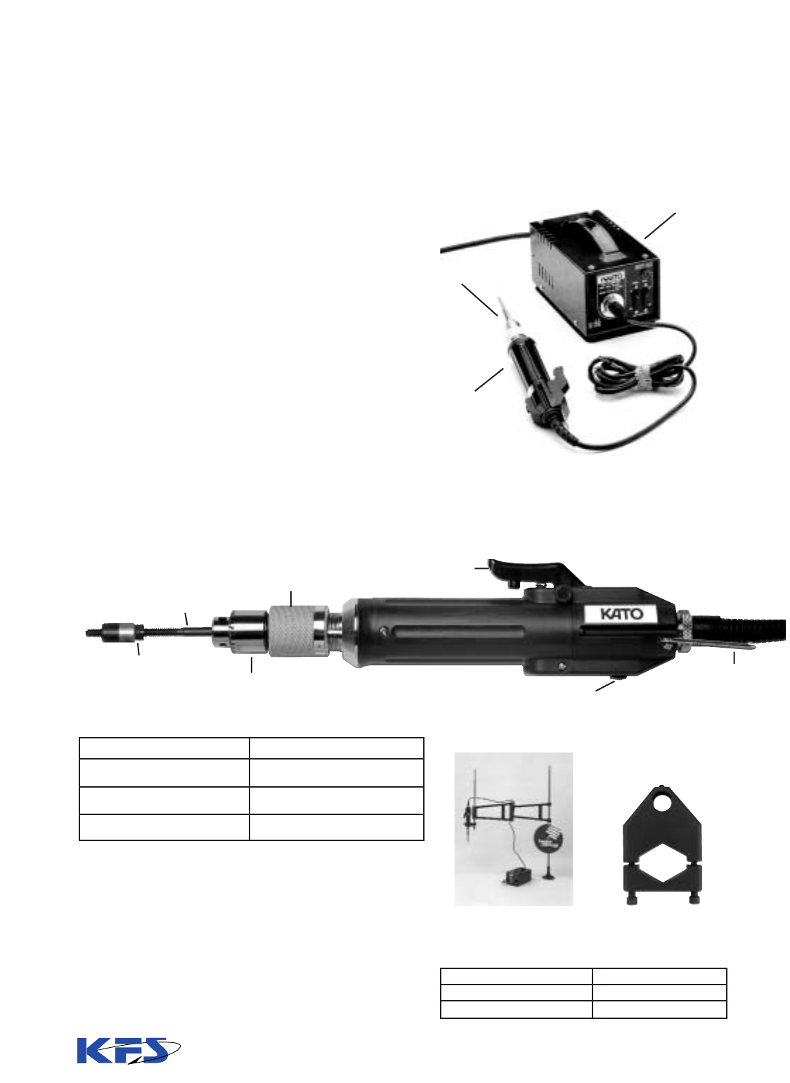
40
Electrically Driven Installation Tools –
for Tanged Unified Size Inserts
This UL-approved electric tool is an alternate to hand
installation where increased production is required.
Ideal for clean room applications, it is lightweight, easy
to use and runs cleanly and quietly. Operates without
operator force and without lubrication. It is also excel-
lent for reaching tapped holes in constricted areas.
Features:
• Tool automatically reverses itself when preset torque
is reached.
• With interchangeable fully-threaded mandrels, tool
installs inserts of varying sizes and lengths.
• Unique design minimizes mandrel wear.
• Knurled control sleeve is rotated quickly and easily to
set required torque (from 0.5 to 4.5 inch-lbs.)
• Installation depth is easy to set. Locks into place
with a stop nut.
• A separate override “forward” and “reverse” switch,
in convenient location at top of tool, assures con-
trolled operation.
Transformer plugs into standard 110VAC outlet.
Transformer
CT21044A
Adapter
Mandrel
Driver
Description
Small Driver:
For Sizes #2 thru #8
Large Driver:
for Sizes 10-24 & 10-32
Transformer
Description
Radial Arm Tool Holder
Adapter for Electric Tool
Part Number
CT21042
CT21044A
Part Numbers
CT5405
CT5406
CT5407
To Order:
Radial Arm Tool Holder
Note
1
: Contact factory for drivers and mandrels
larger than #10 size.
Note
2
: See next page for Electric Tool Mandrel part
numbers and dimensions.
Use the Kato Power Tool with
strip feed reels for vertical
installation.
Adapts electric tool to Kato
or HeliCoil brand radial arm
KNURLED NUT (CONTROL SLEEVE)
IS USED TO SET TORQUE
MANDREL
DEPTH STOP
STANDARD CHUCK
MANUAL OVERRIDE
FORWARD/REVERSE SWITCH
STARTING
SWITCH
BALANCER

41
Dimensions and Operating Instructions:
A
Dia.
Ref.
B
Flats
Ref.
Thread
Size
2-56
4-40
6-32
8-32
10-24
10-32
1/4-20
Mandrel
Part Number
CTSB-02C
CTSB-04C
CTSB-06C
CTSB-2C
CTSB-3C
CTSB-3F
CTSB-4C
Self-Reversing Electrical Driver
.156
.281
.343
.372
.250
.250
Tool
Small Driver
Large Driver
Transformer
Part
Number
CT5405
CT5406
CT5407
Length
Ref.
8.6
10.8
4.0
Diameter
Ref.
1.125
1.455
8.0
Chuck
Capacity
5/32
1/4
4.2
Weight
Ref.(lb.)
1
1.8
6
Torque Adjustment:
1. Reduce torque (by turning knurled sleeve outward)
until insert will not install.
2. Increase torque gradually (by turning knurled sleeve inward)
until insert installs properly. (Do not use higher torque than
necessary to install insert.)
Insert Installation:
Figure 1
Place insert on mandrel with tang firmly engaged on tip.
Figure 2
Figure 3
Installation Instructions
Hold tool in line with tapped hole and install insert, using low
speed setting on transformer.
(Do not force the insert to start into tapped hole.)
Hold switch down until insert is completely installed and mandrel has
withdrawn fully from insert. (Tool will reverse automatically when set
torque has been reached.)
NOTE:
Check for excessive torque if premature tang breakoff or accelerated
mandrel wear is experienced.
If insert does not completely install (hangs up), the tool should be
checked for low torque, or the mandrel should be checked for damaged
or worn tip.
Width Depth Height
Hole Preparation:
1. Locate and drill hole to required depth with drill size specified.
2. Countersink hole.
3. Tap hole (gage hole occasionally to check for tap wear.)
Depth Stop Setting:
1. Back off lock nut from adjusting collar.
2. Place insert firmly on mandrel with tang engaged on tip.
3. Locate adjusting collar to 1 to 1
1
/2 pitches from top
end of insert.
4. Tighten lock nut against adjusting collar.
TORQUE ADJUSTMENT
ADJUSTABLE DEPTH STOP
ALLOWANCE FOR DEPTH OF INSERT
STANDARD CHUCK
Size Ref.
Mandrel Drive Assembly
GUARD
3.00 REF.
LOCK NUT
MANDREL
A DIA.
REF.
B OVER
FLATS
REF
AJUSTING NUT
(COLLAR)

42
Tang Break-off and Insert Extracting Tools –
for Unified Size Tanged Inserts
Nominal
Thread
Size
2 (.086)-56
3 (.099)-48
4 (.112)-40
5 (.125)-40
6 (.138)-32
8 (.164)-32
10 (.190)-24
12 (.216)-24
1/4 (.250)-20
5/16 (.3125)-18
3/8 (.3750)-16
7/16 (.4375)-14
1/2 (5000)-13
3 (.099)-56
4 (.112)-48
6 (.138)-40
8 (.164)- 36
10 (190)- 32
1/4 (.250)- 28
5/16 (.3125)- 24
3/8 (.3750)- 24
7/16 (.4375)- 20
1/2 (.5000)- 20
Tang
Break-Off Tool
Part Number
CAB-02
CAB-02
CAB-04
CAB-04
CAB-06
CAB-2
CAB-3
CAB-3
CAB-4
CAB-5
CAB-6
CAB-7
CAB-8
CAB-02
CAB-04
CAB-06
CAB-2
CAB-3
CAB-4
CAB-5
CAB-6
CAB-7
CAB-8
Insert
Extracting
Tool Part No.
CET-02
CET-06
CET-06
CET-06
CET-06
CET-06
CET-6
CET-6
CET-6
CET-6
CET-6
CET16
CET-16
CET-06
CET-06
CET-06
CET-06
CET-6
CET-6
CET-6
CET-6
CET-16
CET-16
Unified Fine
Unified Coarse
Tang Break-off Tools are for use with 1, 1
1
/2
and 2 diameter
length inserts. For 2
1
/2
and 3 diameter, a separate punch
must be ordered with each tool. To order these sizes, add
-30 to end of part number. Replacement punches can be
ordered by putting an “RP” at the end of the part number.
Example: CAB-02RP.
Use standard needle nose pliers to remove tangs on insert
sizes above 1/2 inch. Bend tang up and down to snap off at
notch.
Extracting Tool Instructions: Apply the tool to installed insert
90˚ from the end. Strike the head of the tool lightly with a
hammer. Turn the tool counterclockwise while maintaining a
steady downward pressure.
Tang Break-off Tool
Insert Extracting tool

43
Metric Tanged CoilThread Inserts
Insert Part Number Selection and Identification
Elements to form a complete and specific part number are selected from the
table below.
Follow the example shown for proper structure.
Part Number Example:
The example below consists of a Type 304 stainless steel Self-locking Metric Tanged CoilThread
Insert in M4x.7 nominal thread size, 1-1/2 Dia. length, with dry film lubricant finish, supplied on strip feed for power installation.
Basic Insert Type:
TNM = Standard free-running
Metric, Tanged Insert
TLM= Self-Locking, Metric
Tanged Insert
Size Designation (Internal Thread)
and Material:
See tabulation on following page. All inserts
are made of Type 304 stainless steel.
Nominal Length (mm):
See tabulation.
Finish:
W = Dry film lubricant per AS5272, Type I.
Y = Cadmium plated per QQ-P-416, Type II.
(Max. Thickness = .0001”).
No Finish = Leave blank if none is required.
Packaging:
Supplied in bulk or on strip feed reels for power installation.
SF = Strip Feed.
Leave blank for bulk.
TLM
- 4x.7C - 6 W SF

44
Insert Dimensions - Metric
TNM
TNM
TNM
TNM
TNM
TNM
TNM
TNM
TNM
TNM
TNM
TNM
TNM
TNM
TNM
TNM
TNM
TLM
TLM
TLM
TLM
TLM
TLM
TLM
TLM
TLM
TLM
TLM
TLM
TLM
TLM
TLM
TLM
TLM
2.2
2.5
3.0
3.5
4.0
5.0
6.0
7.0
8.0
10.0
12.0
14.0
16.0
18.0
20.0
22.0
24.0
3.3
3.8
4.5
6.3
6.0
7.5
9.0
10.5
12.0
15.0
18.0
21.0
24.0
27.0
30.0
33.0
36.0
4.4
5.0
6.0
7.0
8.0
10.0
12.0
14.0
16.0
20.0
24.0
28.0
32.0
36.0
40.0
44.0
48.0
5.5
6.3
7.5
8.8
10.0
12.5
15.0
17.5
20.0
25.0
30.0
35.0
40.0
45.0
50.0
55.0
60.0
6.6
7.5
9.0
10.5
12.0
15.0
18.0
21.0
24.0
30.0
36.0
42.0
48.0
54.0
60.0
66.0
72.0
2.80
3.20
3.80
4.40
5.05
6.25
7.40
8.65
9.80
11.95
14.30
16.65
18.90
21.30
23.55
25.90
28.00
3.00
3.70
4.35
4.95
5.60
6.80
7.95
9.20
10.35
12.50
15.00
17.35
19.60
22.00
24.40
26.90
29.00
3-1/8
3-3/8
3-3/4
3-3/4
3-5/8
4-1/8
4
4-7/8
4-1/2
4-7/8
5
5-1/8
6-1/8
5-3/8
6-1/8
6-3/4
6-1/8
5-3/8
5-3/4
6-3/8
6-3/8
6-1/8
6-7/8
6-3/4
8
7-3/8
8
8-1/4
8-1/2
9-3/4
8-7/8
9-7/8
10-7/8
10
7-5/8
8-1/8
8-7/8
8-3/4
8-5/8
9-5/8
9-1/2
11-1/8
10-1/4
11-1/8
11-1/2
11-3/4
13-1/2
12-1/4
13-5/8
14-7/8
13-3/4
9-7/8
10-1/2
11-3/8
11-3/8
11-1/8
12-3/8
12-1/8
14-1/8
13-1/4
14-1/4
14-5/8
15
17-1/4
15-5/8
17-5/8
19
17-1/2
12-1/8
12-3/4
13-7/8
13-3/4
13-5/8
15-1/8
14-7/8
17-1/8
16-1/8
17-3/8
17-7/8
18-3/8
21
19
21-1/8
23-1/8
21-3/8
Basic Part
Numbers
Nominal
Thread Size
Standard
Non-
Locking
Locking
Nominal Length
1
Min. Max.
Free Outside
Diameter
Length of Insert (in dia.)
11
1
/
2
2
1
/2
32
11
1
/2
2
1
/2
32
Nominal Length
Number of Free Coils
2
TNM
TNM
TNM
TNM
TNM
TNM
TNM
TNM
TNM
TNM
TNM
TNM
TNM
TNM
TLM
TLM
TLM
TLM
TLM
TLM
TLM
TLM
TLM
TLM
TLM
TLM
TLM
TLM
8.0
10.0
10.0
12.0
12.0
14.0
16.0
18.0
20.0
22.0
18.0
20.0
22.0
24.0
12.0
15.0
15.0
18.0
18.0
21.0
24.0
27.0
30.0
33.0
27.0
30.0
33.0
36.0
16.0
20.0
20.0
24.0
24.0
28.0
32.0
36.0
40.0
44.0
36.0
40.0
44.0
48.0
20.0
25.0
25.0
30.0
30.0
35.0
40.0
45.0
50.0
55.0
45.0
50.0
55.0
60.0
24.0
30.0
30.0
36.0
36.0
42.0
48.0
54.0
60.0
66.0
54.0
60.0
66.0
72.0
9.70
11.95
12.10
14.30
14.25
16.55
18.90
21.05
23.15
25.55
21.15
23.20
25.60
28.10
10.25
12.50
12.65
15.00
14.95
17.25
19.60
21.75
24.00
26.45
21.85
24.05
26.50
29.10
5-7/8
7-5/8
5-7/8
7-1/4
6
7-1/8
8-1/4
9-1/2
10-3/4
11-7/8
7
7-7/8
8-3/4
9-1/2
9-3/8
12
9-1/2
11-5/8
9-5/8
11-3/8
13-1/8
15
16-7/8
18-1/2
11-1/8
12-1/2
13-3/4
15
13
16-1/2
13-1/8
15-7/8
13-3/8
15-5/8
18
20-3/8
22-7/8
25-1/8
15-3/8
17-1/4
18-7/8
20-3/8
16-1/2
21
16-3/4
20-1/4
17
20
22-3/4
25-7/8
28-7/8
31-5/8
19-1/2
21-7/8
23-7/8
25-7/8
20-1/8
25-1/2
20-3/8
24-1/2
20-3/4
24-1/4
27-5/8
31-3/8
35
38-1/4
23-5/8
26-1/2
29
31-1/4
M2.2x0.45
M2.5x0.45
M3x0.5
M3.5x0.6
M4x0.7
M5x0.8
M6x1
M7x1
M8x1.25
M10x1.5
M12x1.75
M14x2
M16x2
M18x2.5
M20x2.5
M22x2.5
M24x3
M8X1
M10x1
M10x1.25
M12x1.25
M12x1.5
M14x1.5
M16x1.5
M18x1.5
M20x1.5
M22x1.5
M18x2
M20x2
M22x2
M24x2
Metric Fine Series
1
Nominal Length is a calculated number and cannot be measured in the free state. It is the actual installed length
plus 1/2 pitch.
2
Number of Free Coils are counted 90° from the tang.
Metric Coarse Series

45
2.2
3.3
4.4
5.5
6.6
2.5
3.8
5.0
6.3
7.5
3.0
4.5
6.0
7.5
9.0
3.5
5.3
7.0
8.8
10.5
4.0
6.0
8.0
10.0
12.0
5.0
7.5
10.0
12.5
15.0
6.0
9.0
12.0
15.0
18.0
7.0
10.5
14.0
17.5
21.0
8.0
12.0
16.0
20.0
24.0
8.0
12.0
16.0
20.0
24.0
10.0
15.0
20.0
25.0
30.0
10.0
15.0
20.0
25.0
30.0
10.0
15.0
20.0
25.0
30.0
TNM-2.2x.45C-2.2
TNM-2.2x.45C-3.3
TNM-2.2x.45C-4.4
TNM-2.2x.45C-5.5
TNM-2.2x.45C-6.6
TNM-2.5x.45C-2.5
TNM-2.5x.45C-3.8
TNM-2.5x.45C-5.0
TNM-2.5x.45C-6.3
TNM-2.5x.45C-7.5
TNM-3x.5C-3.0
TNM-3x.5C-4.5
TNM-3x.5C-6.0
TNM-3x.5C-7.5
TNM-3x.5C-9.0
TNM-3.5x.6C-3.5
TNM-3.5x.6C-5.3
TNM-3.5x.6C-7.0
TNM-3.5x.6C-8.8
TNM-3.5x.6C-10.5
TNM-4x.7C-4.0
TNM-4x.7C-6.0
TNM-4x.7C-8.0
TNM-4x.7C-10.0
TNM-4x.7C-12.0
TNM-5x.8C-5.0
TNM-5x.8C-7.5
TNM-5x.8C-10.0
TNM-5x.8C-12.5
TNM-5x.8C-15.0
TNM-6x1C-6.0
TNM-6x1C-9.0
TNM-6x1C-12.0
TNM-6x1C-15.0
TNM-6x1C-18.0
TNM-7x1C-7.0
TNM-7x1C-10.5
TNM-7x1C-14.0
TNM-7x1C-17.5
TNM-7x1C-21.0
TNM-8x1C-8.0
TNM-8x1C-12.0
TNM-8x1C-16.0
TNM-8x1C-20.0
TNM-8x1C-24.0
TNM-8x1.25C-8.0
TNM-8x1.25C-12.0
TNM-8x1.25C-16.0
TNM-8x1.25C-20.0
TNM-8x1.25C-24.0
TNM-10x1C-10.0
TNM-10x1C-15.0
TNM-10x1C-20.0
TNM-10x1C-25.0
TNM-10x1C-30.0
TNM-10x1.25C-10.0
TNM-10x1.25C-15.0
TNM-10x1.25C-20.0
TNM-10x1.25C-25.0
TNM-10x1.25C-30.0
TNM-10x1.5C-10.0
TNM-10x1.5C-15.0
TNM-10x1.5C-20.0
TNM-10x1.5C-25.0
TNM-10x1.5C-30.0
1084-2.2CN-2.2
1084-2.2CN-3.3
1084-2.2CN-4.4
1084-2.2CN-5.5
1084-2.2CN-6.6
1084-2.5CN-2.5
1084-2.5CN-3.8
1084-2.5CN-5.0
1084-2.5CN-6.3
1084-2.5CN-7.5
1084-3CN-3.0
1084-3CN-4.5
1084-3CN-6.0
1084-3CN-7.5
1084-3CN-9.0
1084-3.5CN-3.5
1084-3.5CN-5.3
1084-3.5CN-7.0
1084-3.5CN-8.8
1084-3.5CN-10.5
1084-4CN-4.0
1084-4CN-6.0
1084-4CN-8.0
1084-4CN-10.0
1084-4CN-12.0
1048-5CN-5.0
1084-5CN-7.5
1084-5CN-10.0
1084-5CN12.5
1084-5CN-15.0
1084-6CN-6.0
1084-6CN-9.0
1084-6CN-12.0
1084-6CN-15.0
1084-6CN-18.0
1084-7CN-7.0
1084-7CN-10.5
1084-7CN-14.0
1084-7CN-17.5
1084-7CN-21.0
4255-8CN-8.0
4255-8CN-12.0
4255-8CN-16.0
4255-8CN-20.0
4255-8CN-24.0
1084-8CN-8.0
1084-8CN-12.0
1084-8CN-16.0
1084-8CN-20.0
1084-8CN-24.0
4255-10CN-10.0
4255-10CN-15.0
4255-10CN-20.0
4255-10CN-25.0
4255-10CN-30.0
4649-10CN-10.0
4649-10CN-15.0
4649-10CN-20.0
4649-10CN-25.0
4649-10CN-30.0
1084-10CN-10.0
1084-10CN-15.0
1084-10CN-20.0
1084-10CN-25.0
1084-10CN-30.0
MA3279-100
MA3279-150
MA3279-200
MA3279-250
MA3279-300
MA3279-101
MA3279-151
MA3279-201
MA3279-251
MA3279-301
MA3279-102
MA3279152
MA3279-202
MA3279-252
MA3279-302
MA3279-103
MA3279-153
MA3279-203
MA3279-253
MA3279-303
MA3279-104
MA3279-154
MA3279-204
MA3279-254
MA3279-304
MA3279-105
MA3279-155
MA3279-205
MA3279-255
MA3279-305
MA3279-106
MA3279-156
MA3279-206
MA3279-256
MA3279-306
MA3279-107
MA3279-157
MA3279-207
MA3279-257
MA3279-307
MA3279-108
MA3279-158
MA3279-208
MA3279-258
MA3279-308
MA3279-109
MA3279-159
MA3279-209
MA3279-259
MA3279-309
__
__
__
__
__
MA3279-110
MA3279-160
MA3279-210
MA3279-260
MA3279-310
MA3279-111
MA3279-161
MA3279-211
MA3279-261
MA3279-311
1
1-1/2
2
2-1/2
3
1
1-1/2
2
2-1/2
3
1
1-1/2
2
2-1/2
3
1
1-1/2
2
2-1/2
3
1
1-1/2
2
2-1/2
3
1
1-1/2
2
2-1/2
3
1
1-1/2
2
2-1/2
3
1
1-1/2
2
2-1/2
3
1
1-1/2
2
2-1/2
3
1
1-1/2
2
2-1/2
3
1
1-1/2
2
2-1/2
3
1
1-1/2
2
2-1/2
3
1
1-1/2
2
2-1/2
3
.086
.129
.172
.215
.258
.098
.148
.197
.246
.295
.118
.177
.236
.295
.354
.138
.209
.276
.344
.413
.157
.236
.315
.394
.472
.197
.295
.394
.492
.590
.236
.354
.472
.590
.709
.276
.413
.551
.689
.827
.315
.472
.630
.787
.945
.315
.472
.630
.787
.945
.394
.590
.787
.984
1.181
.394
.590
.787
.984
1.181
.394
.590
.787
.984
1.181
M2.2x0.45
M2.5x0.45
M3x0.5
M3.5x0.6
M4x0.7
M5x0.8
M6x1
M7x1
M8x1
M8x1.25
M10x1
M10x1.25
M10x1.5
Size
Length
(In Dia.)
CoilThread
Part Number
Heli-Coil
Part Number
MA
Number
Length
Inch
MM
Metric, Free-running Series
Cross Reference Table

46
12.0
18.0
24.0
30.0
36.0
12.0
18.0
24.0
30.0
36.0
12.0
18.0
24.0
30.0
36.0
TNM-12x1.25C-12.0
TNM-12x1.25C-18.0
TNM-12x1.25C-24.0
TNM-12x1.25C-30.0
TNM-12x1.25C-36.0
TNM-12x1.5C-12.0
TNM-12x1.5C-18.0
TNM-12x1.5C-24.0
TNM-12x1.5C-30.0
TNM-12x1.5C-36.0
TNM-12x1.75C-12.0
TNM-12x1.75C-18.0
TNM-12x1.75C-24.0
TNM-12x1.75C-30.0
TNM-12x1.75C-36.0
4649-12CN-12.0
4649-12CN-18.0
4649-12CN-24.0
4649-12CN-30.0
4649-12CN-36.0
3745-12CN-12.0
3745-12CN-18.0
3745-12CN-24.0
3745-12CN-30.0
3745-12CN-36.0
1084-12CN-12.0
1084-12CN-18.0
1084-12CN-24.0
1084-12CN-30.0
1084-12CN-36.0
MA3279-112
MA3279-162
MA3279-212
MA3279-262
MA3279-312
MA3279-113
MA3279-163
MA3279-213
MA3279-263
MA3279-313
MA3279-114
MA3279-164
MA3279-214
MA3279-264
MA3279-314
1
1-1/2
2
2-1/2
3
1
1-1/2
2
2-1/2
3
1
1-1/2
2
2-1/2
3
.472
.709
.945
1.181
1.417
.472
.709
.945
1.181
1.417
.472
.709
.945
1.181
1.417
Size
Length
(In Dia.)
CoilThread
Part Number
Heli-Coil
Part Number
MA
Number
Length
Inch
MM
Metric, Free-running Series (continued)
2.2
3.3
4.4
5.5
6.6
2.5
3.8
5.0
6.3
7.5
3.0
4.5
6.0
7.5
9.0
3.5
5.3
7.0
8.8
10.0
4.0
6.0
8.0
10.0
12.0
5.0
7.5
10.0
12.5
15.0
6.0
9.0
12.0
15.0
18.0
7.0
10.5
14.0
17.5
21.0
TLM-2.2x.45C-2.2
TLM-2.2x.45C-3.3
TLM-2.2x.45C-4.4
TLM-2.2x.45C-5.5
TLM-2.2x.45C-6.6
TLM-2.5x.45C-2.5
TLM-2.5x.45C-3.8
TLM-2.5x.45C-5.0
TLM-2.5x.45C-6.3
TLM-2.5x.45C-7.5
TLM-3x.5C-3.0
TLM-3x.5C-4.5
TLM-3x.5C-6.0
TLM-3x.5C-7.5
TLM-3x.5C-9.0
TLM-3.5x.6C-3.5
TLM-3.5x.6C-5.3
TLM-3.5x.6C-7.0
TLM-3.5x.6C-8.8
TLM-3.5x.6C-10.5
TLM-4x.7C-4.0
TLM-4x.7C-6.0
TLM-4x.7C-8.0
TLM-4x.7C-10.0
TLM-4x.7C-12.0
TLM-5x.8C-5.0
TLM-5x.8C-7.5
TLM-5x.8C-10.0
TLM-5x.8C-12.5
TLM-5x.8C-15.0
TLM-6x1C-6.0
TLM-6x1C-9.0
TLM-6x1C-12.0
TLM-6x1C-15.0
TLM-6x1C-18.0
TLM-7x1C-7.0
TLM-7x1C-10.5
TLM-7x1C-14.0
TLM-7x1C-17.5
TLM-7x1C-21.0
4184-2.2CN-2.2
4184-2.2CN-3.3
4184-2.2CN-4.4
4184-2.2CN-5.5
4184-2.2CN-6.6
4184-2.5CN-2.5
4184-2.5CN-3.8
4184-2.5CN-5.0
4184-2.5CN-6.3
4184-2.5CN-7.5
4184-3CN-3.0
4184-3CN-4.5
4184-3CN-6.0
4184-3CN-7.5
4184-3CN-9.0
4184-3.5CN-3.5
4184-3.5CN-5.3
4184-3.5CN-7.0
4184-3.5CN-8.8
4184-3.5CN-10.5
4184-4CN-4.0
4184-4CN-6.0
4184-4CN-8.0
4184-4CN-10.0
4184-4CN-12.0
4184-5CN-5.0
4184-5CN-7.5
4184-5CN-10.0
4184-5CN-12.5
4184-5CN-15.0
4184-6CN-6.0
4184-6CN-9.0
4184-6CN-12.0
4184-6CN-15.0
4184-6CN-18.0
4184-7CN-7.0
4184-7CN-10.5
4184-7CN-14.0
4184-7CN-17.5
4184-7CN-21.0
MA3329-100
MA3329-150
MA3329-200
MA3329-250
MA3329-300
MA3329-101
MA3329-151
MA3329-201
MA3329-251
MA3329-301
MA3329-102
MA3329-152
MA3329-202
MA3329-252
MA3329-302
MA3329-103
MA3329-153
MA3329-203
MA3329-253
MA3329-303
MA3329-104
MA3329-154
MA3329-204
MA3329-254
MA3329-304
MA3329-105
MA3329-155
MA3329-205
MA3329-255
MA3329-305
MA3329-106
MA3329-156
MA3329-206
MA3329-256
MA3329-306
MA3329-107
MA3329-157
MA3329-207
MA3329-257
MA3329-307
1
1-1/2
2
2-1/2
3
1
1-1/2
2
2-1/2
3
1
1-1/2
2
2-1/2
3
1
1-1/2
2
2-1/2
3
1
1-1/2
2
2-1/2
3
1
1-1/2
2
2-1/2
3
1
1-1/2
2
2-1/2
3
1
1-1/2
2
2-1/2
3
.086
.129
.172
.215
.258
.098
.148
.197
.246
.295
.118
.177
.236
.295
.354
.138
.209
.276
.344
.413
.157
.236
.315
.394
.472
.197
.295
.394
.492
.590
.236
.354
.472
.590
.709
.276
.413
.551
.689
.827
M2.2x0.45
M2.5x0.45
M3x0.5
M3.5x0.6
M4x0.7
M5x0.8
M6x1
M7x1
Size
Length
(In Dia.)
CoilThread
Part Number
Heli-Coil
Part Number
MA
Number
Length
Inch
MM
Metric, Locking Series
M12x1.25
M12x1.5
M12x1.75

47
8.0
12.0
16.0
20.0
24.0
8.0
12.0
16.0
20.0
24.0
10.0
15.0
20.0
25.0
30.0
10.0
15.0
20.0
25.0
30.0
10.0
15.0
20.0
25.0
30.0
12.0
18.0
24.0
30.0
36.0
12.0
18.0
24.0
30.0
36.0
12.0
18.0
24.0
30.0
36.0
TLM-8x1C-8.0
TLM-8x1C-12.0
TLM-8x1C-16.0
TLM-8x1C-20.0
TLM-8x1C-24.0
TLM-8x1.25C-8.0
TLM-8x1.25C-12.0
TLM-8x1.25C-16.0
TLM-8x1.25C-20.0
TLM-8x1.25C-24.0
TLM-10x1C-10.0
TLM-10x1C-15.0
TLM-10x1C-20.0
TLM-10x1C-25.0
TLM-10x1C-30.0
TLM-10x1.25C-10.0
TLM-10x1.25C-15.0
TLM-10x1.25C-20.0
TLM-10x1.25C-25.0
TLM-10x1.25C-30.0
TLM-10x1.5C-10.0
TLM-10x1.5C-15.0
TLM-10x1.5C-20.0
TLM-10x1.5C-25.0
TLM-10x1.5C-30.0
TLM-12x1.25C-12.0
TLM-12x1.25C-18.0
TLM-12x1.25C-24.0
TLM-12x1.25C-30.0
TLM-12x1.25C-36.0
TLM-12x1.5C-12.0
TLM-12x1.5C-18.0
TLM-12x1.5C-24.0
TLM-12x1.5C-30.0
TLM-12x1.5C-36.0
TLM-12x1.75C-12.0
TLM-12x1.75C-18.0
TLM-12x1.75C-24.0
TLM-12x1.75C-30.0
TLM-12x1.75C-36.0
5255-8CN-8.0
5255-8CN-12.0
5255-8CN-16.0
5255-8CN-20.0
5255-8CN-24.0
4184-8CN-8.0
4184-8CN-12.0
4184-8CN-16.0
4184-8CN-20.0
4184-8CN-24.0
5255-10CN-10.0
5255-10CN-15.0
5255-10CN-20.0
5255-10CN-25.0
5255-10CN-30.0
5649-10CN-10.0
5649-10CN-15.0
5649-10CN-20.0
5649-10CN-25.0
5649-10CN-30.0
4184-10CN-10.0
4184-10CN-15.0
4184-10CN-20.0
4184-10CN-25.0
4184-10CN-30.0
5649-12CN-12.0
5649-12CN-18.0
5649-12CN-24.0
5649-12CN-30.0
5649-12CN-36.0
5145-12CN-12.0
5145-12CN-18.0
5145-12CN-24.0
5145-12CN-30.0
5145-12CN-36.0
4184-12CN-12.0
4184-12CN-18.0
4184-12CN-24.0
4184-12CN-30.0
4184-12CN-36.0
MA3329-108
MA3329-158
MA3329-208
MA3329-258
MA3329-308
MA3329-109
MA3329-159
MA3329-209
MA3329-259
MA3329-309
__
__
__
__
__
MA3329-110
MA3329-160
MA3329-210
MA3329-260
MA3329-310
MA3329-111
MA3329-161
MA3329-211
MA3329-261
MA3329-311
MA3329-112
MA3329-162
MA3329-212
MA3329-262
MA3329-312
MA3329-113
MA3329-163
MA3329-213
MA3329-263
MA3329-313
MA3329-114
MA3329-164
MA3329-214
MA3329-264
MA3329-314
1
1-1/2
2
2-1/2
3
1
1-1/2
2
2-1/2
3
1
1-1/2
2
2-1/2
3
1
1-1/2
2
2-1/2
3
1
1-1/2
2
2-1/2
3
1
1-1/2
2
2-1/2
3
1
1-1/2
2
2-1/2
3
1
1-1/2
2
2-1/2
3
.315
.472
.630
.787
.945
.315
.472
.630
.787
.945
.394
.590
.787
.984
1.181
.394
.590
.787
.984
1.181
.394
.590
.787
.984
1.181
.472
.709
.945
1.181
1.417
.472
.709
.945
1.181
1.417
.472
.709
.945
1.181
1.417
M8x1
M8x1.25
M10x1
M10x1.25
M10x1.5
M12x1.25
M12x1.5
M12x1.75
Size
Length
(In Dia.)
CoilThread
Part Number
Heli-Coil
Part Number
MA
Number
Length
Inch
MM
Metric, Locking Series (continued)
Heli-Coil
®
is a Registered Trademark of Emhart, Inc.

48
Nominal Thread Size Hand Inserting Tool Style
M2.2X0.45 CIM-2.2
M2.5X0.45 CIM-2.5
M3X0.5 CIM-3
M3.5X0.6 CIM-3.5
M4X0.7 CIM-4
M5X0.8 CIM-5
M6X1 CIM-6
M7X1 CIM-7
M8X1.25 CIM-8X1.25
M10X1.5 CIM-10X1.5
M12X1.75 CIM-12X1.75
M14X2 CIM-14X2
M16X2 CIM-16X2
M18X2.5 CIM-18X2.5
M20X2 CIM-20X2
M8X1 CIM-8X1
M10X1 CIM-10X1
M10X1.25 CIM-10X1.25
M12X1.25 CIM-12X1.25
M12X1.5 CIM-12X1.5
M14X1.5 CIM-14X1.5
M14X1.25 CIM-14X1.25
M16X1.5 CIM-16X1.5
M18X1.5 CIM-18X1.5
Hand Inserting Tools for Metric Size Tanged Inserts
Coarse
Fine
1
3
1
3
Prewinder Type, Style #1
Sizes M2.2 through M12
Non-captive Prewinder, Style #3
Sizes M14 and larger
Tool
Style
Hand Inserting Tool
Part Number
NOTE: The same tools are used for both free-running and locking inserts.

Metric Size Front End Assemblies Power Components
M2.5X0.45 CT11000-M2.5 CT11200-M2.5 CT11202-M2.5
M3X0.5 CT11000-M3 CT11200-M3 CT11202-M3
M4X0.7 CT11000-M4 CT11200-M4 CT11202-M4
M5X0.8 CT11000-M5 CT11200-M5 CT11202-M5
M6X1 CT11000-M6 CT11200-M6 CT11202-M6
M8X1.25 CT11000-M8 CT11200-M8 CT11202-M8
49
Air-Driven Insertion Tools – for Tanged Metric Inserts
Electrically-Driven Installation Tools – for Tanged Metric Inserts*
Complete
Assembly
Nominal
Thread Size
Replacement
Mandrel
Replacement
Prewinder
Adapter
Air Motor
M2.5X0.45 CTSB-M2.5
M3X0.5 CTSB-M3
M4X0.7 CTSB-M4
M5X0.8 CTSB-M5
M6X1 CTSB-M6
M8X1.25
Contact factory for availability.
Mandrel
Assembly
Electric Driver
Transformer
Nominal
Thread Size
CT5405
CT5406
Front End Assembly
Adapter (Includes Nut collar)
Radial arm tool holder P/N CT21042
Complete Electric Tool
Bracket P/N 21044A adapts electric tool to
KATO or HeliCoil brand radial arms
CT9605
CT9705
CT25017
Note: Contact factory for sizes above M8.
CT5407
Air Motor
Nut Collar
Prewinder
Hose (to air supply)
Lever
small
large
*Complete tool consists of Small or Large Electric Driver, Mandrel Assembly, and Transformer.

50
Tang Break-off Tool
Insert ExtractingTool
Tang Break-off and Insert Extracting Tools –
for Tanged Metric Inserts
Nominal Thread Size Tang Break-off Tool Insert Extracting Tool
Part Number Part Number*
M2.2X0.45 CAB-02 CET-02
M2.5X0.45 CAB-02 CET-02
M3X0.5 CAB-04 CET-06
M3.5X0.6 CAB-06 CET-06
M4X0.7 CAB-2 CET-06
M5X0.8 CAB-3 CET-6
M6X1 CAB-4 CET-6
M7X1 CAB-4 CET-6
M8X1.25 CAB-5 CET-6
M10X1.5 CAB-6 CET-6
M12X1.75 CAB-8 CET-16
M8X1 CAB-5 CET-6
M10X1 CAB-6 CET-6
M10X1.25 CAB-6 CET-6
M12X1.25 CAB-8 CET-16
M12X1.5 CAB-8 CET-16
Note: For sizes 14 mm and up, use long-nosed pliers.
Bend tang up and down to snap off at notch.
Extracting Tool Instructions:
Apply tool to installed insert 90° from the end. Strike the head of the tool lightly with a hammer.
Turn tool counterclockwise while maintaining a steady downward pressure.
*Sizes M14 thru M24 use CET-16.
Fine
Coarse

TM
- Thread Repair Kits
Screw Thread Inserts for Maintenance, Repair and Overhaul
Thread repair using CoilThread
®
Inserts is a universally accepted method of repairing stripped threads in all types of
metals. Damaged threads can be brought back to the original thread size, and be better than new using stainless steel
inserts. Thread wear, corrosion and galling will be virtually eliminated, and the assembly will be stronger than the
original with CoilThread
®
.
Unlike threaded solid bushing type fasteners, CoilThread
®
Inserts provide space and weight savings to your repair
process. In addition, they eliminate the need for oversized drilling and tapping, and welding or plugging of damaged
holes. At Kato, there is only one standard of quality for original equipment or repair inserts - All CoilThread
®
Inserts
meet or exceed all applicable military, aerospace and commercial standards.
Each individual thread size Kato-Kit
comes with the following:
•
Quantity of Tanged Free-Running Inserts
in the (1 1/2 Diameter)
most popular length.
• Proper Drill to be used with the STI (screw thread insert) tap*.
• STI Tap for the thread size to be repaired.
• Inserting Tool.
•
Complete and foolproof Instructions
.
*Drills are included in kits up to and including sizes 1/4 inch and M6.
INDIVIDUAL THREAD REPAIR KITS – INCH and METRIC SIZES:
INCH COARSE (UNC) THREAD REPAIR KITS
KIT Contents and Replacement Parts
4-40 x .168 CTKK-04C 12 CTKT-04C CTKI-04C 5 CTKP-04C 12 #31
5-40 x .188 CTKK-05C 12 CTKT-05C CTKI-05C 5 CTKP-05C 12 #29
6-32 x .207 CTKK-06C 12 CTKT-06C CTKI-06C 5 CTKP-06C 12 #25
8-32 x .246 CTKK-2C 12 CTKT-2C CTKI-2C 5 CTKP-2C 12 11/64
10-24 x .285 CTKK-3C 12 CTKT-3C CTKI-3C 5 CTKP-3C 12 13/64
12-24 x .324 CTKK-1C 12 CTKT-1C CTKI-1C 5 CTKP-1C 12 15/64
1/4-20 x .375 CTKK-4C 12 CTKT-4C CTKI-4C 5 CTKP-4C 12 17/64
5/16-18 x .469 CTKK-5C 12 CTKT-5C CTKI-5C 5 CTKP-5C 12 21/64
3/8-16 x .562 CTKK-6C 12 CTKT-6C CTKI-6C 5 CTKP-6C 12 25/64
7/16-14 x .656 CTKK-7C 12 CTKT-7C CTKI-7C 5 CTKP-7C 12 29/64
1/2-13 x .750 CTKK-8C 12 CTKT-8C CTKI-8C 5 CTKP-8C 12 17/32
9/16-12 x .844 CTKK-9C 6 CTKT-9C CTKI -9C 5 CTKP-9C 6 19/32
5/8-11 x .938 CTKK-10C 6 CTKT-10C CTKI-10C 5 CTKP-10C 6 21/32
3/4-10 x 1.125 CTKK-12C 4 CTKT-12C CTKI-12C 5 CTKP-12C 4 25/32
7/8-9 x 1.312 CTKK-14C 4 CTKT-14C CTKI-14C 5 CTKP-14C 4 29/32
1-8 x 1.500 CTKK-16C 4 CTKT-16C CTKI-16C 5 CTKP-16C 4 1-1/32
1 1/8-7 x 1.688 CTKK-18C 4 CTKT-18C CTKI-18C 3 CTKP-18C 4 1-5/32
1 1/4-7 x 1.875 CTKK-20C 4 CTKT-20C CTKI-20C 3 CTKP-20C 4 1-9.32
1 3/8-6 x 2.062 CTKK-22C 4 CTKT-22C CTKI-22C 3 CTKP-22C 4 1-13/32
1 1/2-6 x 2.250 CTKK-24C 4 CTKT-24C CTKI-24C 3 CTKP-24C 4 1-17/32
51
Thread Size &
Length
KatoKit
Part No.
Inserts
per
Kit
Tap
Part No.
Inserting Tool
Part No.
Tool
Style
*
Insert
Replacement
Pack P/N
Insert
Qty/ Pack
Drill
Size

6-40 x .207 CTKK-06F 12 CTKT-06F CTKI-06F 2 CTKP-06F 12 #25
8-36 x .246 CTKK-2F 12 CTKT-2F CTKI-2F 2 CTKP-2F 12 #17
10-32 x .285 CTKK-3F 12 CTKT-3F CTKI-3F 6 CTKP-3F 12 13/64
1/4-28 x .375 CTKK-4F 12 CTKT-4F CTKI-4F 6 CTKP-4F 12 17/64
5/16-24 x .469 CTKK-5F 12 CTKT-5F CTKI-5F 6 CTKP-5F 12 21/64
3/8-24 x .562 CTKK-6F 12 CTKT-6F CTKI-6F 6 CTKP-6F 12 25/64
7/16-20 x .656 CTKK-7F 12 CTKT-7F CTKI-7F 6 CTKP-7F 12 29/64
1/2-20 x .750 CTKK-8F 12 CTKT-8F CTKI-8F 6 CTKP-8F 12 33/64
9/16-18 x .844 CTKK-9F 6 CTKT-9F CTKI-9F 6 CTKP-9F 6 37/64
5/8-18 x .938 CTKK-10F 6 CTKT-10F CTKI-10F 6 CTKP-10F 6 41/64
3/4-16 x 1.125 CTKK-12F 4 CTKT-12F CTKI-12F 6 CTKP-12F 4 49/64
7/8-14 x 1.312 CTKK-14F 4 CTKT-14F CTKI-14F 4 CTKP-14F 4 57/64
1-14 x 1.500 CTKK-16F 4 CTKT-16F CTKI-16F 4 CTKP-16F 4 1-1/64
1-12 x 1.500 CTKK-161 4 CTKT-161 CTKI-161 4 CTKP-161 4 1-1/64
1 1/8-12 x 1.688 CTKK-18F 4 CTKT-18F CTKI-18F 4 CTKP-18F 4 1-5/32
1 1/4-12 x 1.875 CTKK-20F 4 CTKT-20F CTKI-20F 4 CTKP-20F 4 1-9/32
1 3/8-12 x 2.062 CTKK-22F 4 CTKT-22F CTKI-22F 4 CTKP-22F 4 1-13/32
1 1/2-12 x 2.250 CTKK-24F 4 CTKT-24F CTKI-24F 4 CTKP-24F 4 1-17/32
METRIC COARSE THREAD REPAIR KITS
KIT Contents and Replacement Parts
M3x0.5 CTKK-M3 12 CTKT-M3 CTKI-M3 6 CTKP-M3 12 1/8
M3.5x0.6 CTKK-M3.5 12 CTKT-M3.5 CTKI-M3.5 2 CTKP-M3.5 12 #27
M4x0.7 CTKK-M4 12 CTKT-M4 CTKI-M4 6 CTKP-M4 12 11/64
M5x0.8 CTKK-M5 12 CTKT-M5 CTKI-M5 6 CTKP-M5 12 13/64
M6x1 CTKK-M6 12 CTKT-M6 CTKI-M6 6 CTKP-M6 12 1/4
M7x1 CTKK-M7 12 CTKT-M7 CTKI-M7 5 CTKP-M7 12 9/32
M8x1.25 CTKK-M8x1.25 12 CTKT-M8x1.25 CTKI-M8x1.25 5 CTKP-M8x1.25 12 21/64
M10x1.5 CTKK-M10x1.5 12 CTKT-M10x1.5 CTKI-M10x1.5 5 CTKP-M10x1.5 12 13/32
M12x1.75 CTKK-M12x1.75 12 CTKT-M12x1.75 CTKI-M12x1.75 5 CTKP-M12x1.75 12 31/64
M14x2 CTKK-M14x2 12 CTKT-M14x2 CTKI-M14x2 5 CTKP-M14x2 12 37/64
M16x2 CTKK-M16x2 6 CTKT-M16x2 CTKI-M16x2 5 CTKP-M16x2 6 21/32
M18x2.5 CTKK-M18x2.5 6 CTKT-M18x2.5 CTKI-M18x2.5 5 CTKP-M18x2.5 4 47/64
M20x2.5 CTKK-M20x2.5 4 CTKT-M20x2.5 CTKI-M20x2.5 5 CTKP-M20x2.5 4 13/16
52
4
Thread Size &
Length
KatoKit
Part No.
Inserts
per
Kit
Tap
Part No.
Inserting Tool
Part No.
Tool
Style
*
Insert
Replacement
Pack P/N
Insert
Qty/
Pack
Drill
Size
Thread Size &
Length
KatoKit
Part No.
Inserts
per
Kit
Tap
Part No.
*Contact Kato for Tool Style.
Inserting Tool
Part No.
Tool
Style
*
Insert
Replacement
Pack P/N
Insert
Qty/
Pack
Drill
Size
INCH FINE (UNF) THREAD REPAIR KITS
KIT Contents and Replacement Parts

53
METRIC FINE THREAD REPAIR KITS
KIT Contents and Replacement Parts
M8x1 CTKK-M8x1 12 CTKT-M8x1 CTKI-M8x1 6 CTKP-M8x1 12 21/64
M10x1 CTKK-M10x1 12 CTKT-M10x1 CTKI-M10x1 6 CTKP-M10x1 12 13/32
M10x1.25 CTKK-M10x1.25 12 CTKT-M10x1.25 CTKI-M10x1.25 6 CTKP-M10x1.25 12 13/32
M12x1.25 CTKK-M12x1.25 12 CTKT-M12x1.25 CTKI-M12x1.25 6 CTKP-M12x1.25 12 31/64
M12x1.5 CTKK-M12x1.5 12 CTKT-M12x1.5 CTKI-M12x1.5 6 CTKP-M12x1.5 12 31/64
M14x1.5 CTKK-M14x1.5 12 CTKT-M14x1.5 CTKI-M14x1.5 6 CTKP-M14x1.5 12 9/16
M16x1.5 CTKK-M16x1.5 6 CTKT-M16x1.5 CTKI-M16x1.5 6 CTKP-M16x1.5 6 21/3
M18x1.5 CTKK-M18x1.5 6 CTKT-M18x1.5 CTKI-M18x1.5 6 CTKP-M18x1.5 6 47/64
Custom Master Thread Repair Sets:
• Create your own custom set with the range of sizes you use most frequently.
• Available in inch or metric sizes, or a combination of both.
• Packaged in one convenient, attractive box.
• Reduced cost – no need to buy sizes that you do not need.
• Each kit contains the necessary drills, taps, inserts, inserting tools and instructions.
Pipe Thread Repair Kits:
• Available in 1/8-27 through 1 –11
1
/
2
NPT sizes.
• Each kit contains inserts, drill, tap, inserting tool and instructions.
• Contact factory for availability and technical assistance.
Spark Plug Repair Kits:
• Available in 10 mm through 18 mm, and 7/8 – 18 spark plug sizes.
• Do not use to repair taper seat spark plug ports.
• Do not use in aircraft engine repairs.
• Each kit contains inserts, drill, tap, inserting tool and instructions.
• Contact factory for availability and technical assistance.
Special Applications Kits:
• Contact factory for availability of thread repair kits that are not shown,
or for special applications.
Thread Size &
Length
KatoKit
Part No.
Inserts
per Kit
Tap
Part No.
Inserting Tool
Part No.
Tool
Style
Insert
Replacement
Pack P/N
Insert
Qty/
Pack
Drill
Size

54
Torque vs. Temperature
Conventional spring type hinges can lose their
lubrication and seize up to damage mating parts
if used in high temperature environments, or
where excessive cycling increases the tempera-
ture inside the hinge. The HEXATORQ design, uti-
lizing a modern engineered plastic resin, requires
no lubrication. In fact, in an elevated temperature
application, HEXATORQ hinges experience a pre-
dictable drop-off in torque, and will then return to
preset torque values after a minimal cool down
period. This means no damage to your expensive
parts!
• Smooth Operation
• Consistent torque over life—designed for 30,000 cycles or more without failure
• High durability—virtually unaffected by wear
• Holds position throughout full range of motion—no spring-back
• Lightweight and compact—maximized space and weight savings
• Standardized design—six torque ranges and several mounting configurations
• Corrosion resistant stainless steel and engineered resin construction
• Hex configuration provides for easy mold-in mounting without brackets
• FOD-free design—no metal-to-metal friction means no foreign object damage
from metal particles
• No lubrication required—eliminates the possibility of contamination or corrosion
to sensitive parts
KATO
®
HEXATORQ
™
torque controlling hinges now set the industry standard for reliable,
cost effective motion control. Hexatorq
™
hinges are innovative, high quality metal and
plastic resin hinge assemblies that offer an unprecedented smoothness of motion. They
are offered in standardized sizes to meet virtually all common application requirements.
We’ve done the testing for you! Our standardized range of HEXATORQ
™
sizes and con-
figurations was determined through extensive design and durability testing. By utiliz-
ing a HEXATORQ
™
series hinge you can significantly reduce your typical design to
manufacture time cycle. Add those savings right to your bottom line!
Applications
• Notebook/Laptop Computers • Cabinets/Enclosures • Access Panels
• Medical/Laboratory Equipment • Office Equipment/Computer Peripherals
• Covers/Equipment Guards
• Automotive/Aerospace
• Access & Motion Control
Torque vs. Cycle Life
HEXATORQ
™
The Smooth Operator of Constant Torque
Hinges
Typical Performance
™

55
Use the following formula:
T = W x D x Cos (A)
Where: A = Angle
D = Distance to Center of Gravity
T = Torque
W = Weight of Object to be Supported
Example: W = 2 lbs. D = 4 in. A = 0°
T = (2) (4) Cos (0°)
T=8 lbf - in
Note: If two hinges are used: 8/2=4lbf-in
Dimensions and Specifications
Ordering
Part number example: the example below consists of a KATO
®
HEXATORQ™ hinge with a torque
rating of 50 kgf-mm, with bracket, righthand mounting, with a shaft diameter of 5.0 mm and 2
holes in the shaft.
D
A
W
KH52B050R
™
Non-Bracketed
Bracketed
Lefthand mounting shown.
Notes: 1. All dimensions in millimeters (mm).
2. To convert torque from kgf-mm to lbf-in, multiply by 0.0868.
Type:
KH = KATO
®
hinge
Shaft Diameter (mm):
5.0, 6.0 or 7.0
Mounting (Bracket Type Only):
L = Lefthand
R = Righthand
Number of Shaft Holes:
1 or 2
Style:
A = without bracket
B = with bracket (Requires Mounting Suffix)
Torque Rating (kgf-mm):
25, 50, 75, 100, 125 or 150
[
*
]
Style designator; see ordering information below.
Calculating Torque Requirements
Torque Bracket Type Without Bracket
Model No. kgf-mm lbf-in A (REF) B C E a b c ØD Ød Øf t
KH51[
*
]025
25 2.2 11.2 9.8 1.5 9.0 9.3 8.2 4.8 7.0 5.0 2.7 2.0
KH52[
*
]025
KH51[
*
]050
50 4.3 11.2 9.8 1.5 9.0 9.3 8.2 4.8 7.0 5.0 2.7 2.0
KH52[
*
]050
KH61[
*
]075
75 6.5 13.4 11.8 2.0 10.0 11.6 10.2 5.8 8.1 6.0 3.2 2.5
KH62[
*
]075
KH61[
*
]100
100 8.7 13.4 11 .8 2.0 10.0 11.6 10.2 5.8 8.1 6.0 3.2 2.5
KH62[
*
]100
KH71[
*
]125
125 10.9 16.1 14.2 2.5 11.0 14.0 12.2 7.0 10.2 7.0 3.2 3.0
KH72[
*
]125
KH71[
*
]150
150 13.0 16.1 14.2 2.5 11.0 14.0 12.2 7.0 10.2 7.0 3.2 3.0
KH72[
*
]150

Tangless
®
and Tanged Tooling Guide
New! You asked for it, and now it’s here. Everything you wanted to know about installation tools
for Tangless and Tanged Inserts. The Guide includes hand tools, power tools (air and electric), not to men-
tion taps, gages, tang break-off, and removal tools. The dimensions for the various tools are included for your
reference, as well as the replacement parts that you might need. And, we have included interchangeable part
number lists for our competitors’ tools. The Guide is your best single source for all of your tooling needs, and
by far the most comprehensive manual for helical coil insert tooling in the industry. Would you expect anything
less from the company that brought you Tangless® Inserts and Tools?
The new tooling guide is available on our website www.katonet.com. Just log on and fill out the request form,
and a link will be emailed to you, giving you access to the Guide in Adobe® PDF, or Word doc formats.
Need Technical Help?
Visit our website at www.katonet.com, email the Kato Tech Group at [email protected], or call us at
(757) 873-8980.
KATO Fastening News™ is our on-line technical newsletter covering Tangless and Tanged Inserts and Tools,
and their applications. See the inside back cover of this catalog for a list of tech subjects available for reference,
and also how to subscribe to KATO Fastening News™.
56

KATO
®
Fastening News
™
– Subscribe Now!
Kato Fastening News™, our on-line newsletter is published six times per year and jam-packed with technical information, help-
ful hints, and updates on new products. To view the tech articles go to our website, www.katonet.com, click on Tech Info and
then Technical News Letter. To subscribe, go to our website and fill out the Technical Newsletter, On Line Form.
Kato Fastening Systems’ website www.katonet.com is considered to be the most comprehensive site worldwide for technical
information on helical coil inserts and tools, and their applications. Listed below are the tech subjects published on our website
at the time of the printing of this catalog:
Tech Article Subject Date Published
• Using Thread Locking & Sealing Compounds May–June 1997
• Tangs - To Break or Not to Break May–June 1998
• Galling Protection July–Aug 1998
• Magnetic Permeability Nov–Dec 1998
• Torque for Dummies Jan–Feb 1999
• Drilling & Tapping March–April 1999
• Insert Retention -Tangless vs. Tanged Inserts May–June 1999
• Threads, Threads & “J” Threads July–Aug 1999
• New 4-40 Tangless Air Tool Sept–Oct 1999
• Insert Assembly Tensile Strength Nov–Dec 1999
• Locking Inserts - Do’s, Don’ts, and FAQ’s Answered March–April 2000
• Corrosion Problems in Fastener Applications May–June 2000
• Ingersoll-Rand
®
(ARO) Air Motor July–Aug 2000
• Air Tool Trouble Shooting Guide Sept–Oct 2000
• Prewinder Tools - Everything You Wanted to Know… Nov–Dec 2000
• CoilThread-R™ - Removable Tanged Insert May–June 2001
• Spiralock
®
vs. Locking Helical Coil Inserts July–Aug 2001
• Tangless Installation Tooling Life Sept–Oct 2001
• Insert Retention - Tangless vs. Tanged (No Difference!) Nov–Dec 2001
• Resin-Bonded Fluoropolymer Coating on Inserts Jan–Feb 2002
• KATO-KITS™ Line of Thread Repair Kits March–April 2002
• New Metric Tangless
®
Hand Installation Tools May–June 2002
• The Science Behind Pitch Diameter and Class of Fit July–Aug 2002
• Platings and Coatings on CoilThread
®
Inserts Sept–Oct 2002
• Thread Forming Taps for STI Tapped Holes Nov–Dec 2002
• New Tangless Sizes - 5/16” & 3/8” UNC & UNF Jan–Feb 2003
• Drilling and Tapping Depth in Limited Thickness Material March–April 2003
If you have a technical question, please call us, or email us at [email protected].
Kato Tech Group = T
3
(T
hink Tomorrow Today!)
Visit us online at www.katonet.com
KATO Fastening Systems, Inc. • 11836 Fishing Point Drive, Suite 400 • Newport News, VA 23606
Phone: 757-873-8980 • Fax: 757-873-4920 • www.katonet.com
INSERTS & TOOLS
A member of the ADVANEX Group
Tangless
®
AND Tanged
