
www.asahi-america.com
Engineering
Design Guide
Single Wall Piping x Double Wall Piping xGas & Air Handling Systems
xMaterials xSystem Design x Installation
www.asahi-america.com

ENGINEERING
DESIGN
GUIDE
ASAHI/AMERICA, INC.
Lawrence, Massachusetts

Disclaimer
Asahi/America, Inc. provides this guide to assist engineers in the design of
systems, installers in the installation and owners in the operation. This guide
is designed to provide the best possible recommendations known at the
WLPHRISULQWLQJ(DFKDQGHYHU\W\SHRISLSLQJV\VWHPLVGLႇHUHQWDQGQRRQH
recommendation can cover all conditions. This guide is made available to
assist in the design and installation, but in no way should be construed as a
written recommendation on any system. Each system should be individually
designed and installed based on the responsibility and decisions of the
purchaser. This guide is not a substitute for contacting Asahi/America for
VSHFL¿F UHFRPPHQGDWLRQV RQ D V\VWHP ,Q DGGLWLRQ $VDKL$PHULFD LV QRW
responsible for items not appearing in the guide or recommendations that
may have changed after the printing of this guide. It is recommended in each
FDVHWRFRQVXOW$VDKL$PHULFDIRUVSHFL¿FUHFRPPHQGDWLRQVRQHDFKV\VWHP
Copyright © 2013 Asahi/America, Inc. All rights reserved. Printed in USA.

ABOUT THE COMPANY
Asahi/America, Inc. a wholly-owned subsidiary of Asahi Organic Chemical,
pioneered the market for thermoplastic valves and piping in the United States
and Latin America, during a time when there was no viable alternative to
metal for piping systems. Asahi/America began by promoting valves from a
company known as Asahi Organic Chemical Industry Co., Ltd. (AOC) and piping
through AGRU GmbH in Austria. Through distributor and end user education
and acceptance, the use of thermoplastics has grown. Asahi/America now
manufactures and distributes thermoplastic products including valves, actuators,
single and double wall piping systems and specialty components throughout the
US and Latin America.
$VDKL$PHULFDLVDGLYHUVL¿HG,62FHUWL¿HGPDQXIDFWXUHUDQG
VXSSOLHURIFRUURVLRQUHVLVWDQWÀXLGÀRZSURGXFWV+HDGTXDUWHUHGLQ/DZUHQFH
0DVVDFKXVHWWVZKHUHZHRSHUDWHDVTXDUHIRRWPDQXIDFWXULQJDQG
warehouse facility, Asahi/America supports all of our products with a
comprehensive selection of in-depth technical documents and product
catalogs. To access any of Asahi/America’s technical documentation, testing
information, or product catalogs, visit the company’s website at
www.asahi-america.com or contact customer service at 1-800-343-3618.
What makes Asahi/America special is our ability to provide solutions for
FRUURVLYHRUKLJKSXULW\ÀXLGKDQGOLQJV\VWHPVLQGLYLGXDOL]HGWRPHHWYLUWXDOO\
DQ\FXVWRPHU¶VQHHG7KH$VDKL$PHULFDWHFKQLFDOVWDႇLVDEOHWRSURYLGH
superior knowledge of products, applications and installations. Asahi/America is
poised to support your next project with the assistance of our large distribution
network.
Asahi/America is proud to present this Engineering Design Guide to you. This
publication represents over 40 years of experience, talent, and engineering
H[SHUWLVH,WLVLQWHQGHGWRDLGLQWKHSURFHVVRIHQJLQHHULQJVSHFL¿FDWLRQDQG
design of industrial plastic piping systems using the family of Asahi plastic piping
V\VWHPV:HHQFRXUDJH\RXWRXVHLWRIWHQDQGFDOOXSRQRXUVWDႇRISLSLQJDQG
valve engineers if there is something we have neglected to cover. This is your
JXLGHWRTXDOLW\SODVWLFV\VWHPGHVLJQ

Introduction
Materials
Plastics in Fluid Handling
Thermoplastics at a Glance
General Properties
6SHFL¿F3URSHUWLHV
A
B
C
D
E
F
G
Basic Calculations
SDR - Standard Dimension Ratio
Operating Pressure
Dangerous Media Operating Pressure
Permissible Wall Thickness
External Pressure Calculations
System Calculations
Pressure Curve Graphs
Creep Curves
Vacuum Pressure Charts
Abrasion Resistance
General Chemical Resistance
Leach Out Behavior
Surface Roughness
Production and Packaging
Storage and Transportation
General Installation
Practices
Bending
Socket
Butt/IR
Electrofusion
Hot Air
Mechanical Connections
Special System
Considerations
High Purity
Industrial
Double Contained
Ventilation
Compressed Air
Purad
®
, PolyPure
®
, PP-Pure
®
Proline
®
, Chem Proline
®
, Ultra Proline
®
Duo-Pro
®
, Chem Prolok™, Fluid-Lok
®
PuradVent
®
, ProVent
®
Air-Pro
®
Design &
Pressure Testing
Single Contained
Double Contained

Introduction
Materials
A
B
C
D
E
F
G
Basic Calculations
System Calculations
General Installation Practices
Special System Considerations
Design & Pressure Testing
A
Appendix A - System Tables
B
Appendix B - General Engineering Tables
C
Appendix C - Conversion Tables

655 Andover Street, Lawrence, MA 02148 • Tel: 800-343-3618, 781-321-5409
Fax: 800-787-6861 • https://www.asahi-america.com • Email: [email protected]
Section A
INTRODUCTION
Contents
Plastics in Fluid Handling .........A-2
Thermoplastics at a Glance .......A-3
ASAHI/AMERICA
Rev. 2013-A
A-1

655 Andover Street, Lawrence, MA 02148 • Tel: 800-343-3618, 781-321-5409
Fax: 800-787-6861 • https://www.asahi-america.com • Email: [email protected]
PLASTICS IN FLUID HANDLING
3ODVWLFSLSLQJV\VWHPVDUHRႇHUHGLQDZLGHDVVRUWPHQW
RIPDWHULDOVDQGVL]HV(DFKPDWHULDOKDVXQLTXHDQG
VSHFL¿FPHFKDQLFDOSURSHUWLHV7KHVHGLYHUVHSURSHUWLHV
allow plastic to become the preferred system for many
applications that range from the transport of aggressive
chemicals to the distribution of ultra pure water.
%HFDXVHHDFKPDWHULDOKDVLWVRZQXQLTXHSURSHUWLHV
understanding them becomes vital to the successful
design, installation, and operation of a system.
Asahi/America is proud to present this design guide to
assist design engineers and system installers with the
proper engineering, layout, and installation of plastic
systems. Asahi/America is a pioneer in the manufacture
and distribution of plastic systems in the United States.
6LQFHWKH¶VZHKDYHGHGLFDWHGRXUVHOYHVWR
assisting our customers in achieving the maximum
EHQH¿WVSODVWLFV\VWHPVRႇHU'HVLJQLQJDV\VWHPPDGH
RIWKHUPRSODVWLFPDWHULDOVGLႇHUVFRQVLGHUDEO\IURPWKDW
of metallic materials. No one understands this as well as
$VDKL$PHULFD¶VVDOHVDQGWHFKQLFDOVWDႇ2XUWUDLQHG
VWDႇLVDYDLODEOHWRDVVLVWZLWKDOODVSHFWVRISODVWLF
piping systems. The information contained herein is
GHVLJQHGWRPLQLPL]HWKHHႇRUWVRIHQJLQHHUVGHVLJQHUV
FRQWUDFWRUVDQGUHVHDUFKSURIHVVLRQDOVLQVL]LQJDQG
VHOHFWLQJDOODVSHFWVRIÀXLGV\VWHPV
7KH3ODVWLF%HQH¿W
)RUSLSH¿WWLQJVDQGYDOYHVWKHUPRSODVWLFPDWHULDOV
RႇHUVXSHULRUFRUURVLRQUHVLVWDQFHOLJKWHUZHLJKWVLPSOH
LQVWDOODWLRQDQGDPRUHFRVWHႇHFWLYHDOWHUQDWLYH
Corrosion Resistance
Plastics are non-conductive and are therefore immune
to galvanic or electrolytic erosion. Because plastics are
corrosion resistant, pipe can be buried in acidic, alkaline,
ZHWRUGU\VRLOVZLWKRXWUHTXLULQJDSURWHFWLYHFRDWLQJ,Q
DGGLWLRQFDWKRGLFSURWHFWLRQGHYLFHVDUHQRWUHTXLUHG
Chemical Compatibility
Impervious to many chemicals, thermoplastics are
gaining an ever-increasing acceptance and preference
in a large variety of applications. Additionally, the variety
of materials available allow a wide range of chemical
solutions to be handled successfully with plastic piping.
Thermal Conductance
All plastic piping materials have low thermal
conductance properties. This feature maintains more
XQLIRUPWHPSHUDWXUHVZKHQWUDQVSRUWLQJÀXLGVLQSODVWLF
A
INTRODUCTION
PLASTICS IN FLUID HANDLING
than in metal piping. Low thermal conductivity of the
plastic piping wall may eliminate or greatly reduce the
need for pipe insulation to control sweating.
Low Friction Loss
Because the interior surface of plastic piping is generally
YHU\VPRRWKOHVVSRZHUPD\EHUHTXLUHGWRWUDQVPLW
ÀXLGVFRPSDUHGWRRWKHUSLSLQJV\VWHPV)XUWKHUPRUH
the excellent corrosion resistance of plastics means that
the low friction loss characteristic will not change over
time.
Long-term Performance
Due to the relative chemical inertness and the minimal
HႇHFWVRILQWHUQDODQGH[WHUQDOFRUURVLRQWKHUHLVYHU\
little change in plastic piping’s physical characteristics
over the decades. Examinations of pipe samples
taken from some systems have shown no measurable
GHJUDGDWLRQDIWHU\HDUVRIXVH,QPRVWFDVHV
$VDKL$PHULFDSLSHV\VWHPVDUHGHVLJQHGIRU\HDUV
of service.
Light Weight
Many plastic piping systems are about one-sixth the
weight of steel piping. This lends to lower costs in many
ZD\VORZHUIUHLJKWFKDUJHVOHVVPDQSRZHUVLPSOHU
KRLVWLQJDQGULJJLQJHTXLSPHQWHWF7KLVFKDUDFWHULVWLF
KDVDOORZHGXQLTXHFRVWHႇHFWLYHLQVWDOODWLRQ
procedures in several applications.
Variety of Joining Methods
Plastic piping can be joined by numerous methods.
(DFKPDWHULDOKDVVHYHUDOGLႇHUHQWMRLQLQJPHWKRGV7KH
IROORZLQJOLVWLQFRUSRUDWHVVRPHRIWKHPRVWFRPPRQ
• Solvent cementing
• Socket fusion
• Butt fusion
• Non-contact IR fusion
• Threaded joints
• Flanges
• O-rings
• Rolled grooves
• Mechanical compression joints
The various joining methods allow plastic piping to be
HDVLO\DGDSWHGWRPRVW¿HOGFRQGLWLRQV
A-2
ASAHI/AMERICA
Rev. 2013-A

655 Andover Street, Lawrence, MA 02148 • Tel: 800-343-3618, 781-321-5409
Fax: 800-787-6861 • https://www.asahi-america.com • Email: [email protected]
Nontoxic
Plastic piping systems have been approved for potable
ZDWHUDSSOLFDWLRQVDQGFHUWDLQV\VWHPVDUHUHFRJQL]HG
by the FDA as appropriate material to be in contact
ZLWKIRRGVWXႇ$VHYLGHQFHDOOSODVWLFSRWDEOHZDWHU
piping materials and products are tested and listed for
compliance to ANSI/NSF Standard 61. All ASTM and
AWWA standards for plastic pressure piping that could
be used for potable water contain a provision whereby
WKHUHJXODWRU\DXWKRULW\RUXVHUFDQUHTXLUHSURGXFW
that has been tested and found to be in conformance
with ANSI/NSF Standard 61–Drinking Water System
&RPSRQHQWV±+HDOWK(ႇHFWV:KHQSODVWLFSLSHRU
¿WWLQJVDUH$16,16)6WDQGDUGOLVWHGDQGKDYHWKH
NSF-pw (potable water) mark, they also meet the ANSI/
16)6WDQGDUGUHTXLUHPHQWV7KH16)SZPDUN
FHUWL¿HVWRLQVWDOOHUVXVHUVDQGUHJXODWRUVWKDWWKH
SURGXFWPHHWVWKHUHTXLUHPHQWVRI$16,16)6WDQGDUG
14 for performance and the ANSI/NSF Standard 61 for
KHDOWKHႇHFWV
Biological Resistance
To date, there are no documented reports of any fungi,
bacteria, or termite attacks on any plastic piping system.
In fact, because of its inertness, plastic piping is the
SUHIHUUHGPDWHULDOLQGHLRQL]HGDQGRWKHUKLJKSXULW\
water applications.
Abrasion Resistance
Plastic piping materials provide excellent service in
KDQGOLQJVOXUULHVVXFKDVÀ\DVKERWWRPDVKDQGRWKHU
abrasive solutions. The material toughness and the
smooth inner-bore of plastic piping make it ideal for
applications where abrasion resistance is needed.
Low Maintenance
A properly designed and installed plastic piping system
UHTXLUHVYHU\OLWWOHPDLQWHQDQFHEHFDXVHWKHUHLVQR
rust, pitting, or scaling to contend with. The interior
and exterior piping surfaces are not subject to galvanic
corrosion or electrolysis. In buried applications, the
SODVWLFSLSLQJLVQRWJHQHUDOO\DႇHFWHGE\FKHPLFDOO\
aggressive soil.
THERMOPLASTICS AT A GLANCE
PVC (Polyvinyl Chloride). Asahi/America uses an
XQSODVWLFL]HG39&SRO\PHULQDOORILWV39&YDOYHV39&
has excellent chemical resistance, strength, and rigidity.
It resists attack from most acids and strong alkalies,
as well as gasoline, kerosene, aliphatic alcohols and
A
INTRODUCTION
THERMOPLASTICS AT A GLANCE
hydrocarbons, and salt solutions. Aromatic, chlorinated
RUJDQLFFRPSRXQGVDQGODFTXHUVROYHQWVGRDႇHFW39&
chemical properties. Its low cost and overall property
balance make PVC material best suited to the widest
number of corrosive applications. Its temperature limit is
140°F (60°C).
CPVC (Chlorinated Polyvinyl Chloride). The properties
and advantages of CPVC are very similar to those of
PVC; however, its working temperature range is higher
)&WKDQWKDWRI39&,WVKRXOGEHVSHFL¿HG
WKDWLQLQVWDQFHVZKHUHKRWFRUURVLYHOLTXLGVDUHEHLQJ
KDQGOHGDQH[WUDPDUJLQRIVDIHW\LVUHTXLUHG
PE (Polyethylene). PE is produced from the
SRO\PHUL]DWLRQRIHWK\OHQH+LJKGHQVLW\3(+'3(
RQWKHRWKHUKDQGXVXDOO\KDVDVSHFL¿FJUDYLW\RI
WRJFF3RO\HWK\OHQHFDQEHXVHGLQORZ
temperatures (32°F or colder) without risk of brittle
failure. Thus, a major application for certain PE piping
formulations is for low temperature heat transfer
DSSOLFDWLRQVVXFKDVUDGLDQWÀRRUKHDWLQJVQRZPHOWLQJ
ice rinks, geothermal ground source heat pump piping,
and compressed air distribution. These properties also
make PE ideal for many single and double wall water
reclaim systems.
PP3RO\SURS\OHQH$PHPEHURIWKHSRO\ROH¿QIDPLO\
PP is one of the lightest plastics. It has excellent
chemical resistance to many acids, alkalies, and organic
solvents. PP is one of the best materials to use for
systems exposed to varying pH levels; many plastics
do not handle both acids and bases as well. It is not
recommended for use with hydrocarbons and aromatics.
,WVXSSHUWHPSHUDWXUHOLPLWLV)&
PVDF (Polyvinylidene Fluoride). This high molecular
ZHLJKWÀXRURFDUERQKDVVXSHULRUDEUDVLRQUHVLVWDQFH
dielectric properties, and mechanical strength. These
characteristics are maintained over a temperature range
RI)&WR)&ZLWKDOLPLWHGXVDJH
UDQJHH[WHQGHGWR)&,QSLSLQJV\VWHPV
PVDF is best suited for systems that operate from 0°F
&WR)&39')LVKLJKO\UHVLVWDQW
to wet or dry chlorine, bromine and other halogens,
most strong acids, aliphatics, aromatics, alcohols,
and chlorinated solvents. Because of its extremely
low amounts of extractables, PVDF is widely used to
transport ultra pure water in the semiconductor and
pharmaceutical industries.
A-3
ASAHI/AMERICA
Rev. 2013-A

655 Andover Street, Lawrence, MA 02148 • Tel: 800-343-3618, 781-321-5409
Fax: 800-787-6861 • https://www.asahi-america.com • Email: [email protected]
E-CTFE (WK\OHQH7HWUDÀXRURHWK\OHQH(&7)(
ÀXRURSRO\PHULVFRPPRQO\NQRZQE\LWVWUDGH
name Halar
®
1
(&7)(LVHVVHQWLDOO\D
alternating copolymer of ethylene and CTFE
FKORURWULÀXRURHWK\OHQH,WFRQWDLQVDERXWSHUFHQW
CTFE, one of the most chemically resistant building
blocks that can be used to make a polymer. However,
&7)(KRPRSRO\PHUVDUHGLႈFXOWWRIDEULFDWHH[WUXGH
RUPROG%\WKHFRSRO\PHUL]DWLRQZLWKHWK\OHQH(&7)(
displays much of the chemical resistance of CTFE when
processed. It provides excellent chemical resistance
handling applications that almost all other materials
GRQRW,QSDUWLFXODU(&7)(GHPRQVWUDWHVHႇHFWLYH
handling of fuming acids and chlorinated bases. It is
likely the best material for handling high concentrations
of sodium hypochlorite. Additionally, E-CTFE has good
electrical properties and a broad-use temperature
UDQJHIURPFU\RJHQLFWR)&(&7)(LVD
strong material with excellent impact strength over its
broad-use temperature range. E-CTFE also maintains
useful properties when exposed to cobalt 60 radiation
at dosages of 200 megarands. It is one of the best
ÀXRURSRO\PHUVIRUDEUDVLRQUHVLVWDQFH
PFA3HUÀXRURDONR[\3)$LVLPSHUYLRXVWRDOPRVW
all known chemicals. PFA is a melt processible
ÀXRURSRO\PHUZKLFKDOORZVFRQYHQWLRQDOLQMHFWLRQ
molding and extrusion production methods to be
XWLOL]HG3)$KDVH[FHOOHQWFKHPLFDOUHVLVWDQFHDWKLJK
WHPSHUDWXUHVHYHQXSWR)&$VDKL$PHULFD
uses high purity resins which lend to preferred use in
ultra critical applications.
Further Considerations When evaluating the suitability
of plastics for your application, you should know and
XQGHUVWDQGZKLFKUHVLQLVEHLQJXVHGDQGLWVHႇHFWV
7KHHႇHFWVRIVWDELOL]HUVDQGFRSRO\PHUL]DWLRQGLႇHU
E\PDWHULDO)XUWKHUPRUHDGHVLUHGPDWHULDOHႇHFWIRU
one application may be undesirable for another. PVC
is a prime example of this. In order to be produced,
SXUH39&UHTXLUHVWKHDGGLWLRQRIVWDELOL]HUV7KHVH
VWDELOL]HUVDOORZ39&WREHPROGHGH[WUXGHGDQG
strengthened. For simple plumbing, some chemical
distribution, and other applications, this is acceptable
DQGGHVLUHG+RZHYHUWKHVHVDPHVWDELOL]HUVPDNH
39&XQXVDEOHIRUKLJKHUTXDOLW\XOWUDSXUHZDWHU
applications because they contribute to the water’s
contamination through leaching extractables.
A
INTRODUCTION
THERMOPLASTICS AT A GLANCE
All plastic piping systems begin with the production of
resin. Some resin, such as Solef
®
PVDF, is pure having
been produced without any additives. Others, such as
39&PXVWKDYHVWDELOL]HUVDGGHGWRPDNHWKHPVXLWDEOH
IRUSLSHDQG¿WWLQJSURGXFWLRQ
High Purity PVDF Resin
Not all PVDF resin is the same. As a polymer, resin can
GLႇHUE\WKHOHQJWKRIWKHSRO\PHUDQGLWVPROHFXODU
weight. While maintaining similar chemical compatibility,
UHVLQVRIGLႇHUHQWPROHFXODUZHLJKWKDYHGLႇHUHQW
mechanical properties, welding characteristics, and
PHOWÀRZLQGH[HV0),0DQXIDFWXUHUVLQWHQWLRQDOO\XVH
UHVLQZLWKVOLJKWO\GLႇHUHQWSRO\PHUVWUXFWXUHVIRUWKHLU
SLSH¿WWLQJVDQGYDOYHV7KHUHDVRQIRUWKLVLVVLPSOH
when extruding pipe, it is desirable to use a polymer
with a lower MFI, which easily maintains its form as it
H[LWVWKHH[WUXGHU&RQYHUVHO\¿WWLQJUHVLQLVUHTXLUHG
WRIUHHO\ÀRZWKURXJKWKHPROGDQGHYHQO\¿OOWKHHQWLUH
internal cavity. Therefore, a high MFI is desired. If a
PDQXIDFWXUHUXVHVUHVLQVZLWKODUJHGLႇHUHQFHVEHWZHHQ
WKH0),LQLWV¿WWLQJVDQGSLSHWKHRYHUDOOLQWHJULW\RI
WKHV\VWHPEHFRPHVUHGXFHG3LSHDQG¿WWLQJVGRQRW
weld together properly, and the mechanical properties
PD\EHH[WUHPHO\GLႇHUHQW7KHUHIRUHWKHVFLHQFHRI
polymer pipe system manufacturing is to develop the
skill and expertise to manufacture with resins of the
FORVHVW0),ZLWKRXWVDFUL¿FLQJSURGXFWTXDOLW\3XUDG
®
achieves this through the use of high purity 1000
Series Solef
®
resins by Solvay. Purad
®
exclusively
RႇHUVLWVV\VWHPRIUHVLQZLWKWKHFORVHVW0),DQGLV
produced by the same manufacturer. Furthermore,
manufacturing and packaging of high purity PVDF resin
LVDQLPSRUWDQWIDFWRULQWKHRYHUDOOTXDOLW\RI39')
components. The purity of its components essentially
begins with the resin. Solvay understands this important
fact and carefully manufactures and packages Solef
®
1000 Series resin with the strictest attention to high
purity concerns. Asahi/America and AGRU’s Purad
®
Systems are designed for a variety of applications from
ultrapure water to aggressive chemical distribution.
Purad
®
39')RႇHUVDEURDGUDQJHRIFKHPLFDO
resistance and temperature operation.
A-4
1. Halar is a registered trademark of Ausimont Corporation.
2. Halar® E-CTFE Fluororpolymer Chemical Resistance Data; Ausimont USA, Inc.,
Technical Data Brochure.
ASAHI/AMERICA
Rev. 2013-A

655 Andover Street, Lawrence, MA 02148 • Tel: 800-343-3618, 781-321-5409
Fax: 800-787-6861 • https://www.asahi-america.com • Email: [email protected]
General Properties ............................ B-2
6SHFL¿F3URSHUWLHV .......................... B-11
Section B
MATERIALS
Contents
B-1
ASAHI/AMERICA
Rev. 2013-A

655 Andover Street, Lawrence, MA 02148 • Tel: 800-343-3618, 781-321-5409
Fax: 800-787-6861 • https://www.asahi-america.com • Email: [email protected]
GENERAL PROPERTIES
Overview of Materials
Polypropylene (PP), polyethylene (PE), PVDF, and
Halar
®
are superior materials in terms of resistance
to environmental corrosive agents. All materials are
resistant to a wide variety of organic and inorganic
chemicals of high concentrations and temperatures.
33DQG3(DUHPHPEHUVRIWKHSRO\ROH¿QSODVWLFV
family, have excellent chemical inertness, resistance
WRPRLVWXUHÀRZDQGFRPSOHWHUHVLVWDQFHWRDWWDFNE\
DPELHQWPRLVWXUH7KH\DUHQRWDႇHFWHGE\GHWHUJHQWV
and most inorganic chemicals or organic solvents
below 180°F (82°C) and 140°F (60°C), respectively.
+RZHYHUERWK33DQG3(DUHDႇHFWHGE\KDORJHQV
fuming nitric and sulfuric acids, and other highly
oxidizing environments. Aromatic and chlorinated
hydrocarbons tend to cause swelling and softening at
elevated temperatures, as well. Polypropylene has a
KLJKWHPSHUDWXUHUHVLVWDQFHPDNLQJLWPRUHVXLWDEOH
for a wider range of chemical process applications. PP
is generally suitable up to a maximum temperature of
180°F (82°C). High density polyethylene is rated to a
maximum operating temperature of 140°F (60°C). HDPE
FODVVDQGUHVLQGHSHQGHQWLVDGXFWLOHPDWHULDOPDNLQJ
it preferable for lower temperature application.
PVDF and Halar
®
are members of the inert
ÀXRURSRO\PHUIDPLO\39')LVPDGHIURPSRO\YLQ\OLGHQH
ÀXRULGHDQGKDVHYHQJUHDWHUFKHPLFDOLQHUWQHVVDQG
B
MATERIALS
GENERAL PROPERTIES
UHVLVWDQFHWRPRLVWXUHÀRZWKDQ33DQG3(39')
resists many corrosives, including inorganic substances
such as mineral acids with very low pHs up to operating
temperatures of 280°F (138°C). It shows excellent
resistance to halogens, strong oxidants, and ultra
SXUHZDWHUVROXWLRQV,WLVDႇHFWHGE\VWURQJEDVHRXV
solutions, members of the amine family, and is not
UHFRPPHQGHGIRUKLJKO\SRODUVROYHQWVVXFKDVNHWRQHV
or esters. Halar
®
(E-CTFE) is resistant to the widest
selection of chemical media. It is perfectly suitable for
strong acids and bases, halogens, and ultra pure water.
,WGRHVKDYHDUHGXFWLRQLQUHVLVWDQFHWRFHUWDLQNHWRQHV
Halar
®
has the highest temperature rating of 300°F
(138°C) for continuous operation.
Asahi/America has a very detailed corrosion resistance
GDWDEDVHDYDLODEOHIRUWKHVHVSHFL¿FSURGXFWVZKLFK
includes over 600 corrosive solutions at a variety of
concentrations and operating temperatures. At all
WLPHVUHIHUWRWKHVSHFL¿FFKHPLFDOUHVLVWDQFHJXLGH
for each product. Asahi/America. databases all of its
FKHPLFDOSURMHFWV&KHPLFDOYHUL¿FDWLRQVFRQGXFWHG
E\UHVLQPDQXIDFWXUHUVDUHDOVRNHSWRQ¿OHIRU
reference. When using aggressive chemicals or multiple
chemical mixtures, consult Asahi/America for a written
UHFRPPHQGDWLRQRQWKHVSHFL¿FDSSOLFDWLRQ7RUHFHLYH
a documented recommendation, submit the chemical
concentration, temperature, and operating pressure to
the Asahi/America Engineering Department. A formal
UHVSRQVHLVW\SLFDOO\JHQHUDWHGLQRQHZHHNRUOHVV
B-2
Figure B-1. General comparison of chemical performance of various plastic piping materials
ASAHI/AMERICA
Rev. 2013-A

655 Andover Street, Lawrence, MA 02148 • Tel: 800-343-3618, 781-321-5409
Fax: 800-787-6861 • https://www.asahi-america.com • Email: [email protected]
General Nature of Corrosion and Plastics
Chemical resistance varies greatly between any two
particular families of plastics. Within a given family,
WKHUHDUHDOVRGLႇHUHQFHVEHWZHHQDQ\WZRSDUWLFXODU
plastics. To compound the matter further, chemical
UHVLVWDQFHZLOOYDU\VOLJKWO\EHWZHHQGLႇHUHQWJUDGHVRI
DSDUWLFXODUSODVWLFRUEHWZHHQUHVLQVPDGHE\GLႇHUHQW
PDQXIDFWXUHUV$VSHFL¿FSODVWLFZLOOYDU\VOLJKWO\ZLWK
respect to molecular weight, distribution, degree of
crystallinity, amount of internal plasticization that may
be present (copolymerization), and other properties.
Therefore, it is not suggested that general chemical
resistance tables be used for determining the chemical
resistance of a given manufacturer’s resin. In addition,
it is strongly recommended to avoid extrapolating a
plastic under the notion that it is chemically similar to
DQRWKHULQLWVIDPLO\,WLVUHFRPPHQGHGWKDWDVSHFL¿F
manufacturer’s chemical resistance table be consulted
for the particular product, such as the Asahi/America
tables for Asahi/America products.
7KHPDQQHULQZKLFKDW\SHRIFKHPLFDOPLJKWDႇHFWD
SODVWLFDOVRYDULHVEHFDXVHGLႇHULQJFKHPLFDOVSURGXFH
GLႇHULQJUHDFWLRQPHFKDQLVPVZKHQLQWHUDFWLQJZLWKD
plastic material. Depending on the reaction mechanism,
DQHႇHFWHGSODVWLFPD\EHFRPHEULWWOHVRIWHQHG
charred, crazed, delaminated, discolored, dissolved,
blistered, or swelled. The reaction mechanisms
WKDWSURGXFHWKHVHW\SHVRIHႇHFWVFDQEHJURXSHG
into major categories: chemical reaction, solvation,
absorption, plasticization, and environmental stress
FUDFNLQJ&RPELQDWLRQVRIWKHVHUHDFWLRQPHFKDQLVPV
do occur, and when they do, the detection is more
complex. Chemical reaction is a very general heading
DQGFDQEHEURNHQGRZQLQWRPDQ\GLVWLQFWFDWHJRULHV
Some of these include: oxidation (where chemical bonds
DUHDWWDFNHGK\GURO\VLVQRWSRVVLEOHIRU333(39')
and E-CTFE), dehydration (mostly caused by heat),
DON\ODWLRQKDORJHQDWLRQUDGLDWLRQDQGRWKHUV&HUWDLQ
reactions are predictable due to the resin’s chemical
VWUXFWXUH+RZHYHUDWWDFNXVXDOO\RFFXUVLQDFRPSOH[
manner with respect to polymers, which suggests that
testing be performed under actual conditions in order to
PDNHDGHFLVLRQRQSHUIRUPDQFH
Criteria for Material Selection
There are several conditions that bear particular
LPSRUWDQFHRQWKHLQGLYLGXDOFKHPLFDODWWDFN
PHFKDQLVPVDQGWKHUHIRUHKDYHDJUHDWHႇHFWRQWKH
selection process. The conditions of direct importance
B
MATERIALS
GENERAL PROPERTIES
include: temperature, type of corrosive reagent to be
handled, the particular reagent’s concentration, and the
system’s operating pressure.
7KH(ႇHFWRI7HPSHUDWXUH
7HPSHUDWXUHKDVDVLJQL¿FDQWHႇHFWRQDOORIWKHDWWDFN
PHFKDQLVPV7KHDWWDFNZLOODOPRVWDOZD\VEHGLUHFWO\
related to temperature; increased temperature results
LQDQLQFUHDVHGDWWDFNRQWKHSODVWLFPDWHULDO1RW
only does a temperature increase result in a lowering
of the activation energy required for a reaction to
proceed, but it also causes a polymer to expand. This
results in an increase in permeability, penetrability, and
solubility characteristics of the polymer, which aid in a
FRPELQDWLRQRIWKHGLႇHUHQWPHFKDQLVPV
One important point should be noted regarding
temperature. As a plastic increases through its
WHPSHUDWXUHSUR¿OHWKHUHPD\EHDFHUWDLQWUDQVLWLRQ
WHPSHUDWXUHZKHUHWKHEDVLFVWUHVVFUDFNPHFKDQLVP
PD\EHDOWHUHGDSSUHFLDEO\7KHVLJQL¿FDQFHRIWKLVIDFW
LVWKDWWU\LQJWRH[WUDSRODWHIURPNQRZQSHUIRUPDQFHDW
a low temperature to a high temperature may lead to
erroneous results. A particular danger exists if a data
point is presented at ambient temperature only and an
DWWHPSWLVPDGHWRPDNHDSUHGLFWLRQQHDUWKHSRO\PHU¶V
design temperature limit.
7KH(ႇHFWRI&RQFHQWUDWLRQ
There are many families and types of reagents, each
ZLWKGLႇHUHQWSURSHUWLHVFRQFHUQLQJVROXELOLW\UHDFWLRQ
between other chemical groups, etc. Each will present
DVOLJKWO\GLႇHUHQWFRQFHUQEHFDXVHRIGLႇHUHQWDWWDFN
mechanisms that they can trigger, except a given
polymer type. The reagent’s concentration will also pose
DFRQFHUQDQGFDQUHVXOWLQGLႇHULQJUHDFWLRQUDWHVDW
GLႇHULQJFRQFHQWUDWLRQOHYHOV7KLVLVWUXHIRUDYDULHW\RI
complex reasons. Of particular concern is the mineral
DFLGVJURXS7KLVJURXSFDQVKRZVXEVWDQWLDOO\GLႇHUHQW
HႇHFWVDWYDULRXVOHYHOVRQWKHFRQFHQWUDWLRQSUR¿OH
Again, importance must be given to the concentration
HႇHFWEHFDXVHWHPSHUDWXUHFDXVHVJUHDWFRQFHUQ$
level of concentration can be obtained when suddenly
DWUDQVLWLRQLVDFKLHYHGDQGWKHVWUHVVFUDFNLQJ
mechanism can show substantial change. Extrapolating
UHVXOWVFDXVHGE\NQRZQFRQFHQWUDWLRQVLVDYHU\
dangerous practice and is strongly discouraged. The
more data points available, the better the prediction.
However, testing is always recommended if performance
LVQRWNQRZQ
B-3
ASAHI/AMERICA
Rev. 2013-A

655 Andover Street, Lawrence, MA 02148 • Tel: 800-343-3618, 781-321-5409
Fax: 800-787-6861 • https://www.asahi-america.com • Email: [email protected]
0DQXIDFWXULQJ(ႇHFW
The way a product is manufactured can induce
molded-in stresses that produce changes in chemical
UHVLVWDQFHSDUWLFXODUO\HQYLURQPHQWDOVWUHVVFUDFNLQJ
Manufacturing can also produce surface irregularities
that vary by manufacturer. In general, a smoother
surface will show better results. Built-in stress due
to poor extrusion methods will decrease a system’s
overall chemical resistance. Temperature, pressure, and
FKHPLFDODWWDFNDOODGGWRDV\VWHP¶VVWUHVVOHYHO,IWKH
amount of stress exceeds the allowable hoop stress,
HQYLURQPHQWDOVWUHVVFUDFNLQJZLOORFFXU,WLVWKHUHIRUH
necessary to carefully review all the parameters of an
application.
Chemical Attack Mechanisms
Chemical Reaction Mechanism
&KHPLFDODWWDFNE\FKHPLFDOUHDFWLRQFDQSURFHHGDORQJ
the paths of any of the types of reactions described
earlier, depending on the given chemical and plastic.
,IWKHDFWLYHVLWHVDWWDFNHGDUHDORQJDWWKHHQGVRIWKH
polymer chain, a chain reaction may be initiated leading
to a complete “unzipping” of the polymer structure. If
the sites are distributed, then the polymer will become
scissioned or separated at the distribution sites. This will
OHDGWRDFKHPLFDOEUHDNGRZQRIWKHSRO\PHU'HWHFWLQJ
a chemical reaction occurrence through testing depends
on the rates that these reactions can occur. The typical
properties include molecular weight, dimensions, and
overall appearance, as well as short-term properties,
VXFKDVWHQVLOHVWUHQJWKHORQJDWLRQÀH[XUDOSURSHUWLHV
and others.
A rapid reaction can easily be detected through a
change in molecular weight, color, appearance, etc. A
slower reaction is better detected by the changes in the
previously mentioned short-term mechanical properties.
Quantifying these results is challenging to the designer.
When a plastic’s properties change it is no longer
suitable for a given application. Pay close attention to
the tensile creep rupture tests because this data is the
most important aspect in analyzing design strength of a
plastic piping system.
Solvation Mechanism
6ROYDWLRQHႇHFWRQDWKHUPRSODVWLFXVXDOO\PDQLIHVWV
itself by swelling of the plastic, as well as weight and
dimensional changes. Simple tests similar to those
GHVFULEHGIRUFKHPLFDODWWDFNFDQHDVLO\GHWHFWWKHVH
B
MATERIALS
GENERAL PROPERTIES
changes. Asahi/America materials are very stable
because of their high molecular weights and stable
molecular structures, and therefore are not subject to
VROYDWLRQE\PDQ\NQRZQFRPPRQVROYHQWV
Plasticization
Plasticization typically occurs as an imperfect solvent
and is selectively absorbed into the surface of the
product. It incorporates itself into the molecular structure
of the molecule through secondary bonding. This
typically lowers the mechanical properties and the glass-
transition temperature. The plastic might also tend to
get heavier or larger, but this should only be used as an
LQGLFDWLRQRIWKHHႇHFW,WLVPRUHLPSRUWDQWWRPHDVXUH
the mechanical properties and the glass-transition
temperature.
Environmental Stress Cracking Mechanism
When a plastic is subjected to stresses, it may
experience catastrophic failure due to the initiation and
SURSDJDWLRQRIFUDFNVDQGFUD]HV7KLVSURFHVVLVNQRZQ
DVHQYLURQPHQWDOVWUHVVFUDFNLQJDQGLVLQKHUHQWO\
GLႈFXOWWRSUHGLFW,WLVDVVXPHGWKDWWKHVXUIDFHRIWKH
SODVWLFLVZHDNHQHGE\WKHUHDJHQW¶VFKHPLFDODFWLRQ
$VWKLVORFDOL]HGZHDNHQLQJWDNHVSODFHLWFUDFNV
creating greater surface area while also acting as a
VWUHVVFRQFHQWUDWRU7KHHႇHFWLVWKHUHIRUHPXOWLSOLHG
and further failure occurs until the inevitable catastrophic
failure results.
$FUDFNPD\DSSHDUWKURXJKVHOHFWLYHDEVRUSWLRQRI
the reagent into the polymer chain, selective solvation
of polymer by the reagent from localized areas, or
complexing along the polymer chain at localized sites.
1RPDWWHUZKLFKVHOHFWLYHPHFKDQLVPWKHUHVXOWLV
DOZD\VDZHDNHQLQJRIWKHORFDOL]HGDUHDWKDWUHVXOWV
LQDQLQLWLDOIDLOXUHIROORZHGE\FUDFNSURSDJDWLRQ
7KHUHVXOWRIWKHFUDFNSURSDJDWLRQLVGHVFULEHG
above – greater surface area and stress concentration
with subsequent catastrophic failure. To test for
HQYLURQPHQWDOVWUHVVFUDFNLQJERWKH[SRVXUHDQG
stress must occur at the same time in order to reveal
the mechanism. Because this is the most important
mechanism in piping performance, the following three
tests are used to detect this phenomenon:
• Creep rupture test
• Cantilever beam test
• Stress-relaxation test
B-4
ASAHI/AMERICA
Rev. 2013-A

655 Andover Street, Lawrence, MA 02148 • Tel: 800-343-3618, 781-321-5409
Fax: 800-787-6861 • https://www.asahi-america.com • Email: [email protected]
Testing for Environmental Stress Cracking
Creep Rupture Test
7RWHVWIRUHQYLURQPHQWDOVWUHVVFUDFNLQJWKHEDVLFWHVW
IRUWHQVLOHFUHHS$670'LVPRGL¿HGWRSURGXFH
the desired results. To conduct tests under ambient
temperatures, a set up similar to Figure B-2 can be
used. To conduct measurements of creep strain and
rupture at a variety of temperatures, a test set-up similar
to Figure B-3 might be adapted. In this set-up, the
encasing stainless steel outer pipe could be immersed
into a constant temperature bath.
7KHDGYDQWDJHRIWKLVWHVWLVWKDWVWUHVVFUDFNUHVLVWDQFH
is measured as a direct variable in terms of the plastic’s
reduction in design strength (stress). In addition, the
expected service life could be determined by these
results.
Cantilever Beam Test
The cantilever test is simpler than the creep rupture
test. It is valid primarily when short exposure times
are required and when the material does not show
VLJQL¿FDQWFUHHS,WLVDQH[FHOOHQWWHVWIRUODUJHQXPEHUV
of test specimens. A suggested test set-up is shown in
Figure B-4.
B
MATERIALS
GENERAL PROPERTIES
B-5
Figure B-2. Detail of creep rupture test (ambient
temperatures)
Figure B-3. Detail of creep rupture test (elevated
temperatures)
Figure B-4. Detail of cantilever beam test
for environmental stress cracking (room
temperature)
In the test, the reagent is applied to blotted paper,
and the beam is bent by the clip attached to the end.
Initially, trial and error is used to determine a weight
WKDWZLOOFDXVHFUDFNLQJQHDUWKHEDU¶VPLGSRLQW6WUHVV
and strain will vary in a cantilevered beam from zero
at the free end to the maximum at the clamped end.
&UDFNVZLOOWKHUHIRUHDSSHDUIURPWKHIUHHHQGXQWLO
WKHFRPELQDWLRQRIVWUHVVFUDFNLQJUHDJHQWDQGVWUHVV
reach the critical stress and strain point. The following
formulae can be used to determine critical stress and
strain:
S
C
=
6FL
(B-1)
bt
2
Where: S
C
= critical stress (psi)
F = weight (lb)
L = critical distance (measured from
free end (in)
b = width of the bar (in)
t=WKLFNQHVVRIWKHEDULQ
=
S
C
(B-2)
E
Where:
C
= critical strain (in/in)
E=VKRUWWHUPÀH[XUDOPRGXOXVSVL
ASAHI/AMERICA
Rev. 2013-A

655 Andover Street, Lawrence, MA 02148 • Tel: 800-343-3618, 781-321-5409
Fax: 800-787-6861 • https://www.asahi-america.com • Email: [email protected]
Stress-Relaxation Test
A third alternative is to test a specimen under stress by
VXEMHFWLQJLWWRD¿[HGGHÀHFWLRQ7KLVWHVWHOLPLQDWHVWKH
QHHGIRUZHLJKWVDQGWDNHVXSOLWWOHVSDFH$VXJJHVWHG
set-up is shown in Figure B-5.
7KHWHVWLVOLPLWHGWRPRUHÀH[LEOHSODVWLFVDQGVLWXDWLRQV
ZLWKVKRUWHUVWUHVVFUDFNLQJGXHWRVWUHVVUHOD[DWLRQ
7RFDOFXODWHFULWLFDOVWUDLQZKHUHVWUHVVFUDFNLQJ¿UVW
appears, use the following equation:
PE General
General properties of PE (Polyethylene)
As PE molding materials are continually developed, the
HႈFLHQF\RI3(SLSHVDQG¿WWLQJVKDYHEHHQLPSURYHG
considerably. This fact is due to the introduction of new
LQWHUQDWLRQDOVWDQGDUGV,62(1(1
which lead to higher permissible operating pressures.
Polyethylene (PE) for pressure pipe applications is
QRORQJHUFODVVL¿HGE\LWVGHQVLW\IRUH[DPSOH3(/'
PE-MD, PE-HD); it is now divided into MRS strength
classes.
Compared to other thermoplastics, PE shows an
H[FHOOHQWGLႇXVLRQUHVLVWDQFHDQGKDVWKHUHIRUHEHHQ
used to safely transport gases for many years. The new
FODVVL¿FDWLRQLVEDVHGRQWKHPLQLPXPUHTXLUHGVWUHQJWK
B
MATERIALS
GENERAL PROPERTIES
(MRS), which is applied to design long-term loaded PE
pipes that operate at a temperature of + 68° F (20°C)
IRUDWOHDVW\HDUV7KHUHIRUHWKH¿UVWJHQHUDWLRQ
pipes are named PE32, PE40, and PE63; the second-
generation pipes are labeled PE80; the third generation
LVQDPHG3(7KH¿JXUHVVWDQGIRUWKH056YDOXHV
in bar. Expressed in megapascal, the design stresses
for PE80 and PE100 pipes will consequently be 8.0 and
10.0 MPa.
Other essential advantages of this material are the
89VWDELOLW\LILWLVEODFNDQGWKHÀH[LELOLW\RIWKHPROGLQJ
PDWHULDOÀH[LEOHSLSLQJV\VWHP
Chemical structure of PE
Physiologically non-toxic
Polyethylene’s composition complies with relevant food
VWXႇUHJXODWLRQVDFFRUGLQJWR)'$&)5g1250
B 5014, Part 1, BGA, KTW guidelines). PE pipes and
¿WWLQJVDUHYHUL¿HGDQGUHJLVWHUHGIRUSRWDEOHZDWHU
VXLWDELOLW\DFFRUGLQJWR'9*:JXLGHOLQH:DQG16)
61-G.
Radiation strain
Pipes made of polyethylene may be applied across
the range of high-energy radiation. Pipes made from
PE are suitable for radioactive sewage water drainage
from laboratories and as cooling water piping systems
for the nuclear energy industry. Radioactive sewage
waters usually contain beta and gamma rays. PE piping
systems do not become radioactive, even after many
years of use. Also, in a higher radioactivity environment,
PE pipes are not damaged if they are not exposed
during their complete operation time to a larger, regularly
spread radiation dose of < 10
4
Gray.
Polyethylene type PE100
These materials are also described as third generation
(PE-3) polyethylene types and MRS 10 materials. A
PRGL¿HGSRO\PHUL]DWLRQSURFHVVDQGDPHQGHGPRO
mass distribution shows this development. Therefore,
3(W\SHVKDYHDKLJKHUGHQVLW\VWLႇQHVVDQG
hardness. Also, the creep pressure and resistance
DJDLQVWUDSLGFUDFNSURSDJDWLRQDUHLQFUHDVHG
B-6
Figure B-5. Detail of stress-relaxation test
C
=
[
bt
2a
2
(1-x
2
)
(
1
a
2
-
b
a
4
)]
(B-3)
Where:
C
= critical strain (in/in)
a = semi-major axis of ellipse (in)
b = semi-minor axis of ellipse (in)
x = distance along major axis (in)
t=WKLFNQHVVLQ
ASAHI/AMERICA
Rev. 2013-A

655 Andover Street, Lawrence, MA 02148 • Tel: 800-343-3618, 781-321-5409
Fax: 800-787-6861 • https://www.asahi-america.com • Email: [email protected]
Consequently, this material is suitable for the production
of pressure pipes with larger diameters. In comparison
WRXVXDO3(SUHVVXUHSLSHVZLWKOHVVZDOOWKLFNQHVVHVLW
achieves the corresponding pressure rating.
0RGL¿HGSRO\HWK\OHQH3(HO3RO\HWK\OHQH
electro-conductible)
Due to electro-conductibility, PE-el is often used to
transport easily combustible media or to convey dust. An
earthed connection can be performed.
Advantages of PE:
• 89UHVLVWDQFHEODFN3(
• Flexibility
• /RZVSHFL¿FZHLJKWRIDSSUR[LPDWHO\JFP
3
• Favorable transportation (e.g., coils)
• Very good chemical resistance
• Weathering resistance
• Radiation resistance
• Good weldability
• Very good abrasion resistance
• 1RGHSRVLWVDQGQRRYHUJURZWKSRVVLEOHGXHWR
less frictional resistance
• Less pressure
• Losses in comparison with metals, etc.
• Freeze resistance
• Rodent resistance
• Microbic corrosion resistance
PP General
Proline
®
(industrial grey), PP-Pure
®
(high purity PP grey)
and PolyPure
®
(high purity PP natural) piping systems
are made out of specially selected polypropylene
material PPR (polypropylene random-copolymer). These
are thermoplastic materials that distinguish themselves
E\DORZVSHFL¿FZHLJKWDQGH[FHOOHQWSURFHVVLELOLW\
weldability, and formability. These materials contain
additives (e.g., stabilizers) but no plasticizers.
General properties of PP
$FFRUGLQJWR',1WKUHHGLႇHUHQWW\SHVRI
polypropylene are recognized:
• Type 1: PPH
(homopolymere)
• Type 2: PPB
EORFNFRSRO\PHUH
• Type 3: PPR
(random-polymere)
B
MATERIALS
GENERAL PROPERTIES
Copolymerization with ethylene creates special
properties, which results in improved processability
HJORZHUGDQJHURIVKULQNDJHFDYLWDWLRQDWWKH
injection molding process) and higher product impact
strength compared to PPH polypropylene homopolymer.
Therefore, PP-Pure
®
and PolyPure
®
are especially
suitable in the chemical and semiconductor industry for
UPW-systems where chemical resistance is imperative.
AGRU pipes, sheets, and round bars have been
PDGHRIQXFOHDWHG33+%HWDȕ33VLQFHWKHPLG
1970s. Fittings have also been produced out of PPR
(polypropylene random-copolymer) since the end of the
1970s. Both types have been stabilized against high
temperatures and are the best suited materials for the
production of pressure piping systems. In comparison
to other thermoplastics such as PE and PVC, PP shows
a thermal stability up to 212°F (100°C) (short-time up to
250°F (120°C) for pressureless systems).
PP also shows good impact strength in comparison to
PVC. The impact strength depends on temperature; it
increases with rising temperatures and decreases with
falling temperatures.
Chemical structure of Polypropylene
Physiological non-toxicity
Polypropylene’s composition complies with the relevant
IRRGVWXႇUHJXODWLRQVDFFRUGLQJWRg1250%SDUW
1. FDA. BGA. KTW guidelines).
Advantages of Polypropylene:
• /RZVSHFL¿FZHLJKWRIJFPñ
39&JFPñ
• High creep resistance
• Excellent chemical resistance
• High resistance to aging due to thermal
stabilizing
• Good weldability
• Excellent abrasion resistance
• Smooth inside surface
B-7
ASAHI/AMERICA
Rev. 2013-A

655 Andover Street, Lawrence, MA 02148 • Tel: 800-343-3618, 781-321-5409
Fax: 800-787-6861 • https://www.asahi-america.com • Email: [email protected]
• 1RGHSRVLWVDQGQRRYHUJURZWK
• Less frictional resistance
• 1RQFRQGXFWLYH
• Good insulating characteristics
• Energy-rich radiation
Radiation strain
At an absorbed dose of < 10
4
Gray, polypropylene piping
systems can be applied without decreasing essential
resistance. At energy rays above 10
4
Gray, temporary
resistance may increase due to the molecular structure
FURVVOLQNLQJ%XWDWGXUDEOHUDGLDWLRQVWUDLQLWUXSWXUHV
the molecular chains and damages the material to a
serious resistance decrease.
UV radiation
Polypro piping systems are not UV-stable, so they must
be adequately protected. A protection layer or insulation
is possible to protect against direct solar radiation. For
pigmented systems, it is possible to compensate the
VXUIDFHGDPDJHE\LQFUHDVLQJZDOOWKLFNQHVVDVWKH
damage only occurs on the surface (according to the
'967KHZDOOWKLFNQHVVDGGLWLRQFDQQRWEHOHVV
than 2 mm with a 10 year maximum expected operating
period. Because polypropylene is not normally equipped
with light-stable color pigments, it may change colors
(fade) due to weathering.
$VDQDOWHUQDWLYHDKLJKWHPSHUDWXUHUHVLVWDQWEODFN33
PDWHULDOFDQEHXVHG7KHEODFN33PDWHULDOLVVWDELOL]HG
against UV radiation for 10 years. The conditions
IRUDSSOLFDWLRQVKRXOGEHFODUL¿HGZLWKWKHWHFKQLFDO
engineering department.
Discoloration of PolyPure
®
At higher temperatures, a discoloration of the material
DSSHDUVEXWWKLVKDVQRLQÀXHQFHRQWKHSURGXFW¶V
performance with regard to its mechanical, thermal,
purity, or electrical properties.
PPR and copper
Direct contact with copper, especially at higher
temperatures, deteriorates the physical properties of
PPR. Due to the accelerated thermal oxidation, heat
aging is faster.
*HQHUDOSURSHUWLHVRIPRGL¿HG33
Flame retardant (PP-s) and electro-conductive (PP-el)
have been developed because of an increase in new
VSHFL¿FUHTXLUHPHQWVIRUWKHFRQVWUXFWLRQRISLSLQJ
B
MATERIALS
GENERAL PROPERTIES
systems for the chemical industry and apparatus
engineering. For example, static charging caused by
WKHÀRZRIÀXLGVRUGXVWFDQDULVHGXULQJWKHRSHUDWLRQ
of thermoplastic piping systems. Electro-conductible
polypropylene types have been developed in order to
HQDEOHDQHDUWKFRQQHFWLRQ7KHVHPRGL¿HGSURSHUWLHV
are achieved with the supplement of additives, but this
results in alterations to the mechanical, thermal, and
chemical properties in comparison to the standard type.
Therefore, it is necessary to clarify all projects with our
technical engineering department.
Physiological properties
0RGL¿HG33W\SHVÀDPHUHWDUGDQW
and electro-
conductible PP) correspond in composition because
of the supplement of additives and not because of the
UHOHYDQWIRRGVWXႇUHJXODWLRQV7KHUHIRUHWKH\PD\QRW
be used for potable water pipes and in contact with food
VWXႇ
PVDF General
*HQHUDOSURSHUWLHVRI39')3RO\YLQ\OLGHQHÀXRULGH
PVDF is an extremely pure polymer and contains no
UV stabilizers, thermostabilizers, softeners, lubricants,
RUÀDPHUHWDUGDQWDGGLWLYHV,WLVSDUWLFXODUO\VXLWDEOHIRU
ultra pure water constructions and for the transport of
clear chemical liquids in the semiconductor industry.
Due to its chemical inertness, reaction against most
media is nearly impossible. Pipes and components
PDGHRXWRIVXLWDEOHVWDQGDUGW\SHVIXO¿OOWKHKLJK
demands of the semiconductor industry; for example,
WKH\DUHLQWKHSRVLWLRQWRPDLQWDLQWKHVSHFL¿F
UHVLVWDQFHRIGHLRQL]HGXOWUDSXUHZDWHURYHU0ȍFP
39')RႇHUVDQLGHDOFRPSURPLVHZLWKLWVSURSHUWLHV
in connection with very easy processing and an
advantageous price-performance ratio.
PVDF is distinguished by its high mechanical strength
and very good chemical resistance, even for applications
in the presence of critical chemical media in the high
temperature range.
B-8
ASAHI/AMERICA
Rev. 2013-A

655 Andover Street, Lawrence, MA 02148 • Tel: 800-343-3618, 781-321-5409
Fax: 800-787-6861 • https://www.asahi-america.com • Email: [email protected]
Chemical structure of PVDF
PVDF is obtained by the polymerization of vinylidene
ÀXRULGHDQGLWFRUUHVSRQGVWRWKHIROORZLQJFKHPLFDO
structure:
The two main processes to produce PVDF are:
• The emulsion polymerization process
PVDF type I according ASTM D 3222
• The suspension polymerization process
PVDF type II according ASTM D 3222
PVDF material that is produced through the suspension
SRO\PHUL]DWLRQSURFHVVRႇHUVIHZHUVWUXFWXUDOGHIHFWV
resulting in higher crystallinity as well as better
mechanical properties and long-term behavior. Purad
®
uses only suspension PVDF in order to provide the best
possible product quality.
Fire resistance
PVDF UHP is a halogen-containing polymer, which
RႇHUVH[FHOOHQW¿UHSURWHFWLRQZLWKRXWÀDPHUHWDUGDQW
additives. During the combustion of PVDF UHP, only
DVOLJKWDPRXQWRIVPRNHGHYHORSPHQWDULVHV:LWKDQ
oxygen index of about 44 percent, PVDF UHP received
WKHKLJKHVWÀDPPDELOLW\FODVVL¿FDWLRQ9DFFRUGLQJWR
UL-94.
Physiological properties
PVDF-UHP is physiologically harmless, non-toxic, and
conforms to FDA regulations as outlined in Title 21.
Chapter 1. Part 177-2510 (contact with food).
Advantages of PVDF:
• Wide application temperature range
(-4°F to 248°F)
• +LJKKHDWGHÀHFWLRQWHPSHUDWXUH
• Very good chemical resistance, even at high
temperatures
• *RRGUHVLVWDQFHDJDLQVW89DQGڸUDGLDWLRQ
• Pure material without additives
• Very good surface quality
• High aging resistance and good thermal stability
B
MATERIALS
GENERAL PROPERTIES
• Excellent abrasion resistance
• Very good anti-friction properties
• Good mechanical properties
• Excellent insulation characteristics
• Flame retardant
• Physiologically non-toxic
• Good and simple processability
• Energy-rich radiation
7KHHႇHFWVRIJDPPDg) rays on PVDF UHP are
VLJQL¿FDQWO\ORZHUWKDQLQPDQ\RWKHUKDORJHQSRO\PHUV
(e.g., PFA, PTFE, PVC). PVDF is resistant to highly
HQHUJHWLFUDGLDWLRQ7KLVIDFWPDNHV39')VXLWDEOHIRU
XVHLQWKHQXFOHDULQGXVWU\7KHFURVVOLQNLQJRIWKH
SRO\PHUEHJLQVZLWKNLORJUD\
UV radiation
Suspension grade PVDF contains a high percentage of
ÀXRULQH7KHERQGEHWZHHQWKHKLJKO\HOHFWURQHJDWLYH
ÀXRULGHDQGFDUERQDWRPLVH[WUHPHO\VWURQJZLWKD
GLVVRFLDWLRQHQHUJ\RINMPRO7KHUHIRUH39')8+3
is resistant to ambient UV radiation (>232 nm).
Solubility
The PVDF-homopolymere swells in high polar solvents,
such as acetone and ethylacetat, and is soluble
in polar solvents, such as dimethylformamide and
dimethylacetamide.
Fluoropolymers
General properties of E-CTFE
(WK\OHQHFKORURWULÀXRUHWK\OHQH
(&7)(NQRZQDV+DODU
®
) has a unique combination of
properties as a result of its chemical structure, which is a
copolymere with a changing constitution of ethylene and
FKORURWULÀXRUHWK\OHQH
E-CTFE provides excellent chemical resistance and
high mechanical strength, even at high temperatures.
These characteristics enable the use of E-CTFE as
DFRVWHႇHFWLYHVROXWLRQIRUPDQ\DSSOLFDWLRQVZLWK
ultra pure media.
Furthermore, E-CTFE has an inherent resistance to
many aggressive chemicals, even corrosive acids,
DONDOLVDQGVROYHQWVDQGLWLVDOVRUHVLVWDQWLQFRQWDFW
with chlorine. It can withstand pH values from 0 to 14.
7KHUHDUHRQO\DIHZFKHPLFDOVWKDWDႇHFW(&7)(VXFK
as hot amines, sodium, and potassium.
B-9
ASAHI/AMERICA
Rev. 2013-A

655 Andover Street, Lawrence, MA 02148 • Tel: 800-343-3618, 781-321-5409
Fax: 800-787-6861 • https://www.asahi-america.com • Email: [email protected]
Chemical structure of E-CTFE
Physiological properties
E-CTFE is suitable for the safe application of products in
FRQWLQXRXVFRQWDFWZLWKIRRGVWXႇDFFRUGLQJWRWKH)'$
³%*$'HXWVFKODQG´)RUDYRLGLQJHYHU\LQÀXHQFHRI
smell and taste, it is recommended to use water to clean
the food that has direct contact with E-CTFE parts.
Advantages of E-CTFE:
• Wide temperature application range (thermal
resistance from -105°F to 340°F (-105°C to 171°C)
• *RRGUHVLVWDQFHWR89DQGȖUDGLDWLRQWKHUHIRUH
favorable aging resistance
• Flame retardant (UL 94-V0 material) - oxygen index
52 percent
• Extremely good chemical resistance to most
WHFKQLFDODFLGVDONDOLVDQGVROYHQWVDVZHOODVLQ
contact with chlorine
• Excellent insulating properties in connection with
very good electrical values
• Physiologically non-toxic
• Exceptional surface smoothness
• Excellent impact strength
• Excellent tensile strength
• Highest creep modulus
• Extremely low permeability
• Excellent abrasion resistance
• Energy-rich radiation
E-CTFE has an extraordinary inherent resistance to
JDPPDJUD\V7KHUHIRUH(&7)(LVQRWLQÀXHQFHGE\
the radiation of Cobalt-60 up to 2 MGy.
Fire resistance
(&7)(KDVWKHEHVWÀDPPDELOLW\UHVLVWDQFH8/9
DQGDYHU\ORZVPRNHJHQHUDWLRQRI/2,!SHUFHQW
B
MATERIALS
GENERAL PROPERTIES
Surface quality
(&7)(LVGLVWLQJXLVKHGIURPDOORWKHUÀXRURSRO\PHUVE\
its exceptional surface smoothness, which precludes the
shedding of particles and avoids particle trapping. The
surface of E-CTFE exhibits a low incidence of microbial
ELRIRXOLQJPDNLQJLWLGHDOIRUXVHLQ83:DSSOLFDWLRQV
UV radiation
E-CTFE shows only a slight change of the properties
or appearance weathering in the sunlight. Reaped
ZHDWKHULQJWHVWVVKRZHGDUHPDUNDEOHVWDELOLW\RIWKH
SRO\PHUVSDUWLFXODUO\WKHHORQJDWLRQDWEUHDNZKLFKLVD
good indicator for the polymer decomposition. Even after
1,000 hours in a “Weather-Ometer” with xenon light, the
LPSRUWDQWSURSHUWLHVDUHKDUGO\LQÀXHQFHG
Thermal properties
(&7)(KDVDUHPDUNDEOHUHVLVWDQFHDJDLQVW
decomposition through heat, intensive radiation, and
weathering. It is resistant against temperatures up to
303°F (150°C) for an extensive length of time, and it is
one of the best plastics with a good resistance against
radiation.
Radiation resistance
(&7)(VKRZVDQH[FHOOHQWUHVLVWDQFHDJDLQVWGLႇHUHQW
radiations. It even has good values after irradiation with
200 megarad Cobalt-60.
Mechanical properties
E-CTFE is a solid, highly impact-resistant plastic that
hardly changes its properties over a wide range of
temperatures. In addition to the good impact strength,
(&7)(KDVDJRRGEUHDNLQJVWUDLQDQGJRRGDEUDVLRQ
behavior. It is also important to emphasize the good
behavior at low temperatures, especially the high impact
strength.
Reproduction of microorganisms on E-CTFE
The surface of an E-CTFE product is unfavorable to the
proliferation of microorganisms. This conclusion is the
result of an examination that was executed within the
IUDPHZRUNRIDWHVWRIWKH+3VXLWDELOLW\RI(&7)('XH
to these properties, E-CTFE is applied in the food and
drug industry and for ultra pure water ranges.
B-10
ASAHI/AMERICA
Rev. 2013-A

655 Andover Street, Lawrence, MA 02148 • Tel: 800-343-3618, 781-321-5409
Fax: 800-787-6861 • https://www.asahi-america.com • Email: [email protected]
B
MATERIALS
SPECIFIC PROPERTIES
SPECIFIC PROPERTIES
6SHFL¿FPDWHULDOSURSHUWLHV3(3339')(&7)(
B-11
3OHDVHVHHSURGXFWVSHFL¿FDWLRQVRQZZZDVDKLDPHULFDFRP
ASAHI/AMERICA
Rev. 2013-A

655 Andover Street, Lawrence, MA 02148 • Tel: 800-343-3618, 781-321-5409
Fax: 800-787-6861 • https://www.asahi-america.com • Email: [email protected]
Applications
7KHWDEOHEHORZJLYHVDVXUYH\RIWKHGLႇHUHQWDSSOLFDWLRQSRVVLELOLWLHVRIRXUPROGLQJPDWHULDOV
B
MATERIALS
SPECIFIC PROPERTIES
B-12
Table B-6. Application Recommendations
ASAHI/AMERICA
Rev. 2013-A

655 Andover Street, Lawrence, MA 02148 • Tel: 800-343-3618, 781-321-5409
Fax: 800-787-6861 • https://www.asahi-america.com • Email: [email protected]
SDR - Standard Dimension Ratio .... C-2
Operating Pressure ............... C-2
Dangerous Media Operating Pressure C-3
Permissible Wall Thickness ........ C-4
External Pressure Calculations ..... C-5
Section C
BASIC CALCULATIONS
Contents
C-1
ASAHI/AMERICA
Rev. 2013-A

655 Andover Street, Lawrence, MA 02148 • Tel: 800-343-3618, 781-321-5409
Fax: 800-787-6861 • https://www.asahi-america.com • Email: [email protected]
SDR - STANDARD DIMENSION RATIO
SDR =
da
(C-1)
s
Where: SDR = Diameter - wall thickness relation
da = outside diameter [mm]
s = wall thickness
S - series
OPERATING PRESSURE
PB
=
ı
v
(C-3)
(SDR - 1) • C
min
Where:
PB
= Component operating pressure
[bar]
ı
v
= Reference strengh [N/mm
2
]
(see the pressure curve for each
material in Section D)
SDR = Standard Dimension Ratio
C
min
= Minimum safety factor
(see table c-1)
C
BASIC CALCULATIONS
SDR
C-2
S =
SDR - 1
(C-2)
2
Where: SDR = Diameter - wall thickness relation
Example:
da = 110 mm
s = 10 mm
SDR =
da
=
110
=11
(C-1
Example)
s10
Example:
SDR = 11
S=
SDR - 1
=
11 - 1
=5
(C-2
Example)
22
Example:
3(&\HDUVZDWHUı
v
= 10)
SDR = 11
C
min
= 1.25
PB
=
ı
v
=
20 • 10
=16
(C-3
(SDR - 1) • C
min
(11 - 1) • 1.25 Example)
The following calculations are shown using
metric units for simplicity. Asahi/America
engineering staff is happy to assist with any
questions you may have.
Unit conversion: 1 bar = 14.5psi
25.4 mm = 1 inch
Table C-1. Safety Factor
ASAHI/AMERICA
Rev. 2013-A

655 Andover Street, Lawrence, MA 02148 • Tel: 800-343-3618, 781-321-5409
Fax: 800-787-6861 • https://www.asahi-america.com • Email: [email protected]
DANGEROUS MEDIA OPERATING
PRESSURE
Operating pressure for dangerous media
In order to calculate the respective permissible highest
RSHUDWLQJSUHVVXUHIRUFRQYH\LQJGDQJHURXVÀXLGV
the operating pressure value can be looked up for
the corresponding parameter in the relevant table for
permissible system operating pressures (valid for water).
Then, this operating pressure has to be reduced by the
UHOHYDQWUHGXFLQJFRHႈFLHQWV7KHWRWDOVDIHW\FRHႈFLHQW
LVDWDPLQLPXP+LJKHUVDIHW\FRHႈFLHQWVDUH
DSSOLHGIRULPSDFWVHQVLWLYHPRGL¿HGPDWHULDOVDW+'3(
2.4, PP-s and PP-R-s-el 3.0).
Example:
Pa
=
PB
(C-7)
fAP • fCR • AZ
Where:
Pa
= Operating pressure of the relevant
application [bar]
PB
= Component operating pressure, valid
for water [bar] (Formula C-3)
fAP
= Application factor
is an additional reducing factor which
UHVXOWVLQDWRWDOVDIHW\FRHႈFLHQWRI
2.0 at a minimum by multiplication
with the C-factors according to DIN.
(Table C-2)
fCR
= Chemical resistance factor according
to DVS
AZ
= 5HGXFLQJIDFWRUIRUWKHVSHFL¿F
tenacity (Table C-3)
C
BASIC CALCULATIONS
DANGEROUS MEDIA
C-3
Application factors f
AP
for water-dangerous media:
3(&\HDUVZDWHUGKı
v
= 10)
SDR = 11
C
min
= 1.25
Chemicals: H
2
SO
4
(sulfuric acid), Concentration 53%
f
CR
= 2.0 (acc. DVS 2205, part 1)
PB
=
ı
v
=
20 • 10
=16 (C-8)
(SDR - 1) • C
min
(11 - 1) • 1.25
Pa
=
PB
=
16
=5
fAP • fCR • AZ
1.6 • 2.0 • 1
Reducing factor A
Z
IRUWKHVSHFL¿FWHQDFLW\E\ORZ
temperatures
Table C-2. Application Factors
Table C-3. Reducing Factor
ASAHI/AMERICA
Rev. 2013-A

655 Andover Street, Lawrence, MA 02148 • Tel: 800-343-3618, 781-321-5409
Fax: 800-787-6861 • https://www.asahi-america.com • Email: [email protected]
PERMISSIBLE WALL THICKNESS
Calculation of the permissible wall
thickness s
min
In general, strength calculations of thermoplastic piping
systems are based on long-term values. The strength
values, depending on temperature, are given in the
pressure curves (see Section D). After calculation of the
theoretical wall thickness, the construction wall thickness
has to be determined under consideration of the nominal
pressure and SDR class. Additional wall thickness
sometimes has to be considered (e.g., application of PP
piping systems outdoor without UV protection for the
transport of abrasive media).
s
min
=
p • da
(C-9)
ı
zul
+ p
When: ı
zul
= ı
v
C
min
Where: s
min
= Minimum wall thickness [mm]
p = Operating pressure [bar]
da = Pipe outside diameter [mm]
ı
zul
= Maximum permitted stress
(see pressure curves sec D. [N/mm
2
]
ı
v
= Reference stress [N/mm
2
]
C
min
= Minimum safety factor (See Table C-1)
C
BASIC CALCULATIONS
WALL THICKNESS
Example:
3(&\HDUVZDWHUGKı
v
= 10)
Operating pressure 16bar
Outside diameter da = 110 mm
C-4
,IQHFHVVDU\WKHUHIHUHQFHVWUHVVı
v
) and the operating
pressure (p) can also be calculated from this formula.
ı
zul
=
p • (da - s
min
)
=
16 • (110 - 10)
= 8 (C-12)
20 • s
min
20 • 10
ı
zul
=
p • (da - s
min
)
(C-11)
20 • s
min
And
p=
ı
zul
•
s
min
da - s
min
ı
zul
=
ı
v
=
10
= 8 (C-10)
C
min
1.25
s
min
=
p • da
=
16 • 110
=10
ı
zul
+ p 20 • 8 • 16
ASAHI/AMERICA
Rev. 2013-A

655 Andover Street, Lawrence, MA 02148 • Tel: 800-343-3618, 781-321-5409
Fax: 800-787-6861 • https://www.asahi-america.com • Email: [email protected]
EXTERNAL PRESSURE
CALCULATIONS
C
BASIC CALCULATIONS
EXTERNAL PRESSURE
Example:
PPR pipe SDR33
40°C, 25 years
EC = 220N/mm
2
(creep modulus curve - page x)
Outside diameter da = 110 mm
Wall thickness = 3.4 mm
Additional safety factor 2.0 (minimum security factor for
stability calculation)
C-5
Pk
=
10 • EC
•
(
s
)
3
(C-13)
ȝ
2
)
r
m
Where:
Pk
= Critical buckling pressure [bar]
EC
= Creep modulus [N/mm
2
] for t = 25a
ȝ = Transversal contraction factor (for thermoplastics,
generally 0.38)
s = Wall thickness [mm]
r
m
= Medium pipe radius [mm]
In certain cases, piping systems are exposed to
external pressure:
-Installation in water or buried below groundwater table
-Systems for vacuum e.g., suction pipes
The buckling tension can then be calculated directly:
Pk
=
10 • EC
(
s
)
3
=(C-14)
ȝ
2
)r
m
=
10 • 220
(
3.4
)
3
=0.17
4 • (1 - 0.4
2
) 53.3
Pk
=
0.17
=0.085
2.0
ı
k
=
Pk •
r
m
= 0.085 •
53.3
= 1.33 (C-16)
s 3.4
ASAHI/AMERICA
Rev. 2013-A

655 Andover Street, Lawrence, MA 02148 • Tel: 800-343-3618, 781-321-5409
Fax: 800-787-6861 • https://www.asahi-america.com • Email: [email protected]
Section D
SYSTEM CHARTS
Contents
Pressure Curve Graphs ..........D-2
Creep Curves ..................D-12
Vacuum Pressure Charts ........D-17
Abrasion Resistance ............D-18
General Chemical Resistance ....D-19
Surface Roughness .............D-22
Production and Packaging .......D-23
Storage and Transportation ......D-24
Installation ....................D-27
D-1
ASAHI/AMERICA
Rev. 2013-A

655 Andover Street, Lawrence, MA 02148 • Tel: 800-343-3618, 781-321-5409
Fax: 800-787-6861 • https://www.asahi-america.com • Email: [email protected]
Pressure curve for pipes out of PE100
(acc. to EN ISO 15494, supplement B)
D
SYSTEM CHARTS
PRESSURE CURVE GRAPHS
D-2
Table D-2. Pressure Curve PE100
ASAHI/AMERICA
Rev. 2013-A

655 Andover Street, Lawrence, MA 02148 • Tel: 800-343-3618, 781-321-5409
Fax: 800-787-6861 • https://www.asahi-america.com • Email: [email protected]
Permissible component operating pressures p
B
for PE100,
depending on temperature and operation period.
In the table below, the data applies to water. They were determined from the
FUHHSFXUYHWDNLQJLQWRDFFRXQWDVDIHW\FRHႈFLHQWRI&
D
SYSTEM CHARTS
D-3
PRESSURE CURVE GRAPHS
Table D-3. Permissible Component Operating Pressure PE100
ASAHI/AMERICA
Rev. 2013-A

655 Andover Street, Lawrence, MA 02148 • Tel: 800-343-3618, 781-321-5409
Fax: 800-787-6861 • https://www.asahi-america.com • Email: [email protected]
Pressure curve for pipes out of PPH
(acc. to EN ISO 15494, supplement C)
D
SYSTEM CHARTS
PRESSURE CURVE GRAPHS
D-4
Table D-4. Pressure Curve PPH
ASAHI/AMERICA
Rev. 2013-A

655 Andover Street, Lawrence, MA 02148 • Tel: 800-343-3618, 781-321-5409
Fax: 800-787-6861 • https://www.asahi-america.com • Email: [email protected]
Permissible component operating pressures p
B
for PPH,
depending on temperature and operation period.
In the table below, the data applies to water. They were determined from the
FUHHSFXUYHWDNLQJLQWRDFFRXQWDVDIHW\FRHႈFLHQWRI&& IURPXQGHU
&& IURPXQGHU&& IURP&
D
SYSTEM CHARTS
D-5
PRESSURE CURVE GRAPHS
Table D-5. Permissible Component Operating Pressure PPH
ASAHI/AMERICA
Rev. 2013-A

655 Andover Street, Lawrence, MA 02148 • Tel: 800-343-3618, 781-321-5409
Fax: 800-787-6861 • https://www.asahi-america.com • Email: [email protected]
Pressure curve for pipes out of PPR
(acc. to EN ISO 15494, supplement C)
D
SYSTEM CHARTS
PRESSURE CURVE GRAPHS
D-6
Table D-6. Pressure Curve PPR
ASAHI/AMERICA
Rev. 2013-A

655 Andover Street, Lawrence, MA 02148 • Tel: 800-343-3618, 781-321-5409
Fax: 800-787-6861 • https://www.asahi-america.com • Email: [email protected]
Permissible component operating pressures p
B
for PPR,
depending on temperature and operation period.
In the table below, the data applies to water. They were determined from the
FUHHSFXUYHWDNLQJLQWRDFFRXQWDVDIHW\FRHႈFLHQWRI& 'XHWRWKH
GLႇHUHQWPHFKDQLFDOSURSHUWLHVRIWKHVSHFL¿FPDWHULDO33VHOWKHPD[LPXP
RSHUDWLQJSUHVVXUHKDVWREHUHGXFHGWRSHUFHQW
D
SYSTEM CHARTS
D-7
PRESSURE CURVE GRAPHS
Table D-7. Permissible Component Operating Pressure PPR
ASAHI/AMERICA
Rev. 2013-A

655 Andover Street, Lawrence, MA 02148 • Tel: 800-343-3618, 781-321-5409
Fax: 800-787-6861 • https://www.asahi-america.com • Email: [email protected]
Pressure curve for pipes out of PVDF
(acc. to EN ISO 10931, supplement A)
D
SYSTEM CHARTS
PRESSURE CURVE GRAPHS
D-8
Table D-8. Pressure Curve PVDF
ASAHI/AMERICA
Rev. 2013-A

655 Andover Street, Lawrence, MA 02148 • Tel: 800-343-3618, 781-321-5409
Fax: 800-787-6861 • https://www.asahi-america.com • Email: [email protected]
Permissible component operating pressures p
B
for PVDF,
depending on temperature and operation period.
In the table below, the data applies to water. They were determined from the
FUHHSFXUYHWDNLQJLQWRDFFRXQWDVDIHW\FRHႈFLHQWRI&
D
SYSTEM CHARTS
D-9
PRESSURE CURVE GRAPHS
Table D-9. Permissible Component Operating Pressure PVDF
ASAHI/AMERICA
Rev. 2013-A

655 Andover Street, Lawrence, MA 02148 • Tel: 800-343-3618, 781-321-5409
Fax: 800-787-6861 • https://www.asahi-america.com • Email: [email protected]
Pressure curve for pipes out of E-CTFE
(acc. to DVS 2205-1, supplement 18)
D
SYSTEM CHARTS
PRESSURE CURVE GRAPHS
Table D-10. Pressure Curve E-CTFE
D-10
ASAHI/AMERICA
Rev. 2013-A

655 Andover Street, Lawrence, MA 02148 • Tel: 800-343-3618, 781-321-5409
Fax: 800-787-6861 • https://www.asahi-america.com • Email: [email protected]
Permissible component operating pressures p
B
for E-CTFE,
depending on temperature and operation period.
In the table below, the data applies to water. They were determined from the
FUHHSFXUYHWDNLQJLQWRDFFRXQWDVDIHW\FRHႈFLHQWRI&
D
SYSTEM CHARTS
D-11
PRESSURE CURVE GRAPHS
Table D-11. Permissible Component Operating Pressure E-CTFE
ASAHI/AMERICA
Rev. 2013-A

655 Andover Street, Lawrence, MA 02148 • Tel: 800-343-3618, 781-321-5409
Fax: 800-787-6861 • https://www.asahi-america.com • Email: [email protected]
Creep modulus curves for PE100
(acc. to DVS 2205, part 1)
Figure D-1. Creep modulus curve for PE100 at 1 year
Figure D-3. Creep modulus curve for PE100 at 25
years
Figure D-2. Creep modulus curve for PE100 at 10
years
Reducing the creep modulus
In the above diagrams, the calculated creep modulus
VWLOOKDVWREHUHGXFHGE\DVDIHW\FRHႈFLHQWRIIRU
stability calculations.
,QÀXHQFHVE\FKHPLFDODWWDFNRUE\HFFHQWULFLW\DQG
unroundness must be taken into account separately.
D-12
ASAHI/AMERICA
Rev. 2013-A
D
SYSTEM CHARTS
CREEP CURVES

655 Andover Street, Lawrence, MA 02148 • Tel: 800-343-3618, 781-321-5409
Fax: 800-787-6861 • https://www.asahi-america.com • Email: [email protected]
Creep modulus curves for PPH
(acc. to DVS 2205, part 1)
Figure D-4. Creep modulus curve for PPH at 1 year
Figure D-6. Creep modulus curve for PPH at 25
years
Figure D-5. Creep modulus curve for PPH at 10
years
Reducing the creep modulus
In the above diagrams, the calculated creep modulus
VWLOOKDVWREHUHGXFHGE\DVDIHW\FRHႈFLHQWRIIRU
stability calculations.
,QÀXHQFHVE\FKHPLFDODWWDFNRUE\HFFHQWULFLW\DQG
unroundness must be taken into account separately.
D-13
ASAHI/AMERICA
Rev. 2013-A
D
SYSTEM CHARTS
CREEP CURVES

655 Andover Street, Lawrence, MA 02148 • Tel: 800-343-3618, 781-321-5409
Fax: 800-787-6861 • https://www.asahi-america.com • Email: [email protected]
Creep modulus curves for PPR/PPB
(acc. to DVS 2205, part 1)
Figure D-7. Creep modulus curve for PPR/PPB at 1
year
Figure D-9. Creep modulus curve for PPR/PPB at
25 years
Figure D-8. Creep modulus curve for PPR/PPB at 10
years
Reducing the creep modulus
In the above diagrams, the calculated creep modulus
VWLOOKDVWREHUHGXFHGE\DVDIHW\FRHႈFLHQWRIIRU
stability calculations.
,QÀXHQFHVE\FKHPLFDODWWDFNRUE\HFFHQWULFLW\DQG
unroundness must be taken into account separately.
D-14
ASAHI/AMERICA
Rev. 2013-A
D
SYSTEM CHARTS
CREEP CURVES

655 Andover Street, Lawrence, MA 02148 • Tel: 800-343-3618, 781-321-5409
Fax: 800-787-6861 • https://www.asahi-america.com • Email: [email protected]
Creep modulus curves for PVDF
(acc. to DVS 2205, part 1)
Reducing the creep modulus
In the above diagrams, the calculated creep modulus
VWLOOKDVWREHUHGXFHGE\DVDIHW\FRHႈFLHQWRIIRU
stability calculations.
,QÀXHQFHVE\FKHPLFDODWWDFNRUE\HFFHQWULFLW\DQG
unroundness must be taken into account separately.
Figure D-10. Creep modulus curves for PVDF at 1,
10, and 25 years
D-15
ASAHI/AMERICA
Rev. 2013-A
D
SYSTEM CHARTS
CREEP CURVES

655 Andover Street, Lawrence, MA 02148 • Tel: 800-343-3618, 781-321-5409
Fax: 800-787-6861 • https://www.asahi-america.com • Email: [email protected]
Creep modulus curves for E-CTFE
(acc. to DVS 2205, part 1)
Reducing the creep modulus
In the above diagrams, the calculated creep modulus
VWLOOKDVWREHUHGXFHGE\DVDIHW\FRHႈFLHQWRIIRU
stability calculations.
,QÀXHQFHVE\FKHPLFDODWWDFNRUE\HFFHQWULFLW\DQG
unroundness must be taken into account separately.
Figure D-11. Creep modulus curves for E-CTFE
D-16
ASAHI/AMERICA
Rev. 2013-A
SYSTEM CHARTS
CREEP CURVES
D

655 Andover Street, Lawrence, MA 02148 • Tel: 800-343-3618, 781-321-5409
Fax: 800-787-6861 • https://www.asahi-america.com • Email: [email protected]
VACUUM PRESSURE CHARTS
Permissible vacuum pressures for PE100, PPH and PPR, PVDF, Ventilation Pipes - our of PPH
and PE, PVDF - vent
3OHDVHVHHSURGXFWVSHFL¿FDWLRQVRQZZZDVDKLDPHULFDFRP
D-17
ASAHI/AMERICA
Rev. 2013-A
D
SYSTEM CHARTS
VACUUM PRESSURE CHARTS

655 Andover Street, Lawrence, MA 02148 • Tel: 800-343-3618, 781-321-5409
Fax: 800-787-6861 • https://www.asahi-america.com • Email: [email protected]
ABRASION RESISTANCE
Behavior with Abrasive Fluids
In principle, thermoplastic pipes are better suited for
WKHFRQYH\LQJRIÀXLGVROLGPL[WXUHVWKDQIRULQVWDQFH
concrete pipes or steel pipes. We have already had
SRVLWLYHH[SHULHQFHVIRUGLႇHUHQWDSSOLFDWLRQV
,QWKH7HFKQLVFKH+RFKVFKXOH'DUPVWDGWGHYHORSHG
method, a 1 m long half-pipe is tilted with a frequency of
0.18 Hz. The local deduction of the wall thickness after
a certain loading time is regarded as a measure of the
abrasion.
The advantage of thermoplastic pipes for the
transportation of solids in open channels can clearly be
seen from the test result.
0HGLXPVLOLFDVDQGJUDYHOZDWHUPL[WXUH
6LOLFDJUDYHOYROXPHJUDLQVL]HXSWRPP
Figure D-12. Abrasion behavior according to
Darmstadt method
In a more practical test, the medium is pumped through
pipe samples which are built into a piping system. One
reason to check the abrasion behavior of such a system
is to determine the amount of time until the formation
of a hole. As can be seen from the above diagram,
WKHUPRSODVWLFSLSHVLQWKLVFDVH3(SLSHVKDYHEHHQ
DSSOLHG33SLSHVZLOODFKLHYHWKHVDPHRUVOLJKWO\EHWWHU
UHVXOWVKDYHDQHVVHQWLDODGYDQWDJHFRPSDUHGWRVWHHO
pipes.
)RUFRQYH\LQJRIGU\DEUDVLYHDFWLQJÀXLGV
polypropylene can only be applied conditionally. Only
HOHFWURFRQGXFWLEOHPDWHULDOVVKRXOGEHXVHGLH3(HO
335VHO335HOGXHWRDSRVVLEOHVWDWLFORDG
7KHXVHRIHDFKVLQJOHDSSOLFDWLRQKDVWREHFODUL¿HG
with our technical engineering department.
D-18
ASAHI/AMERICA
Rev. 2013-A
D
SYSTEM CHARTS
ABRASION RESISTANCE

655 Andover Street, Lawrence, MA 02148 • Tel: 800-343-3618, 781-321-5409
Fax: 800-787-6861 • https://www.asahi-america.com • Email: [email protected]
GENERAL CHEMICAL RESISTANCE
General Chemical Properties of PE & PP
In comparison to metals, where an attack of chemicals
leads to an irreversible chemical change in the material,
it’s largely physical processes of plastics which reduce
their utility value. Such physical changes include
swelling and solution processes, which can change
WKHFRPSRVLWLRQRIWKHSODVWLFVWKHUHE\DႇHFWLQJWKHLU
mechanical properties. Reducing factors have to be
taken into consideration in the design of facilities and
selection of parts in these cases.
3(DQG33DUHUHVLVWDQWDJDLQVWGLOXWHGVROXWLRQVRI
VDOWVDFLGVDQGDONDOLVLIWKHVHDUHQRWVWURQJR[LGL]LQJ
agents. Good resistance is also given against many
solvents, including alcohols, esters, and ketones.
When contact is made with aliphatic and aromatic
compounds, such as chlorinated hydrocarbon, a strong
swelling will occur, especially at high temperatures;
however, destruction is rare.
The resistance can be strongly reduced by stress
cracking corrosion due to ampholytics such as chromic
acid or concentrated sulfuric acid.
Lyes
Alkalis
'LOXWHGDONDOLVROXWLRQVVXFKDVFDXVWLFO\HGRQRWUHDFW
ZLWK33DQG3(HYHQDWKLJKHUWHPSHUDWXUHVDQGZLWK
higher concentrations, and can, therefore, be applied
ZLWKRXWSUREOHPV7KLVLVQRWWKHFDVHIRU39')RURWKHU
ÀXRURSODVWLFV
Bleaching lye
As these lyes contain active chlorine, only a conditional
resistance is given at room temperature.
At higher temperatures and concentrations of the active
FKORULQH33DQG3(DUHRQO\VXLWDEOHIRUSUHVVXUHOHVV
piping systems and tanks.
Hydrocarbons
33LVRQO\FRQGLWLRQDOO\UHVLVWDQWDJDLQVWK\GURFDUERQV
EHQ]LQHDVZHOODVRWKHUIXHOVDOUHDG\DWDPELHQW
WHPSHUDWXUHVZHOOLQJ!3(KRZHYHUFDQEHXVHG
for the conveying of this media up to temperatures of
)&DQGIRUWKHVWRUDJHRIWKHVHPHGLDXSWR
WHPSHUDWXUHVRI)&2QO\DWWHPSHUDWXUHV
!)&LV3(FRQGLWLRQDOO\UHVLVWDQWDVWKH
VZHOOLQJLV!
Acids
Sulfuric acid
&RQFHQWUDWLRQVXSWRDSSUR[LPDWHO\SHUFHQWFKDQJH
WKHSURSHUWLHVRI33DQG3(RQO\VOLJKWO\&RQFHQWUDWLRQV
higher than 80 percent cause at-room temperature
R[LGDWLRQ$WKLJKHUWHPSHUDWXUHVWKLVR[LGDWLRQFDQ
UHVXOWLQFDUERQL]DWLRQRIWKHVXUIDFHRIWKH33VHPL
¿QLVKHGSURGXFWV
+\GURFKORULFDFLGK\GURÀXRULFDFLG
$JDLQVWFRQFHQWUDWHGK\GURFKORULFDFLGDQGK\GURÀXRULF
DFLG33DQG3(DUHFKHPLFDOO\UHVLVWDQW,Q33
KRZHYHUWKHUHLVDGLႇXVLRQRI+&,DWFRQFHQWUDWLRQV
!DQGRI+)DWFRQFHQWUDWLRQV!ZKLFK
does not damage the material but causes secondary
GDPDJHVWRWKHVXUURXQGLQJVWHHOFRQVWUXFWLRQV'RXEOH
containment piping systems have proven successful for
such applications.
Nitric acid
At higher concentrations, nitric acid has an
R[LGL]LQJHႇHFWRQWKHPDWHULDOV$GGLWLRQDOO\WKH
mechanical strength properties are reduced at higher
concentrations.
Phosphoric acid
$JDLQVWWKLVPHGLXP33DQG3(DUHUHVLVWDQWDWKLJKHU
concentrations and at raised temperatures.
For more detailed information regarding the chemical
resistance of our products, our application engineering
department will be at your disposal at any time.
Actual lists of chemical properties are available at
www.asahi-america.com
D-19
ASAHI/AMERICA
Rev. 2013-A
D
SYSTEM CHARTS
GENERAL CHEMICAL RESISTANCE

655 Andover Street, Lawrence, MA 02148 • Tel: 800-343-3618, 781-321-5409
Fax: 800-787-6861 • https://www.asahi-america.com • Email: [email protected]
Chemical Resistance PVDF
39')LVUHVLVWDQWWRDZLGHUDQJHRIFKHPLFDOV
It has an outstanding resistance to most organic and
LQRUJDQLFDFLGVR[LGL]LQJPHGLDDOLSKDWLFDQGDURPDWLF
hydrocarbons, alcohols, and halogenated solvents.
39')LVDOVRUHVLVWDQWWRKDORJHQVLHFKORULQH
EURPLQHDQGLRGLQHEXWLVQRWUHVLVWDQWWRÀXRULQH
*HQHUDOO\39')LVXQVXLWDEOHIRUWKHIROORZLQJPHGLD
because they can lead to decomposition:
• $PLQHEDVLFPHGLDZLWKDQLQGH[RIS+
• Joints, which can produce free radicals under
certain circumstances
• Smoking sulfuric acid
• +LJKSRODUVROYHQWVDFHWRQHHWK\ODFHWDWH
GLPHWK\OIRUPDPLGHGLPHWK\OVXOIR[LGHHWFKHUH
39')FDQVROYHRUVZHOO
• Melted alkaline metals or amalgam
3OHDVHQRWHWKDWWKHUHLVDSRVVLELOLW\RIWHQVLRQFUDFN
GHYHORSPHQWVWUHVVFUDFNLQJ7KLVFDQKDSSHQZKHQ
39')LVVLWXDWHGLQDPLOLHXZLWKDS+IDFWRURULV
LQWKHSUHVHQFHRIIUHHUDGLFDOVIRUH[DPSOHHOHPHQWDO
FKORULQHDQGLWLVH[SRVHGWRPHFKDQLFDOXVHDWWKH
same time.
([DPSOHVXOIXULFDFLG
39')LVH[SRVHGWRDQDWWDFNRIFRQFHQWUDWHGVXOIXULF
acid. Through free SO3 in the sulfuric acid, tension
FUDFNGHYHORSPHQWVWUHVVFUDFNLQJFDQKDSSHQLILWLV
DOVRH[SRVHGWRDPHFKDQLFDOXVH,QKLJKWHPSHUDWXUHV
the concentration of free SO3, even in strongly
diluted sulfuric acid solution, can lead to tension crack
development.
To determine the permissible pressure with the presence
of sulfuric acid, and taking into account temperature, we
KDYHDQDO\]HGWKHEHKDYLRURI39')SLSHVDWYDULRXV
SUHVVXUHVDQGWHPSHUDWXUHVLQWKH'(&+(0$EUDFNHW
VHHJUDSKEHORZ
The following essential parameters should be
considered in every case:
3URSHUWLHVRIWKH¿QLVKHGSLHFHRI39')
• &KHPLFDOVWUXFWXUHDQGSK\VLFDOVWDWHRIWKHMRLQWV
ZKLFKFRPHLQWRFRQWDFWZLWKWKH39')¿WWLQJ
• &RQFHQWUDWLRQ
• Temperature
• Time
• 3RVVLEOHGLႇXVLRQRUVROXELOLW\
Actual lists of chemical properties are available at
www.asahi-america.com
Figure D-13. Maximum permissible H2SO4 concentration for PVDF pipes, depending on temperature (based on
tests with the Dechema Console).
D-20
ASAHI/AMERICA
Rev. 2013-A
D
SYSTEM CHARTS
GENERAL CHEMICAL RESISTANCE

655 Andover Street, Lawrence, MA 02148 • Tel: 800-343-3618, 781-321-5409
Fax: 800-787-6861 • https://www.asahi-america.com • Email: [email protected]
Chemical Resistance E-CTFE
(&7)(KDVDQRXWVWDQGLQJFKHPLFDOUHVLVWDQFHDQGD
remarkable barrier property. It resists attack from most
industrial-used corrodible chemicals, including strong
PLQHUDODQGR[LGL]HGDFLGVDONDOLQHPHWDOHWFKLQJ
SURGXFWVOLTXLGR[\JHQDQGDOORUJDQLFVROYHQWVH[FHSW
KRWDPLQHVHJDQLOLQHGLPHWK\ODPLQH
Undiluted solvents were used in the testing of the
constancy data for solvents in the following table.
A chemical attack depends on the concentration;
therefore, for a lower concentration of the listed media,
DVPDOOHUHႇHFWWKDQLVVKRZQLQWKHWDEOHZRXOGEH
H[SHFWHG
/LNHRWKHUÀXRULQHSODVWLFV(&7)(ZLOOEHDWWDFNHG
by sodium and potassium. The attack depends on the
LQGXFWLRQSHULRGDQGWKHWHPSHUDWXUH(&7)(DQG
RWKHUÀXRULQHSRO\PHUVFDQEHLQFRQWDFWZLWKVSHFLDO
KDORJHQDWHGVROYHQWVWKLVHႇHFWW\SLFDOO\KDVQR
LQÀXHQFHRQWKHXVDELOLW\,IWKHVROYHQWLVWDNHQDZD\
and the surface is dried, the mechanical properties
come back to their origin values, which shows that no
chemical attack has taken place.
Actual lists of chemical properties are available at
www.asahi-america.com
Table D-17. Chemical Resistance E-CTFE
D-21
ASAHI/AMERICA
Rev. 2013-A
D
SYSTEM CHARTS
GENERAL CHEMICAL RESISTANCE

655 Andover Street, Lawrence, MA 02148 • Tel: 800-343-3618, 781-321-5409
Fax: 800-787-6861 • https://www.asahi-america.com • Email: [email protected]
SURFACE ROUGHNESS
6XUIDFHURXJKQHVVFDQKDYHDVLJQL¿FDQWLQÀXHQFHXSRQ
the quality of the conveyed media.
7KHVPRRWKVXUIDFHRI$*588+3FRPSRQHQWVLV
achieved by applying specially designed and designated
manufacturing equipment and tooling. The use of mirror-
¿QLVKHGWRROVPDGHRIVSHFLDOPDWHULDOIRULQMHFWLRQ
PROGLQJDQGH[WUXVLRQKDVDVLJQL¿FDQWLQÀXHQFHXSRQ
WKHVXUIDFHTXDOLW\RI¿QDOSURGXFWV$*58FRQVWDQWO\
PRQLWRUVWKHVXUIDFHTXDOLW\GXULQJSURGXFWLRQRI8+3
FRPSRQHQWVZKHUHE\WKHVXUIDFHURXJKQHVV5D
YDOXHVDQGPLFURSRUHVDUHPHDVXUHG7KHVHWHVWV
which are performed on a statistical basis, provide an
H[FHOOHQWLQGLFDWLRQRIWKHTXDOLW\RIWKHPDQXIDFWXULQJ
process.
7KHVXUIDFHTXDOLW\KDVEHHQVLJQL¿FDQWO\LPSURYHGIRU
WKH3XUDG
®
material grade.
)LJXUH'6XUIDFHVSHFL¿FDWLRQIRU3XUDG
®
pipes
)LJXUH'6XUIDFHVSHFL¿FDWLRQIRU3RO\3XUH
®
pipes
In addition this consistent control, surface analyses in
DFFRUGDQFHZLWK6(0$7(&+%67'DQG
interferential microscopy are performed by Jenoptik
L.O.S. GmbH Germany.
Table D-18. Surface roughness values
)LJXUH'6XUIDFHVSHFL¿FDWLRQIRU333XUH
®
pipes
OD 20-225mm OD 250mm OD 20-225mm OD 250mm
OD 1/2” - 9” OD 10” OD 1/2”- 9” OD 10”
OD 20-110mm OD 20-110mm
OD 1/2” - 4” OD 1/2”- 4”
OD 20-140mm OD 160-315mm OD 20-140mm OD 160-315mm
OD 1/2” - 5” OD 6” - 12” OD 1/2”- 5” OD 6” - 12”
D-22
ASAHI/AMERICA
Rev. 2013-A
D
SYSTEM CHARTS
SURFACE ROUGHNESS

655 Andover Street, Lawrence, MA 02148 • Tel: 800-343-3618, 781-321-5409
Fax: 800-787-6861 • https://www.asahi-america.com • Email: [email protected]
PRODUCTION AND PACKAGING
Pipe Production
Purad
®
(UHP PVDF)
$VDKL¶V3XUDG
®
8+339')SLSLQJLVSURGXFHGIURP
XOWUDSXUHYLUJLQ39')UDZPDWHULDO7KHGLPHQVLRQDOV
UDQJHIURPPPWRPP´WR´DUH
PDQXIDFWXUHGLQDFOHDQURRPFODVV,62RQGHGLFDWHG
H[WUXVLRQHTXLSPHQW3UHVVXUHUDQJH6'5DQG
6'57KHH[WUXVLRQOLQHVDUHVSHFLDOO\HTXLSSHGDQG
DGDSWHGIRUWKHSURGXFWLRQRI8+3FRPSRQHQWVLQD
cleanroom area.
PolyPure
®
(PPn) and PP-Pure
®
(PPp)
$VDKL¶V333XUH
®
DQG3RO\3XUH
®
pipes are made
RXWRIYLUJLQ335UDZPDWHULDORQVSHFL¿FDOO\
designated production lines. The manufacturing for the
GLPHQVLRQDOVUDQJHPPWRPP´WR´LQ
6'5LVSHUIRUPHGXQGHUFOHDQURRPHQYLURQPHQW
ZKHUHE\DODPLQDUÀRZER[FODVV,62LVLQWHJUDWHGLQ
the production line.
Ultra Proline
®
(E-CTFE)
$VDKL¶V8OWUD3UROLQH
®
(&7)(SLSHVDUHSURGXFHGIURP
YLUJLQ(&7)(UDZPDWHULDO7KHSLSHVDUHDYDLODEOHLQ
WZRSUHVVXUHFODVVHV7KHSUHVVXUHSLSHV6'5IURP
PPWRPP´WR´DQGWKHYHQWLODWLRQSLSHV
DUHDYDLODEOHLQWKHGLPHQVLRQVPPDQGPP³
DQG´
Fitting and Valve Production
Fitting and valve production techniques and facilities
are dependent on the materials to be molded.
3XUDG
®
DQG8OWUD3UROLQH
®
¿WWLQJVDQGYDOYHVDUH
produced on dedicated molding machines using virgin
PDWHULDOLQDFOHDQURRPFODVV,62HQYLURQPHQW
7KHPDWHULDOVSHFL¿FPROGVDUHXWLOL]HGWRSURYLGHWKH
required surface quality.
333XUH
®
DQG3RO\3XUH
®
¿WWLQJVDQGYDOYHVDUH
PDQXIDFWXUHGRXWRI335UDZPDWHULDOLQDFOHDQ
environment on designated molding equipment.
0DFKLQLQJRILQMHFWLRQPROGHGFRPSRQHQWVLVQHFHVVDU\
WRUHPRYHVSUXHVDQG¿QLVKWKHVHDOLQJVXUIDFHVRQ
items such as unions or stub ends.
$IWHUPDFKLQLQJDOO3XUDG
®
¿WWLQJVDQGYDOYHVDUH
cleaned. The cleaning process is performed in a
FOHDQURRPFODVV,62HQYLURQPHQW7KHSURFHVVLVIXOO\
automated.
,QWKHFOHDQLQJIDFLOLW\WKH¿WWLQJVDQGYDOYHVDUH
ULQVHGIRUDPLQLPXPRIPLQXWHVZLWK83:TXDOLW\
72&SSEFRQGXFWLYLW\!02KPDWDQHOHYDWHG
WHPSHUDWXUH!)&$IWHUGU\LQJZLWKKRW
clean-air and a 100 percent inspection, the valves are
DVVHPEOHGDQGDOO¿WWLQJVDQGYDOYHVDUHGRXEOHSDFNHG
XQGHUDFOHDQURRPHQYLURQPHQWFODVV,62
Figure D-17. Pipe production
D-23
ASAHI/AMERICA
Rev. 2013-A
D
SYSTEM CHARTS
PRODUCTION AND PACKAGING

655 Andover Street, Lawrence, MA 02148 • Tel: 800-343-3618, 781-321-5409
Fax: 800-787-6861 • https://www.asahi-america.com • Email: [email protected]
Packaging
Packaging of pipes
$OO3XUDG
®
pipes are immediately packaged after
production in a cleanroom environment class ISO
3LSHVDUHVHDOHGRQERWKHQGVZLWKD3(¿OPDQG
FORVHGZLWK3(FDSV7KHSLSHLVWKHQVOHHYHGLQWRD3(
bag and heat sealed on both ends. Finally, the packed
SLSHVDUHSXWLQWRULJLG3(WXEHVZKLFKDUHQRQSDUWLFOH
generating and resistant to moisture and impacts of
transport and shipment.
333XUH
®
pipes are packaged immediately after
SURGXFWLRQXQGHUODPLQDUÀRZER[FODVV,62
environment. The pipe ends are capped, sleeved into
DWUDQVSDUHQW3(EDJDQGKHDWVHDOHGRQERWKHQGV
$GGLWLRQDOO\WKHSLSHVDUHVOHHYHGLQDVHFRQG3(EDJ
GRXEOHSDFNDJLQJDQGWKHEDJLVKHDWVHDOHGDJDLQRQ
both sides.
3RO\3XUH
®
pipes are packaged immediately after
SURGXFWLRQXQGHUODPLQDUÀRZER[FODVV,62
environment. The pipe ends are capped and sleeved
LQWRDWUDQVSDUHQW3(EDJDQGKHDWVHDOHGRQERWKHQGV
8OWUD3UROLQH
®
pipes are packaged in a clean
environment immediately after production. The pipe
HQGVDUHFDSSHGDQGVOHHYHGLQWUDQVSDUHQW3(EDJV
and heat sealed on both sides. The dimensions, 110mm
´RUELJJHUDUHSXWLQWRDULJLG3(SURWHFWLRQWXEH
Table D-19. Packaging units for
PP-Pure
®
and PolyPure
®
Figure D-18. Pipe packaging
3DFNDJLQJRI¿WWLQJVYDOYHV
Purad
®
: After production, machining, 100 percent
LQVSHFWLRQDQGFOHDQLQJULQVLQJZLWK83:ZDWHUDOO
¿WWLQJVYDOYHVDUHSDFNHGLQDFODVV,62FOHDQURRP
DUHD)LWWLQJVDUHGRXEOHSDFNHGLQ3(FRPSRVLWHEDJV
7KH¿UVWEDJLVSXUJHGZLWKQLWURJHQ%DJVDUHVLOLFRQH
IUHHDQGDQWLVWDWLF)LQDOO\WKHSDFNHG¿WWLQJVDUHSXWLQ
FDUGERDUGER[HVIRUWUDQVSRUW
PP-Pure
®
: After production and machining of the
LQMHFWLRQJDWHVWKH¿WWLQJVYDOYHVDUHSHUFHQW
LQVSHFWHGDQGFOHDQHGULQVHGZLWK83:ZDWHU,QDFODVV
,62FOHDQURRPDUHDDOO¿WWLQJVDQGYDOYHVDUHSXUJHG
ZLWKQLWURJHQDQGGRXEOHEDJJHGLQ3(FRPSRVLWHEDJV
%DJVDUHVLOLFRQIUHHDQGDQWLVWDWLF
PolyPure
®
: After production and machining of the
LQMHFWLRQJDWHVWKH¿WWLQJVYDOYHVDUHSHUFHQW
LQVSHFWHGDQGFOHDQHGULQVHGZLWK83:ZDWHU,QD
FODVV,62FOHDQURRPDUHDDOO¿WWLQJVDQGYDOYHVDUH
VLQJOHSDFNHGLQ3(FRPSRVLWHEDJV%DJVDUHVLOLFRQ
free and anti-static.
7KH3XUDG
®
3RO\3XUH
®
DQG333XUH
®
valves are
cleaned and assembled in a cleanroom class ISO
HQYLURQPHQWDVZHOO7RJXDUDQWHHDSHUFHQW
leakproof valve, they will be assembled according to the
internal procedures and torque values and kept in the
cleanroom for a minimum of 24 hours. The valves will
be checked again, the bonnet bolts will be retorqued,
DQGWKHQWKH\ZLOO¿QDOO\EHGRXEOHSDFNDJHGDQGSXWLQ
FDUGERDUGER[HVIRUWUDQVSRUW
8OWUD3UROLQH
®
(&7)(¿WWLQJVDQGYDOYHVDUHVLQJOH
SDFNHGLQ3(EDJVRQO\)LWWLQJVDQGYDOYHVDUHWKHQSXW
LQFDUGERDUGER[HVIRUWUDQVSRUWSXUSRVHV
D-24
ASAHI/AMERICA
Rev. 2013-A
D
SYSTEM CHARTS
PRODUCTION AND PACKAGING

655 Andover Street, Lawrence, MA 02148 • Tel: 800-343-3618, 781-321-5409
Fax: 800-787-6861 • https://www.asahi-america.com • Email: [email protected]
Marking
$OO3XUDG
®
+LJK3XULW\FRPSRQHQWVDUHPDUNHG
DFFRUGLQJWR,62)XUWKHUPRUHWKHTXDOLW\
FODVVL¿FDWLRQLVQRWHG3URWHFWLRQWXEHVIRUKLJKSXULW\
SLSHVDQGFDUGERDUGER[HVIRUKLJKSXULW\¿WWLQJVDQG
valves are also marked with labels containing the
appropriate information.
High Purity PVDF Resin Production
3XUDG
®
LVH[FOXVLYHO\SURGXFHGIURP6ROYD\6ROHI
Series high purity resin. Solef 1000 series resins use a
VXVSHQVLRQSURGXFWLRQSURFHVVDFFRUGLQJWR$670'
7\SH,,39')8+3UHVLQ
The suspension process, as opposed to emulsion
RU7\SH,39')DOORZVWKHPDQXIDFWXUHRISRO\PHUV
with fewer structural defects in the molecular chain. In
RWKHUZRUGVWKH3XUDG
®
polymers are more crystalline.
Thus, the melting temperature and the mechanical
characteristics are higher than homopolymers with the
same average molecular weights obtained by emulsion
polymerization.
7KH3XUDG
®
raw material is packed in specially chosen
packaging material and shipped to AGRU.
7KHYLUJLQ3XUDG
®
raw material is manufactured under
clean conditions on specially designated equipment.
3HOOHWL]LQJDQGSDFNDJLQJRIWKHPDWHULDOVDUHSHUIRUPHG
under controlled air quality. The raw material provider is
UHJXODUO\DXGLWHGDQGFHUWL¿HG$FF,62DVZHOODV
ISO 14001.
7KHLPSRUWDQFHRIH[FOXVLYHO\XVLQJ6ROHI39')XOWUD
high purity resin is three-fold:
• It provides a consistently clean, mechanically
superior system
• ,WSURYLGHVVXSHULRUZHOGLQJMRLQLQJFDSDELOLWLHVDV
QDWXUHDQGPROWÀRZLQGLFHVRIDOOFRPSRQHQWVDUH
as close as possible
• ,GHQWLFDOFRORULQGH[
Figure D-20.
Figure D-21. Fitting packaging
Figure D-22. Fitting production
D-25
ASAHI/AMERICA
Rev. 2013-A
D
SYSTEM CHARTS
PRODUCT AND PACKAGING

655 Andover Street, Lawrence, MA 02148 • Tel: 800-343-3618, 781-321-5409
Fax: 800-787-6861 • https://www.asahi-america.com • Email: [email protected]
STORAGE AND TRANSPORTATION
Transport and Handling
$WWKHWUDQVSRUWDQGKDQGOLQJRISLSHVDQG¿WWLQJVWKH
following guidelines have to be observed in order to
avoid damages:
• Transport and support pipes on the full length; that
PHDQVGRQRWEHQGRUGHIRUPWKHP7DNHSLSHV
¿WWLQJVFDUHIXOO\IURPWKHWUDQVSRUWYHKLFOH'RQRW
throw items.
• 3URWHFWIURPGDPDJHWKURXJKQDLOVULYHWVHWFWKDW
may occur on the loading area.
• Impact and bending stresses at temperatures
)&KDYHWREHDYRLGHG
• 'DPDJHVWRWKHVXUIDFHVFUDWFKHVPDUNVHWF
will occur from the dragging of pipes. This must be
avoided.
Storage
$WWKHVWRUDJHRISLSHVDQG¿WWLQJVWKHIROORZLQJ
regulations have to be observed in order to avoid any
quality decrease:
• The storage area has to be even and free from
waste, stones, screws, nails, moisture, and any
RWKHUFRQGLWLRQVWKDWPD\GDPDJHWKHSLSH¿WWLQJ
valve.
• )RUWKHSLOLQJRISLSHVVWRUDJHKHLJKWVRIPIW
PD\QRWEHH[FHHGHG,QRUGHUWRDYRLGWKHSLSHV
rolling away, wooden wedges have to be situated at
the outside pipes. Smaller and lighter pipes should
be stored on top of bigger sizes.
• 3LSHVKDYHWREHVWRUHGÀDWZLWKRXWEHQGLQJVWUHVV
DQGLQDZRRGHQIUDPHLISRVVLEOH3LSHVVKRXOGEH
stored inside the protection tube and capped.
• Natural and grey colored products have to be
SURWHFWHGDJDLQVW89UDGLDWLRQDWRXWGRRUVWRUDJH
areas. In general, Asahi does not recommend
VWRULQJ3XUDG
®
products in outdoor areas.
• &DUGERDUGER[HVIURP¿WWLQJVDQGRUYDOYHVVKRXOG
be removed prior to processing only.
• Used pipes should be cleaned and completely
packed under a clean room condition before taking
them to stock for further usage.
• :DVWHGLVSRVDORISURWHFWLRQWXEHFDUGERDUGER[HV
and protection foil must be done in a proper manner
DQGRUDFFRUGLQJWRQDWLRQDOJXLGHOLQHV
$GGLWLRQDOO\WKHVSHFLDOW\SHVRI335VHSDQG3(HO
VXႇHUWKHGDQJHURIDEVRUSWLRQRIKXPLGLW\DWDVWRUDJH
period above 12 months. It is recommended to check
the usability of the material by means of a welding test.
Figure D-28. Pipe stock
Figure D-29. Vertical pipe stock for big dimensions
Figure D-30. Fitting storage area
F
Fi
Fi
FiFi
Fi
Fi
i
Fi
F
F
F
F
F
F
gu
gugu
gu
gu
gu
gu
gu
g
g
gu
g
gu
gu
gu
gu
gu
gu
gu
gu
g
g
gu
gu
g
gu
gu
gu
gu
gu
gu
g
gu
gu
gu
g
gu
g
gu
gu
g
g
u
u
u
u
u
g
re
re
re
re
re
re
re
re
e
e
re
re
re
re
re
re
re
re
rere
re
re
re
e
re
re
re
re
e
re
re
e
re
re
e
e
re
e
e
re
e
e
re
r
e
re
r
re
re
e
e
e
D
D
D
D
D
D
D
D
D
D
D
D
D
D
D
D
D
D
D
D
D
D
D
D
D
D
D
D
D
D
D
D
D
D
D
D
D
D
D
D
D
D
D
D
D
D
D
D
D
D
D
D
D
D
D
D
D
D
D
D
D
-2-2
2
2
-2
2
-2
2
-2
-2
-2
2
2
-2
2
-2
-2
2
2
2
2
2
2
2
2
2
2
2
2
2
-2
2
2
2
2
2
2
-
2
2
2
2
2
2
2
2
2
2
2
2
2
2
2
2
2
2
2
2
2
2
2
2
-
8
8
8
8
8
8
8
8
8
8
8
8
8
8
8
8
8
8
8
8
8
8
8
8
8
8
8
8
8
8
8
8
8
8
8
8
8
8
8
8
8
8
8
8
8
8
8
8
8
8
8
8
8
.
.
.
.
.
.
.
.
P
P
P
P
P
P
P
P
ip
p
ip
ipipipip
ip
p
p
e
e
e
e
e
e
e
e
st
stst
st
st
st
st
st
oc
oc
oc
oc
c
oc
oc
oc
k
k
k
k
k
k
k
FiFiFi
Fi
Fi
Fi
Fi
Fi
Fi
F
Fi
i
Fi
i
i
gugugu
gu
gu
gu
gu
gu
gu
gu
g
gu
gu
rere
re
re
re
e
e
e
re
e
e
e
re
e
e
re
e
e
re
e
e
e
D
D
D
DD
D
D
D
D
D
D
D
D
D
D
D
D
3
3
3
-3
3
-3
3
3
3
3
3
3
3
-3
-3
-3
3
-3
-3
-3
-3-3
-3
-3
3
-3
-3
0
0
0
0
0
0
0
0
0
0
0
0
0
0
0
0
0
0
0
0
0
00
0
0
0
..
.
.
.
.
F
F
F
F
F
F
F
F
F
F
F
F
F
F
F
F
F
F
F
F
F
F
F
F
F
F
F
F
F
F
F
F
F
F
F
F
F
i
i
i
i
t
it
it
t
it
it
it
it
it
it
it
it
it
it
it
it
it
it
t
t
it
i
t
t
t
t
t
t
it
it
i
it
it
it
it
i
it
i
i
i
i
i
i
ti
ti
ti
ti
ti
titi
ti
ti
ti
ti
ti
ti
ti
ti
ti
ti
t
ti
t
t
ti
ti
ti
t
i
titi
ti
ti
ti
ti
ti
ti
ti
i
t
t
t
t
ti
ng
ng
ng
ng
ng
ng
ng
ng
ng
ng
ng
n
ng
ng
ng
ng
ng
ng
ng
ng
ng
ng
ng
ng
ng
ng
g
ng
ng
ng
ng
ng
ng
ng
ng
ng
ng
ng
ng
ng
n
ng
ng
n
n
g
n
n
n
n
ng
ng
g
g
g
g
g
g
g
s
s
s
s
s
s
s
ss
s
s
s
s
s
s
s
s
s
s
s
s
s
s
s
s
s
s
s
s
s
s
s
s
s
s
to
to
to
toto
to
to
to
to
to
to
to
to
to
to
o
to
o
t
to
to
t
to
to
to
o
to
to
to
to
o
to
to
to
to
to
to
t
to
t
t
o
t
t
t
o
t
o
t
r
r
ra
ra
r
r
ra
ra
ra
ra
ra
ra
ra
a
ra
ra
a
ra
ra
ra
r
ra
ra
ra
ra
a
a
ra
r
ra
a
a
r
ra
r
a
ra
a
a
a
a
a
a
a
a
r
a
ge
ge
ge
ge
ge
ge
ge
ge
ge
ge
ge
ge
ge
ge
ge
ge
ge
ge
ge
ge
ge
ge
e
e
ge
ge
ge
ge
gege
ge
ge
ge
ge
ge
ge
ge
ge
ge
ge
g
gege
ge
ge
ge
e
e
g
e
a
a
a
a
a
a
a
a
a
a
a
a
a
a
a
a
a
a
a
a
a
a
a
a
a
a
a
a
a
a
a
a
a
a
a
a
a
a
a
a
a
a
a
a
a
a
a
a
a
a
a
a
a
re
r
re
re
r
re
re
re
re
rere
re
re
re
re
re
re
re
re
e
e
e
e
re
re
re
re
re
re
re
re
r
r
r
r
re
e
re
r
r
re
a
a
a
a
a
a
a
a
a
a
a
a
a
a
a
a
a
a
a
a
aa
a
a
a
a
a
a
a
a
a
a
a
a
a
a
a
a
D-26
ASAHI/AMERICA
Rev. 2013-A
D
SYSTEM CHARTS
STORAGE AND TRANSPORTATION
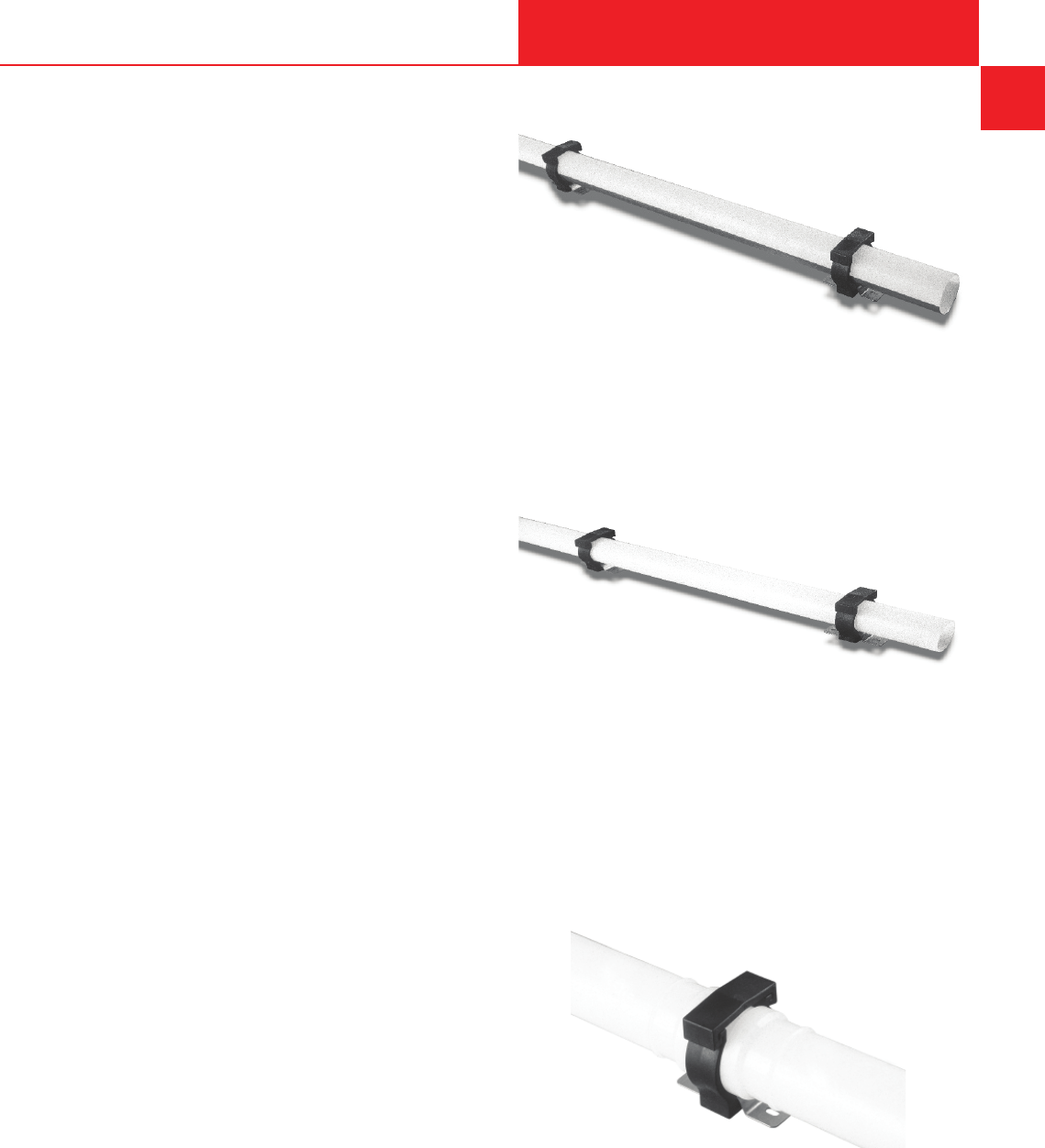
655 Andover Street, Lawrence, MA 02148 • Tel: 800-343-3618, 781-321-5409
Fax: 800-787-6861 • https://www.asahi-america.com • Email: [email protected]
INSTALLATION
General Installation Guidelines
'XHWRWKHORZHUVWLႇQHVVDQGULJLGLW\DVZHOODVWKH
SRWHQWLDOOHQJWKH[SDQVLRQVFDXVHGE\FKDQJHVLQ
WHPSHUDWXUHRIWKHUPRSODVWLFVLQFRPSDULVRQZLWK
PHWDOOLFPDWHULDOVWKHUHTXLUHPHQWVIRUWKH¿[LQJRI
piping elements should be met.
2QOD\LQJRISLSHVDERYHJURXQGH[SDQVLRQDQG
FRQWUDFWLRQVRISLSHVLQERWKUDGLDODQGD[LDOGLUHFWLRQV
must not be hindered; this means installation with radial
clearance, position of compensation facilities, and
control of changes in length by reasonable arrangement
RI¿[HGSRLQWV
Attachments have to be calculated to avoid pinpoint
stresses, meaning the bearing areas have to be as
wide as possible and adapted to the outside diameter if
SRVVLEOHWKHHQFORVLQJDQJOHKDVWREHFKRVHQ!
The surface qualities of the attachments should help to
avoid mechanical damage to the pipe surface.
9DOYHVDQGLQFHUWDLQFDVHVWHHVVKRXOGHVVHQWLDOO\
EHLQVWDOOHGRQDSLSLQJV\VWHPDV¿[HGSRLQWV9DOYH
constructions with the attachment devices integrated
within the valve body are most advantageous.
Installation by Means of Pipe Clips
Attachments made of either steel or thermoplastics are
available for plastic pipes. Steel clips have to be lined
ZLWKWDSHVPDGHRI3(RUHODVWRPHUVRWKHUZLVHWKH
surface of the plastics pipe may be damaged. AGRU
plastics pipe clips as well as pipe holders are suitable for
installation. These may be commonly applied and have
HVSHFLDOO\EHHQDGMXVWHGWRWKHWROHUDQFHVRIWKHSODVWLFV
pipes.
Therefore, they serve as sliding bearing at horizontally
installed piping systems in order to take up vertical
stresses. A further application range of the AGRU pipe
clip is the function as guiding bearing which should
hinder a lateral buckling of the piping system as it can
also absorb transversal stresses.
It is recommended, for smaller pipe diameters
2'PPWRXVHVWHHOKDOIURXQGHGSLSHVDVVXSSRUW
of the piping system in order to enlarge the support
distances.
Figure D-23. Pipe support with steel half shell
3LSHVL]HV2'PPVKRXOGEHVXSSRUWHGE\
PHDQVRISLSHFOLSVZKLFKGRQRW¿[WKHSLSHLQDQD[LDO
direction.
Figure D-24. Pipe clip support
)RU¿[HGSRLQWVDQFKRUVLQWKHSLSLQJV\VWHPUHVWUDLQW
¿WWLQJVVKRXOGEHXWLOL]HGWRJHWKHUZLWKVXLWDEOHSLSH
clips.
7KHUHVWUDLQHG¿WWLQJVZLOOSUHYHQWPRYHPHQWLQWKHD[LDO
GLUHFWLRQEXWZLOOSURYLGHWKHUHTXLUHGÀH[LELOLW\LQWKH
radial direction and provide a stress-free application.
)LJXUH'$QFKRUDQGUHVWUDLQW¿WWLQJVXSSRUW
Hanger Types
When selecting hangers for a system, it is important to
avoid using a hanger that will place a pinpoint load on
D-27
ASAHI/AMERICA
Rev. 2013-A
D
SYSTEM CHARTS
INSTALLATION

655 Andover Street, Lawrence, MA 02148 • Tel: 800-343-3618, 781-321-5409
Fax: 800-787-6861 • https://www.asahi-america.com • Email: [email protected]
WKHSLSHZKHQWLJKWHQHG)RUH[DPSOHD8EROWKDQJHU
is not recommended for thermoplastic piping.
)LJXUH'(ႇHFWVRI8EROWRQSLSH
+DQJHUVWKDWVHFXUHWKHSLSHDURXQGWKHSLSHDUH
preferred. Thermoplastic clamps are also recommended
over metal clamps, as they are less likely to scratch
the pipe in the event of movement. If metal clamps
DUHVSHFL¿HGIRUWKHSURMHFWWKH\VKRXOGEHLQVSHFWHG
for rough edges that could damage the pipe. Ideally, if
a metal clamp is being used, an elastomeric material
should be used in between the pipe and the clamp. This
LVDPXVWIRU39')DQG(&7)(V\VWHPVZKLFKDUH
OHVVWROHUDQWWRVFUDWFKLQJ7KH¿JXUHEHORZLOOXVWUDWHVD
recommended hanger type.
Figure D-27. Recommended clamp
D-28
ASAHI/AMERICA
Rev. 2013-A
D
SYSTEM CHARTS
PRODUCTION AND PACKAGING

655 Andover Street, Lawrence, MA 02148 • Tel: 800-343-3618, 781-321-5409
Fax: 800-787-6861 • https://www.asahi-america.com • Email: [email protected]
Section E
GENERAL INSTALLATION
PRACTICES
Contents
Bending .......................E-2
Socket ........................E-2
Butt/IR ......................... E-5
Electrofusion .................E-14
Hot Air .......................E-15
Extrusion .....................E-18
Mechanical Connections ........E-20
ASAHI/AMERICA
Rev. 2013-A
E-1

655 Andover Street, Lawrence, MA 02148 • Tel: 800-343-3618, 781-321-5409
Fax: 800-787-6861 • https://www.asahi-america.com • Email: [email protected]
BENDING
Pipe Bending
Many thermoplastic piping systems can be bent to
UHGXFHWKHXVDJHRI¿WWLQJV3LSHEHQGLQJSURFHGXUHV
are dependent on the intended radius, material, and
size and wall thickness of the pipe. Consult with
Asahi/America for procedural recommendations.
3RO\SURS\OHQHDQG+'3(FDQEHEHQWLQWKH¿HOGEXW
EHQGLQJ39')LVQRWUHFRPPHQGHG
Figure E-1. Asahi/America pipe allowable bend
SOCKET
Socket Fusion
,QVRFNHWZHOGLQJWKHSLSHHQGDQGVRFNHW¿WWLQJVDUH
heated to welding temperature by means of a socket
and spigot heater inserts. Socket welding may be
manually performed on pipe diameters up to 2” (63 mm).
Sizes above that require a bench socket tool due to the
required joining forces. In sizes greater than 1”, a bench
style machine may be preferred for ease of operation.
E
BENDING
ASAHI/AMERICA
Rev. 2013-A
E-2
Welding Temperature
7KHUHFRPPHQGHGZHOGLQJWHPSHUDWXUHIRU33+335
3(+'DQG39')LVEHWZHHQ)DQG)&
DQG&
Welding Parameters
7DEOH(EHORZFDQEHXVHGDVDUHIHUHQFHZKHQ
VRFNHWZHOGLQJ33DQG3(+'SLSHVDQG¿WWLQJVDW
DQRXWVLGHWHPSHUDWXUHRIDERXW)&ZLWKORZ
air-speed rates.
Table E-1. Welding Parameters
3LSH6L]H
(inches)
A
+HDW6RDN7LPH
(sec)
B
Adjusting Time
(sec)
C
Cooling Time
(min)
1/2 2
7 2
1 6
12 6
1-1/2 6
2 6
2-1/2 30 6
3 6
10
GENERAL INSTALLATION

655 Andover Street, Lawrence, MA 02148 • Tel: 800-343-3618, 781-321-5409
Fax: 800-787-6861 • https://www.asahi-america.com • Email: [email protected]
Welding Process
Hand-Held Socket Fusion
Once the heating element is warmed to the proper
temperature, welding proceeds as follows:
1. )ROORZWKHZHOGLQJSDUDPHWHUVSURYLGHGZLWK
Asahi/America’s socket welding equipment.
2. )ROORZWKHVHVWHSV
a. Cut the pipe faces at right angles, and remove
burrs using a deburring tool.
b. 3(33SLSHUHTXLUHVFUDSLQJDFFRUGLQJWR'86
JXLGHOLQHVXVLQJ$VDKL35(3WRROVWRUHPRYH
oxidation
c. &OHDQWKHSLSHDQG¿WWLQJVZLWKOLQWIUHHSDSHU
and cleansing agents (isopropyl alcohol or
similar).
d. Mark the socket depth with a scraper knife or
marker on the pipe to ensure proper insertion
depth of the pipe during welding.
e. Thoroughly clean heater inserts before each
weld.
3. 4XLFNO\SXVKSLSHDQG¿WWLQJVLQDQD[LDOGLUHFWLRQ
into heater inserts until the pipe bottoms (or meets
WKHPDUNLQJ$YRLGWZLVWLQJZKLOHKHDWLQJ+ROGLQ
place for the heat soak time (column A).
$IWHUWKHKHDWVRDNWLPHUHPRYHWKH¿WWLQJDQGSLSH
from the heating element and immediately push
them together within the changeover time (column
B), without twisting them, until both welding beads
meet. The changeover time is the maximum period
of time between the removal from the heating
HOHPHQWDQGWKH¿QDOVHWWLQJVRIWKHFRPSRQHQWV
Components should be held together and allowed
WRFRROSHUWKHVSHFL¿HGFRROGRZQWLPHSULRUWR
stressing the joint.
Visual Inspection
'XULQJWKH¿QDOMRLQLQJVWHSLWLVLPSRUWDQWWKDWWKHEHDG
IRUPHGRQWKHSLSHPHHWVWKHEHDGRQWKH¿WWLQJ,IWKH
beads do not meet, a small gap will be present. Welds
that have a gap between the fusion beads should be
FXWDQGUHZHOGHGVHH)LJXUH(7KHEHDGRQWKH
SLSHVKRXOGEHXQLIRUPDURXQGRIWKHSLSH%HDGV
that vary in size or disappear altogether are a sign of
improper heating and/or joining.
E
GENERAL INSTALLATION
SOCKET
ASAHI/AMERICA
Rev. 2013-A
E-3
Figure E-2. Socket Fusion Welding Process
Figure E-3. Socket fusion welding samples
Table E-2. Sample Welding Data (time-sec)

655 Andover Street, Lawrence, MA 02148 • Tel: 800-343-3618, 781-321-5409
Fax: 800-787-6861 • https://www.asahi-america.com • Email: [email protected]
Performing of Pressure Test
Before pressure testing, all welding joints have to be
completely cooled down (as a rule, one hour after
the last welding process). The pressure test has to
be performed according to the relevant standard
regulations. The piping system has to be protected
DJDLQVWFKDQJHVRIWKHDPELHQWWHPSHUDWXUH89
radiation).
'HYLFHVIRUKHDWLQJHOHPHQWVRFNHWZHOGLQJDUHXVHG
in workshops as well as at building sites. As single-
purpose machines, they should allow for a maximum
degree of mechanization of the welding process.
Clamping Devices
Marks on work piece surfaces that are caused by special
FODPSLQJGHYLFHVIRUSLSHFRPSRQHQWVPXVWQRWDႇHFW
WKHPHFKDQLFDOSURSHUWLHVRIWKH¿QLVKHGFRQQHFWLRQ
Guide Elements
Together with clamping devices and a heating element,
the guide elements have to ensure that the joining parts
are guided centrically to the heating element and to
each other. If necessary, an adjusting mechanism can
be provided.
E
GENERAL INSTALLATION
SOCKET
ASAHI/AMERICA
Rev. 2013-A
E-4
Machine Design and Safety in Use
In addition to meeting the above requirements for
construction and design, the following points should be
considered for the machine design:
• Stable construction
• 8QLYHUVDOEDVLFFRQVWUXFWLRQVZLYHOOLQJRUUHWUDFWDEOH
auxiliary tools and clamps)
• Quick clamping device
• Maximum degree of mechanization (reproducible
welding process)

655 Andover Street, Lawrence, MA 02148 • Tel: 800-343-3618, 781-321-5409
Fax: 800-787-6861 • https://www.asahi-america.com • Email: [email protected]
BUTT/IR
Butt Fusion (for single wall piping systems)
7KHEXWWIXVLRQRI33+'3(39')DQG(&7)(LV
accomplished with Asahi/America’s recommended butt
fusion welding equipment. Asahi/America provides
ZHOGLQJHTXLSPHQWWRKDQGOHDOOGLDPHWHUVL]HVRႇHUHG
and has an extensive line of equipment available to buy
or rent for every application.
The principle of butt fusion is to heat two surfaces
at the melt temperature, make contact between the
two surfaces, and then allow the two surfaces to fuse
together by application of force. The force causes the
ÀRZRIWKHPHOWHGPDWHULDOVWRMRLQ8SRQFRROLQJWKH
two parts are united. Nothing is added or changed
chemically between the two components being joined.
Butt fusion does not require solvents or glue to join
material.
Butt fusion is recognized as the industry standard,
providing high integrity and reliability. It does not
require couplings or added material. The procedure,
recommended by Asahi/America, conforms to ASTM
'IRU-RLQLQJ3UDFWLFHVRI3RO\ROH¿Q0DWHULDOVDQG
WKHUHFRPPHQGHGSUDFWLFHVRIWKH$60(%&RGH
Welding Process
2QFHWKHSLSHVRU¿WWLQJVKDYHEHHQVHFXUHGLQWKH
proper welding equipment, as well as aligned and
planed with the facing tool (planer), and the heating
element is warmed to the proper temperature, welding
proceeds as follows:
1. )ROORZWKHZHOGLQJSDUDPHWHUVWHPSHUDWXUHWLPH
and force) provided with Asahi/America’s butt fusion
HTXLSPHQWVHHVDPSOHZHOGLQJGDWDLQ7DEOH(
2. Insert the heating element between secured pipes
RU¿WWLQJVPDNLQJVXUHIXOOFRQWDFWLVPDGHDURXQG
surfaces.
3. Apply full welding pressure, as shown in (Column
$XQWLODPD[LPXP´ULGJHRIPHOWHGPDWHULDO
is present around the outside circumference of both
SLSHVRU¿WWLQJV7KLVLQGLFDWHVWKDWSURSHUPHOWÀRZ
has been accomplished and further guarantees two
parallel surfaces.
Reduce the pressure to the recommended
melt pressure (Column B), and begin timing for
recommended heat soak time (Column C).
E
GENERAL INSTALLATION
BUTT/IR
ASAHI/AMERICA
Rev. 2013-A
E-5
At the end of the heat soak time, in a quick and
VPRRWKPRWLRQVHSDUDWHWKHSLSH¿WWLQJIURPWKH
heating element, and then apply weld pressure
&ROXPQ(,WLVLPSRUWDQWWRJUDGXDOO\LQFUHDVH
pressure to achieve welding pressure. The weld
must be performed within the allowable changeover
WLPH&ROXPQ'&KDQJHRYHUWLPHLVWKHPD[LPXP
SHULRGRIWLPHZKHQHLWKHUWKHSLSHVRU¿WWLQJVFDQ
be separated from the heating element, yet still retain
VXႈFLHQWKHDWIRUIXVLRQ%ULQJWKHPHOWHGHQG
together to its welding pressure.
6. The heat soak time may need to be increased
in cold or windy environments. Several practice
welds should be conducted at the installation site
to ensure that welding can be performed, as a
test of conditions. Consult Asahi/America for any
PRGL¿FDWLRQRIZHOGSDUDPHWHUV
7. A visual inspection must be performed as well. After
joining, a bead surrounding the whole circumference
will have been created. A good weld will have two
V\PPHWULFDOEHDGVRQERWKWKHSLSHDQG¿WWLQJVWKDW
are almost equally sized and have a smooth surface.
Allow components to cool to the touch or until a
¿QJHUQDLOFDQQRWSHQHWUDWHWKHEHDG7KLVLV
UHFRPPHQGHGLQ$670'6HFWLRQ7KH
SLSHVRU¿WWLQJVPD\EHUHPRYHGIURPWKHZHOGLQJ
HTXLSPHQWDWWKHFRPSOHWLRQRIWKHVSHFL¿HGFRROLQJ
time.
'RQRWSXWFRPSRQHQWVXQGHUVWUHVVRUFRQGXFWD
SUHVVXUHWHVWXQWLOFRPSOHWHFRROLQJWLPH&ROXPQ)
has been achieved.
Table E-4. Sample Welding Data
(time-sec, pressure-psi)

655 Andover Street, Lawrence, MA 02148 • Tel: 800-343-3618, 781-321-5409
Fax: 800-787-6861 • https://www.asahi-america.com • Email: [email protected]
Figure E-4. Butt fusion welding process
Figure E-5. Butt fusion welding example
Butt Fusion (for double wall piping
systems)
,QVWDOODWLRQRI'XR3UR
®
&KHP3URORN)OXLG/RN
®
, and
3RO\)OR
®
piping systems involves the use of thermal
butt fusion for both the carrier and containment piping.
'HSHQGLQJRQWKHV\VWHPGHVLJQWKHVL]HPDWHULDO
and layout will determine the required equipment.
$VDKL$PHULFDRႇHUVDOORIWKHQHFHVVDU\VL]HVDQG
styles of equipment for any installation type.
Systems that are fully restrained and consist of the same
carrier and containment materials can take advantage
of the simultaneous butt fusion method. Simultaneous
fusion allows for the quickest and easiest installation
E\FRQGXFWLQJWKHLQQHUDQGRXWHUZHOGDWRQFH)RU
'XR3UR
®
designs that consist of dissimilar materials or
require the inner (carrier) piping to be loose for thermal
expansion, use the staggered welding procedure.
E
GENERAL INSTALLATION
BUTT/IR
ASAHI/AMERICA
Rev. 2013-A
E-6
Staggered welding consists of welding the inner carrier
SLSH¿UVWDQGWKHFRQWDLQPHQWSLSLQJVHFRQG)LQDOO\LID
leak detection cable system is required, special heating
elements or procedures are provided to accommodate
for pull ropes.
The basic installation techniques for double containment
piping systems follow the principles that apply to
ordinary plastic piping applications.
Simultaneous Butt Fusion Method
The object of simultaneous fusion is to prepare both
the carrier and containment pipe so that both pipes are
¿[HGWRHDFKRWKHUDQGWKHUHIRUHFDQEHZHOGHGDWWKH
same time. In some systems, such as Asahi/America’s
)OXLG/RN
®
DQG3RO\)OR
®
, only simultaneous fusion can
be performed due to their design. The net result of the
simultaneous method is a substantial reduction of labor
and equipment requirements.
As previously discussed, simultaneous fusion is only
applicable for welding installations that have the
same carrier and containment material. In addition,
simultaneous fusion is used for systems that are
FRPSOHWHO\UHVWUDLQHG3ULRUWRXVLQJWKHVLPXOWDQHRXV
method, an analysis based on operating conditions
is required in order to determine the suitability
of a restrained design. Contact Asahi/America’s
(QJLQHHULQJ'HSDUWPHQWIRUDVVLVWDQFH
Equipment
)RUVLPXOWDQHRXVZHOGLQJVWDQGDUGEXWWIXVLRQ
equipment used for single wall systems is used. No
VSHFLDOKHDWLQJHOHPHQWVDUHUHTXLUHG)RU'XR3UR
®
DQG)OXLG/RN
®
systems, hot air or extrusion welding
equipment is necessary to weld the support discs and
VSLGHUFOLSVWRWKHSLSHV+RWDLUZHOGLQJLVQRWXVHGIRU
any pressure rated components.
Fittings
)LWWLQJVXVHGIRUVLPXOWDQHRXVIXVLRQDUHHLWKHUPROGHG
or prefabricated at the factory with the necessary
VXSSRUWGLVFV3UHIDEULFDWHG¿WWLQJVJUHDWO\UHGXFHWKH
DPRXQWRIKRWDLUZHOGLQJUHTXLUHGLQWKH¿HOGDQG
in turn, reduce labor time. If an installation is pipe-
intensive, labor costs may be reduced by ordering
prefabricated pipe spools in longer dimensions.

655 Andover Street, Lawrence, MA 02148 • Tel: 800-343-3618, 781-321-5409
Fax: 800-787-6861 • https://www.asahi-america.com • Email: [email protected]
Welding Procedure
The welding theory for double containment is the same
as for single wall pipe. Asahi/America has developed
welding tables for the appropriate heating times and
forces for simultaneous fusion. The following procedure
outlines the necessary steps for simultaneous fusion.
Double Wall Pipe Assembly
3LSHVDQG¿WWLQJVLQDVLPXOWDQHRXVGRXEOHZDOOV\VWHP
from Asahi/America are always prefabricated at the
factory and supplied to a job-site ready for butt fusion.
+RZHYHUZKHQYDU\LQJOHQJWKVDUHUHTXLUHGLQWKH
¿HOGDVVHPEO\LVQHFHVVDU\,QVWDJJHUHGZHOGLQJ
V\VWHPVSLSHDQG¿WWLQJDVVHPEO\LVFRPPRQ7KH
EDVLFSURFHGXUHIRUSURSHUO\DVVHPEOLQJ'XR3UR
®
and
)OXLG/RN
®
components is outlined below.
,QGRXEOHFRQWDLQPHQWSLSLQJDVVHPEO\SUR¿FLHQF\LQ
hand and extrusion welding procedures is necessary.
1. A good weld requires proper preparation of
the material. The pipe should be free of any
impurities, such as dirt, oil, etc. Additionally, some
thermoplastics develop a thin layer of oxidized
molecules on the surface that require scraping or
JURXQGLQJRIWKHPDWHULDO$QRWKHUHႇHFWHVSHFLDOO\
ZLWK+'3(LVWKHPLJUDWLRQRIXQFKDLQHGORZHU
density molecules to the surface caused by internal
pressure of the material. This gives the usually
³ZD[\´VXUIDFHDSSHDUDQFHRI+'3(*ULQGLQJRU
VFUDSLQJLVUHTXLUHG:LSHRႇDQ\GXVWZLWKDFOHDQ
FORWK'RQRWXVHVROYHQWVRUFOHDQHUVWKH\LQWURGXFH
FKHPLFDOVZLWKXQNQRZQDQGOLNHO\QHJDWLYHHႇHFWV
E
GENERAL INSTALLATION
BUTT/IR
ASAHI/AMERICA
Rev. 2013-A
E-7
2. 8VLQJ7DEOH(SODFHWKHPROGHGRUIDEULFDWHG
support spider clips, with tops aligned, on the carrier
SLSHDQGWKHQKRWJDV33RUH[WUXVLRQZHOG
+'3(WKHFOLSVLQWRSODFHDVVKRZQLQ)LJXUH)
8VHWKHUHTXLUHGDPRXQWRIFOLSVRQWKHIXOOOHQJWKV
of the carrier pipe.
Figure E-6. Spider clip attached to carrier pipe
3. Insert carrier pipe into containment pipe. Be sure the
two pipes have been stored in the same environment
for equal expansion or contraction to occur before
welding end centralizers into place.
Figure E-7. Carrier pipe and spider clips inserted
into containment pipe
)RUVLPXOWDQHRXVZHOGLQJHQGFHQWUDOL]HUVNQRZQ
as support discs, are hot air or extrusion welded to
the carrier and containment pipes. This prevents any
movement of the carrier pipe during the butt fusion
process. The alignment must match that of the spider
supports for the installation of leak detection cables,
DVZHOODVIRUOHDNÀRZ,Q¿WWLQJDVVHPEOLHVLQVWDOO
end centralizers only. All centralizers are installed
DSSUR[LPDWHO\´IURPWKHHQGVXVLQJDPPZHOGLQJ
rod.
Table E-5. Double Containment Internal Support
Spacing (inches)

655 Andover Street, Lawrence, MA 02148 • Tel: 800-343-3618, 781-321-5409
Fax: 800-787-6861 • https://www.asahi-america.com • Email: [email protected]
Figure E-8. Support disc attached to carrier and
containment pipes
7KHSLSHDQG¿WWLQJZLWKVXSSRUWGLVFVDUHQRZUHDG\
for simultaneous butt fusion using the recommended
$670'MRLQLQJSUDFWLFHV
Butt Fusion Procedure for Double Wall Pipe
Without Leak Detection Cable Systems
Simultaneous fusion as outlined below is ideal for:
• 'XR3UR
®
systems made of similar carrier and
containment material
• )OXLG/RN
®
+'3(V\VWHPV
• Restrained double wall systems only
• $OO3RO\)OR
®
systems
)XVLQJ'XR3UR
®
DQG)OXLG/RN
®
is accomplished with
Asahi/America’s recommended butt fusion welding
equipment. Asahi/America provides welding equipment
WRKDQGOHDOOGLDPHWHUVDQGV\VWHPFRQ¿JXUDWLRQV
(TXLSPHQWLVDYDLODEOHIRUUHQWDORUSXUFKDVH
The principle of butt fusion is to heat two surfaces
at a fusion temperature, make contact between the
two surfaces, and then allow the two surfaces to fuse
together by application of force. After cooling, the
original interfaces are gone and the two parts are united.
Nothing is added or changed chemically between the
two pieces being joined.
Butt fusion is recognized in the industry as a cost-
HႇHFWLYHMRLQLQJPHWKRGRIYHU\KLJKLQWHJULW\DQG
reliability. The procedure, recommended by Asahi/
$PHULFDFRQIRUPVWR$670'IRU-RLQLQJ
3UDFWLFHVRI3RO\ROH¿Q0DWHULDOVDQGWKHUHFRPPHQGHG
SUDFWLFHVRIWKH$60(%&RGH&KHPLFDO3ODQWDQG
3HWUROHXP5H¿QHU\3LSLQJ
E
GENERAL INSTALLATION
BUTT/IR
ASAHI/AMERICA
Rev. 2013-A
E-8
The procedure is outlined as follows: Once the pipes
RU¿WWLQJVKDYHEHHQVHFXUHGLQWKHSURSHUZHOGLQJ
equipment with the tops and annular space aligned,
and the heating element is warmed to the proper
temperature, welding should proceed as follows:
1. )ROORZWKHZHOGLQJSDUDPHWHUVSURYLGHGZLWK
Asahi/America butt fusion equipment (see sample
ZHOGLQJGDWDLQ7DEOH(
Table E-6. Sample Welding Data
(time-sec, pressure-psi)
2. 7RHQVXUHWKDWWKHFDUULHUSLSHLVSODQHGDQGÀXVK
with the containment pipe, put four marks on the
end of the carrier pipe at three, six, nine, and twelve
o’clock prior to planing. If the outer pipe is completely
planed and the marks on the carrier have been
removed, planing is complete. With experience,
visual inspection can determine that the planing
process is complete. Remove all shavings, and
UHFKHFNDOLJQPHQW)RU3RO\)OR
®
, the pipes should
be installed in the machines so that the ribs do not
DOLJQWKHUHE\DOORZLQJDQ\ÀXLGWRÀRZWRWKHORZ
point of the annular space in the event of a leak.
)LJXUH(3ODQHFDUULHUSLSHÀXVKZLWKFRQWDLQPHQW
pipe
3. Insert a heating element between secured pipes
RU¿WWLQJVPDNLQJVXUHIXOOFRQWDFWLVPDGHDURXQG
surfaces.

655 Andover Street, Lawrence, MA 02148 • Tel: 800-343-3618, 781-321-5409
Fax: 800-787-6861 • https://www.asahi-america.com • Email: [email protected]
Figure E-10. Insert heating element between pipe
ends
$SSO\IXOOZHOGLQJSUHVVXUHDVVKRZQLQ7DEOH(
&ROXPQ(XQWLODPD[LPXP´ULGJHRIPHOWHG
material is noticed around the outside circumference
of the components. This indicates that proper melt
ÀRZKDVEHHQDFFRPSOLVKHGDQGIXUWKHUJXDUDQWHHV
two parallel surfaces.
Figure E-11. Apply welding pressure to the heating
element
Reduce the pressure to the recommended melt
pressure (Column B), and begin timing for the
recommended heat soak time (Column C).
6. At the end of the heat soak time, in a quick and
VPRRWKPRWLRQVHSDUDWHHLWKHUWKHSLSHVRU¿WWLQJV
remove the heating element, and then apply weld
SUHVVXUH&ROXPQ(,WLVLPSRUWDQWWRJUDGXDOO\
increase pressure to achieve welding pressure in
&ROXPQ(7KHZHOGPXVWEHSHUIRUPHGZLWKLQWKH
DOORZDEOHFKDQJHRYHUWLPH&ROXPQ'&KDQJHRYHU
time is the maximum period of time when either
WKHSLSHVRU¿WWLQJVFDQEHVHSDUDWHGIURPWKH
KHDWLQJHOHPHQW\HWVWLOOUHWDLQVXႈFLHQWKHDWIRU
fusion. Bring the melted ends together to its welding
pressure.
E
GENERAL INSTALLATION
BUTT/IR
ASAHI/AMERICA
Rev. 2013-A
E-9
Figure E-12. Bring pipe ends together, and apply
welding pressure
7. The heat soak time should be increased if the
environment is cold or windy or if either the pipes
RU¿WWLQJVDUHFROG$VDWHVWRIHQYLURQPHQWDO
conditions, several practice welds should be done
at the installation site to ensure that welding can
be performed. Consult with Asahi/America for
recommendations on cold weather welding.
A visual inspection must be performed as well. After
joining, a bead surrounding the whole circumference
will have been created. A good weld will have a
V\PPHWULFDOEHDGRQERWKSLSHVRU¿WWLQJVDQGD
smooth surface.
Figure E-13. Visual inspection of welds
Allow components to cool to the touch or until
D¿QJHUQDLOFDQQRWSHQHWUDWHWKHEHDG7KLVLV
UHFRPPHQGHGLQ$670'6HFWLRQ7KH
SLSHVRU¿WWLQJVPD\EHUHPRYHGIURPWKHZHOGLQJ
equipment at this time.
10. 'RQRWSXWSLSHRU¿WWLQJVXQGHUDQ\W\SHRIVWUHVV
or conduct a pressure test until the complete cooling
WLPH&ROXPQ)KDVEHHQDFKLHYHG

655 Andover Street, Lawrence, MA 02148 • Tel: 800-343-3618, 781-321-5409
Fax: 800-787-6861 • https://www.asahi-america.com • Email: [email protected]
Butt Fusion Procedure for Double Wall Pipe
With Leak Detection Cable Systems
This method is available for the following systems:
• 'XR3UR
®
made of similar material on the carrier and
containment
• )OXLG/RN
®
+'3(V\VWHP
• Restrained systems only
Asahi/America split-leak detection heating elements
allow both the carrier and containment pipes to be
welded simultaneously, with a pull cable in place. The
PLUURUGHVLJQDVVKRZQLQ)LJXUH(LVFDSDEOHRI
splitting apart and wrapping around a wire. The small
hole centered at the bottom of the heater allows a pull
wire to be in place during the fusion process. Once the
pipe is heated, the heating element is split apart and
UHPRYHGOHDYLQJWKHZLUHLQSODFHIRUWKH¿QDOSLSH
joining.
Figure E-14. Split heating elements for leak
detection systems
A short piece of wire is attached to the pull rope on both
ends after planing. The wire runs through the heater
during welding in order to prevent the damaging or
PHOWLQJRIWKHSXOOURSHVHH)LJXUHV(WR($IWHU
each section is complete, the wire is pulled down to the
next joint to be welded. The installation of the pull rope
is at the six o’clock position. A continuous pull rope, free
from knots and splices, should be pulled through as the
system is assembled.
E
GENERAL INSTALLATION
BUTT/IR
ASAHI/AMERICA
Rev. 2013-A
E-10
Figure E-16. Pull rope connected by wire through
heating element
Figure E-17. Pipe ends heated with pull rope
installed
Figure E-18. Welding complete with pull rope
installed
)ROORZWKHVWDQGDUGEXWWIXVLRQSURFHGXUHIRUZHOGLQJ
Other methods for welding with a solid heating element
are available that will accommodate a leak detection
cable system.
Figure E-15. Planing ends with pull rope installed

655 Andover Street, Lawrence, MA 02148 • Tel: 800-343-3618, 781-321-5409
Fax: 800-787-6861 • https://www.asahi-america.com • Email: [email protected]
Staggered Butt Fusion Method
8VLQJWKHVWDJJHUHGIXVLRQSURFHGXUHWRDVVHPEOH
D'XR3UR
®
system is more complicated and labor-
LQWHQVLYHWKDQVLPXOWDQHRXVIXVLRQ+RZHYHULWRႇHUV
the ability to install a double containment system
ZLWKDÀH[LEOHLQQHUSLSHRUZLWKGLႇHUHQWFDUULHUDQG
containment materials. Asahi/America provides all of the
necessary equipment for this welding method.
,QVWDJJHUHGZHOGLQJWKHFDUULHUSLSHLVZHOGHG¿UVW
followed by the containment pipe. In a staggered
system, there are no end support discs. This allows for
the movement of the carrier components. It is important
to plan which welds will be made and in what order.
(QRXJKÀH[LELOLW\LVUHTXLUHGWRPRYHWKHLQQHUSLSHRXW
from the outer pipe to perform a carrier weld.
In long, straight runs, the procedure is simple, due to
VLJQL¿FDQWFDUULHUSLSHPRYHPHQW,QV\VWHPVWKDWDUH
¿WWLQJLQWHQVLYHWKHSURFHGXUHEHFRPHVPRUHGLႈFXOW
because the pipe movement is limited to the amount
of annular space between the carrier and containment
¿WWLQJVVHH)LJXUH(
Welding Procedure
1. Begin by attaching spider clips to the carrier pipe
(follow steps in double wall pipe assemblies).
2. ,QVHUWFDUULHUSLSHRU¿WWLQJVLQWRWKHDSSURSULDWH
containment line. At the start of a system, it may
EHHDVLHUWRZHOGWKHFDUULHU¿UVWDQGWKHQVOLGHWKH
FRQWDLQPHQWSLSHRYHUWKHFDUULHUSLSH+RZHYHUDV
the installation moves along, this will not be possible.
Note: If containment piping has been roughly cut,
make sure to plane it prior to welding the carrier
pipe. Once the carrier is welded, the containment
pipe cannot be planed.
3. In the machine, use the two innermost clamps to
KROGWKHFDUULHUSLSHIRUZHOGLQJ8VHWKHRXWHU
clamps to hold the containment pipe in place. In
FDVHVZKHUHPRYHPHQWLVOLPLWHG¿WWLQJFODPSVZLOO
be necessary to hold the carrier pipe.
Once all of the pieces are locked in place, weld the
carrier pipe using standard butt fusion techniques
VHH)LJXUHV($DQG(%
Once the carrier weld is complete, remove the inner
clamps and pull the containment pipe together for
ZHOGLQJVHH)LJXUHV(&DQG('$WWKLV
point, switch all clamps to containment sizing. It may
E
GENERAL INSTALLATION
BUTT/IR
ASAHI/AMERICA
Rev. 2013-A
E-11
be preferable to use two machines to eliminate the
constant changing of clamps. Also, in some designs,
two machines may be required to weld the two
GLႇHUHQWGLDPHWHUSLSHV
6. To weld the containment pipe, a split annular mirror
LVUHTXLUHGVHH)LJXUH()7KHPLUURULVKLQJHG
to let it wrap around the carrier pipe while welding
the containment pipe.
7. It is important to ensure that the mirror is properly
centered so it does not rest on and melt the carrier
pipe.
Once the mirror is in place, the welding procedure is
the same as standard single wall butt fusion.

655 Andover Street, Lawrence, MA 02148 • Tel: 800-343-3618, 781-321-5409
Fax: 800-787-6861 • https://www.asahi-america.com • Email: [email protected]
A. Cut carrier and containment pipes to length L
B. Pull carrier elbow out of containment elbow and
weld to carrier pipe
C. Weld containment elbow to containment pipe
D. Flex carrier elbow and pipe toward tee and weld
to carrier tee pipe
E. Weld containment pipe to containment tee
F. Annular heating element
Figure E-19. Staggered butt fusion
E
GENERAL INSTALLATION
BUTT/IR
ASAHI/AMERICA
Rev. 2013-A
E-12
Helpful Hints
• :KHQZHOGLQJ39')DQG+DODU
®
, move swiftly while
UHPRYLQJWKHPLUURUDQGMRLQLQJWKHSLSHV'HOD\HG
reaction will cause the material to cool and a “cold
ZHOG´WRIRUP39')DQG+DODU
®
FRRORႇPRUHTXLFNO\
than polypropylene.
• Always plan welding so the longest and heaviest
section of pipe is positioned on the stationary side of
the welding machine.
• Start at one end, and work to the other end of the
SLSHV\VWHP'RQRWVWDUWRQWZRGLႇHUHQWHQGVDQG
meet in the middle. Moving the pipe for welding will
EHH[WUHPHO\GLႈFXOWRULPSRVVLEOH
• :KHQSODQLQJORQJVWULSVLQGLFDWHWKDW\RXDUHÀXVK
all the way around.
• Consult the factory for a proper equipment
recommendation for the system being installed.
• Machines are extremely adaptable and can be
SRVLWLRQHGLQPDQ\ZD\VWRDFFRPPRGDWHGLႈFXOW
welds.

655 Andover Street, Lawrence, MA 02148 • Tel: 800-343-3618, 781-321-5409
Fax: 800-787-6861 • https://www.asahi-america.com • Email: [email protected]
IR Fusion
Improving upon conventional butt fusion, IR welding
uses a non-contact method. IR welding uses the critical
welding parameters of heat soak time, changeover time,
DQGMRLQLQJIRUFHDVIRXQGZLWKEXWWIXVLRQ+RZHYHU
by avoiding direct contact with the heating element, IR
fusion produces a cleaner weld with more repeatable
and smaller bead sizes. The end result is a superior
weld for high purity applications.
7KHJUDSKLQ)LJXUH(RXWOLQHVWKHIRUFHVDSSOLHG
during the non-contact joining process. Notice that the
ramp-up force to full joining pressure is a smooth curve
ZKHUHIRUFHLVJUDGXDOO\DVFHQGLQJRYHUWLPH(YHQ
force build-up is critical to join material without creating a
cold joint.
Welding Process
Material is prepared for IR fusion by creating smooth,
arid, and level surfaces among the ends to be joined.
Butting the material against an internal planer acts as a
centering and leveling device. The planer is then used
to cut a clean and smooth surface. The material should
then be checked for vertical and horizontal alignment.
Welding machines should allow for minor adjustments to
the vertical and horizontal orientation of the material.
2QFHDOLJQPHQWKDVEHHQYHUL¿HGWKHPDWHULDOLVKHDWHG
by close proximity to the heating source. Through
radiant heat and proper heat soak time, the material
becomes molten to allow physical bonding between the
two pieces. After the heating source has been removed,
the material should be joined together in a steady
manner, slowly ramping up the force until the desired
joining force has been achieved.
E
GENERAL INSTALLATION
BUTT/IR
ASAHI/AMERICA
Rev. 2013-A
E-13
Ramping up and monitoring the force is critical for
repeatable and successful IR welding. This ensures
that the molten material has joined at the right force and
prevents against cold welds, which are caused by the
molten material being overly pushed to the inside and
outside of the weld zone.
Figure E-20. IR fusion welding process
Figure E-21. IR fusion timing diagram

655 Andover Street, Lawrence, MA 02148 • Tel: 800-343-3618, 781-321-5409
Fax: 800-787-6861 • https://www.asahi-america.com • Email: [email protected]
ELECTROFUSION
Electrofusion Welding
(OHFWURIXVLRQLVDVLPSOL¿HGDQGVDIHPHWKRGRIMRLQLQJ
SLSHDQGRU¿WWLQJVEDVHGRQPHOWLQJWKHRXWHUVXUIDFH
of the pipe and the inner surface of the electrofusion
FRXSOLQJE\XVLQJDQLQWHJUDOHOHFWULFZLUH(OHFWURIXVLRQ
LVDFRVWHႇHFWLYHPHWKRGIRUMRLQLQJSRO\SURS\OHQHDQG
+'3(SLSH$VDQDOWHUQDWLYHWREXWWIXVLRQHOHFWURIXVLRQ
can be used for repairs, double containment assembly,
DQGGLႈFXOWFRQQHFWLRQVLQWLJKWTXDUWHUV
Welding Equipment
The Asahi electrofusion equipment performs the welding
IRUDOORI$VDKL$PHULFD¶VHOHFWUR¿WWLQJV7KHFRQWUROER[
has a computerized command system for fully automatic
FRQWURODQGHQHUJ\VXSSO\PRQLWRULQJ(DFK¿WWLQJKDVD
bar code label, which contains the information needed
for correct fusion. The welding time is preprogrammed
at the factory and set by the use of the bar code. Simply
scan the bar code to set up the machine for material to
be joined.
Preparation Before Welding
Cut pipe at right angles, and mark the insert length
LQVHUWOHQJWK VRFNHWOHQJWK)RUVXFFHVVIXOZHOGLQJ
it is essential to clean and scrape the surface of the
parts to be joined. In addition, cuts must be straight to
ensure proper insertion into the coupling. Scraping must
be done using a proper hand-operated or mechanical
VFUDSHU'RQRWXVHWRROVVXFKDVUDVSHPHU\SDSHURU
sand paper.
Slide the socket on the prepared end of pipe right to
its center stop until it reaches the marking. Insert the
VHFRQGSLSHHQGRU¿WWLQJLQWRWKHVRFNHWDQGFODPS
both pipes into the holding device. The clamping device
protects the components from being pushed out during
fusion.
Figure E-22. Electrofusion welding setup
E
GENERAL INSTALLATION
ELECTROFUSION
ASAHI/AMERICA
Rev. 2013-A
E-14
Welding Procedure
Observe the operating instructions for the welding
GHYLFHDVLQGLYLGXDOWRROVPD\YDU\3OXJW\SHVRFNHW
connections should be turned upward and then
connected with the cable.
After the welding equipment has been properly
connected, the welding parameters are input by means
of the bar code reader. An audio signal will acknowledge
the data input.
Figure E-23. Initial heating occurs in coupling
3UHVVLQJWKHVWDUWNH\LQLWLDWHVWKHZHOGLQJSURFHVV7KH
time on the display is also programmed into the machine
and allows the correct heating time for various pipe
sizes.
Figure E-24. Molton material from both coupling and
pipes form weld
Figure E-25. Completed electrofusion weld

655 Andover Street, Lawrence, MA 02148 • Tel: 800-343-3618, 781-321-5409
Fax: 800-787-6861 • https://www.asahi-america.com • Email: [email protected]
'XULQJWKHZHOGLQJSURFHVVLQFOXGLQJWKHFRROLQJWLPH
the clamping device should remain in place. The end of
the welding process is indicated by an audio signal.
The welding indicator on the socket performs visual
control.
Before pressure testing, all welded joints must have
completely cooled down based on the welding
parameters provided with the equipment. The pressure
test must be performed according to recommended
procedures.
HOT AIR
Welding Method
+RWDLUJDVZHOGLQJLVWKHSURFHVVRIIXVLQJDEHDGRI
material against a like material. This welding is common
with sheet fabrication and applications not requiring
pressure resistance. Asahi/America uses hot air (gas)
welding to locate support discs for pipe centering in its
'XR3UR
®
system.
In hot air (gas) welding, the heat transfer medium is a
heated gas, either nitrogen or clean air. Originally, the
use of nitrogen proved most successful, preventing
material contamination and oxidation. With today’s
material quality and equipment technology, nitrogen is
becoming less common, except with critical materials.
The combination of clean, oil and moisture-free air with
the controlled temperature proves equally successful,
eliminating the continuous expense of the inert gas.
7KHWHPSHUDWXUHRIWKHKRWDLUUDQJHVEHWZHHQ)
DQG)&DQG&IRU+'3(DQG)WR
)&WR&IRU33ZKHQRXWVLGHZHOGLQJ
FRQGLWLRQVDUHDERXW)&7KHWHPSHUDWXUH
range will vary with changing ambient conditions.
To accomplish high-quality welds, it is important that the
¿OOHUVZHOGLQJURGDUHRIWKHVDPHPDWHULDODQGW\SH
7KHPRVWFRPPRQZHOGLQJ¿OOHUVDUHPPDQGPP
URXQG7KHUHDUHDOVRVSHFLDOSUR¿OHVVXFKDVRYDODQG
triangular rods. The welding tip used must also match
the cross section of the welding rod.
4XDOL¿FDWLRQRI:HOGHUDQG5HTXLUHPHQWV
on Welding Devices
The plastics welder must have obtained the knowledge
and skill required for the performance of welding
processes. As a rule, this would mean that he is a
TXDOL¿HGSODVWLFVZRUNHUDQGZHOGHUZKRFRQWLQXRXVO\
E
GENERAL INSTALLATION
HOT AIR
ASAHI/AMERICA
Rev. 2013-A
E-15
SUDFWLFHVRUGLVSOD\VORQJWLPHH[SHULHQFH+RWJDV
welding machines have to comply with the requirements,
DFFRUGLQJWRJXLGHOLQH'96SDUW
Welding of E-CTFE
7KHFKRLFHRIJDVLVDYHU\LPSRUWDQWIDFWRULQ(&7)(
ZHOGLQJ,WLVQRWQHFHVVDU\WRXVHQLWURJHQLQ(&7)(
ZHOGLQJJRRGTXDOLW\(&7)(ZHOGVFDQEHREWDLQHG
when a clean and dry source of air is used. Welding in
nitrogen is recommended only when the welding facility
lacks a clean and dry source of air.
Safety Precautions for E-CTFE
:KHQZHOGLQJ(&7)(PHOWWHPSHUDWXUHVRI!)
&UHOHDVHK\GURJHQFKORULGHDQGK\GURÀXRULFV
They could be toxic at higher concentrations and
should not be breathed in. The recommended load
OLPLWDFFRUGLQJWR7:$LVSSPIRU+&,DQGSSPIRU
+),I(&7)(YDSRUVDUHLQKDOHGWKHSHUVRQVKRXOG
be brought out into fresh air, and medical aid should
be requested immediately, as there is a danger of
polymer fever. The following safety measures should be
considered:
• +DYHJRRGYHQWLODWLRQLQWKHZRUNSODFHRUXVH
breathing protection)
• 8VHH\HSURWHFWLRQ
• 8VHKDQGSURWHFWLRQ
Air Supply
)RUKRWJDVZHOGLQJDLULVQRUPDOO\VXSSOLHGE\D
compressed air network, compressor, pressure gas
bottle, or ventilator. The air supplied has to be clean and
free of water and oil to avoid decreases in the quality
of the welding seam and the lifetime of the welding
devices. Therefore, adequate oil and water separators
have to be used. The air volume supplied to the device
has to be adjustable and maintained constantly, as it is
DPDLQIDFWRULQÀXHQFLQJWKHWHPSHUDWXUHFRQWURORIWKH
device.
Welding Devices (with built-in ventilator)
The devices are comprised of a handle, a built-
in ventilator, heating, a nozzle, and an electrical
FRQQHFWLQJFDEOH'XHWRWKHLUFRQVWUXFWLRQIHDWXUHV
they can be used at sites where an external air supply
is not available. On account of their dimensions and
weight, they are less suitable for longer lasting welding
processes.

655 Andover Street, Lawrence, MA 02148 • Tel: 800-343-3618, 781-321-5409
Fax: 800-787-6861 • https://www.asahi-america.com • Email: [email protected]
Requirements for Design
The ventilator has to supply the quantity of air required
for welding various types of plastics to all nozzles (see
',1SDUW7KHHOHFWULFDOFLUFXLWKDVWRHQVXUH
that the heating is only turned on when the ventilator is
operating. The noise level of the ventilator has to comply
with the relevant stipulations.
Safety Requirements
The nozzles used for the particular devices have to be
securely fastened and easily exchangeable, even when
heated. The material must be corrosion-proof and of low
scaling. In order to prevent heat from dissipating, the
surface of the nozzle has to be as smooth as possible,
HJSROLVKHG)RUUHGXFLQJIULFWLRQWKHLQQHUVXUIDFHRI
the slide rail of the drawing nozzle has to be polished.
The same applies to the sliding surfaces of tacking
nozzles. In order to avoid strong air vortex at the outlet
of the nozzle, the round nozzles have to be straight for
DWOHDVW[GG RXWOHWGLDPHWHURIWKHQR]]OHLQIURQW
of the outlet.
Preparations for Welding
Before starting the welding process, check the heated
air temperature adjusted on the welding machine.
Measurement is performed by means of a control
WKHUPRFRXSOHLQVHUWHGDSSUR[LPDWHO\PPLQWRWKH
nozzle, and with rod-drawing nozzles in the opening of
the main nozzle. The diameter of the thermocouple must
not exceed 1 mm. Air quantity is measured by means
RIDÀRZFRQWUROLQVWUXPHQWEHIRUHWKHDLUVWUHDPHQWHUV
into the welding machine.
Processing Guidelines
Install welding tent or equivalent if weather conditions
suggest. A good weld requires proper preparation of
the material. The part should be free of any impurities
such as dirt, oil, etc. Additionally, some thermoplastics
develop a thin layer of oxidized molecules on the
surface that require scraping or grounding of the
PDWHULDO$QRWKHUHႇHFWHVSHFLDOO\ZLWK+'3(LVWKH
migration of unchained lower density molecules to the
surface caused by internal pressure of the material. This
JLYHVWKHXVXDOO\³ZD[\´VXUIDFHDSSHDUDQFHRI+'3(
*ULQGLQJRUVFUDSLQJRIWKHVXUIDFHLVUHTXLUHG:LSH
RႇDQ\GXVWZLWKDFOHDQFORWK'RQRWXVHVROYHQWVRU
FOHDQHUVWKH\LQWURGXFHFKHPLFDOVZLWKXQNQRZQDQG
OLNHO\QHJDWLYHHႇHFWV
The forms of the welding seams on plastic components
generally correspond with the welding seams on metal
E
GENERAL INSTALLATION
HOT AIR
ASAHI/AMERICA
Rev. 2013-A
E-16
SDUWV3DUWVDQGRIWKHJXLGHOLQH'96DUHYDOLG
with respect to the choice of welding seam forms on
containers and apparatus. In particular, pay attention
to the general principles for the formation of welding
seams. The most important welding seam forms are:
9ZHOG'RXEOH9ZHOG7ZHOGDQG'RXEOH7ZHOG
Figure E-26. Typical welding seam forms
Tack Welding
The initial step in the welding process is the “tack
weld.” The objective is to put the parts into place, align
them, and prevent any slippage of the material during
the structural welding process. Welders should use
their own discretion when applying an intermittent or
FRQWLQXRXVWDFN/DUJHUVWUXFWXUHVDQGWKLFNJDXJHG
materials may require addition clamping.

655 Andover Street, Lawrence, MA 02148 • Tel: 800-343-3618, 781-321-5409
Fax: 800-787-6861 • https://www.asahi-america.com • Email: [email protected]
High-Speed Welding
,QWKLVSURFHVVD¿OOHUPDWHULDOWKHZHOGLQJURGLV
introduced into the seam to give supportive strength.
6WDQGDUGURGSUR¿OHVDUHURXQGRUWULDQJXODU$WULDQJXODU
rod is a single supportive weld and does not allow for
the kind of surface penetration achieved with a round
welding rod.
A round welding rod is used where heavy-duty welds are
required. It allows the fabricator to lay several beads of
welding rod on top of each other. This way, a relatively
thin welding rod can be used to produce a strong weld.
By performing a few practice welds, the welder should
develop the speed and force necessary to complete a
VXFFHVVIXOZHOG+HDWWKHZHOGLQJURGZLWKLQWKHURG
drawing nozzle, and push it into the welding groove.
The force applied on the rod controls the speed of the
welding. The operator should look for a small bead of
PHOWHGURGRQERWKVLGHV$SSO\DGGLWLRQDOZHOGVWR¿OO
the groove.
Figure E-27. High-speed welding process
Freehand
7KHROGHVWPHWKRGRIZHOGLQJ¿OOHUURGLVIUHHKDQG
This process is much slower than high-speed welding,
but it must be used where very small parts are being
welded or where the available space prohibits the use
of high-speed welding tips. The only nozzle used in this
SURFHVVLVDVPDOOMHWSLSHZLWKDQRSHQLQJRI´RU
´WRFRQFHQWUDWHWKHKHDW7KHZHOGHUSHUIRUPVD
waving action of the nozzle at the base material and the
welding rod with an “up and down” and “side to side”
motion to bring the rod and material to melting form.
+DQGDSSO\SUHVVXUHYHUWLFDOO\DWWREHJLQ$IWHU
reaching the correct amount of pressure and heat for the
E
GENERAL INSTALLATION
HOT AIR
ASAHI/AMERICA
Rev. 2013-A
E-17
rod and base material, a small wave of molten material
forms in front of the welding rod. If bent backward, the
ZHOGLQJURGZLOOVWUHWFKDQGWKLQRXWLIEHQWIRUZDUGQR
ZDYHZLOORFFXULQIURQWUHVXOWLQJLQLQVXႈFLHQWSUHVVXUH
)UHHKDQGZHOGLQJUHTXLUHVDKLJKO\VNLOOHGRSHUDWRUDQG
should be avoided if a simpler method can be used.
Figure E-28. Freehand welding
Structure of Welding Seam
7KH¿UVWOD\HURIWKHZHOGLQJVHDPLVZHOGHGZLWK¿OOHU
rod, diameter 3 mm (except for material thickness
of 2 mm). Afterward, the welding seam may be built
up with welding rods of larger diameters until it is
FRPSOHWHO\¿OOHG%HIRUHZHOGLQJZLWKWKHQH[WZHOGLQJ
rod, the welding seam, which has been formed with the
preceding welding rod, has to be adequately scrapped.
Additional Machining of Welding Seam
8VXDOO\ZHOGLQJVHDPVGRQRWQHHGUHZRUNLQJKRZHYHU
pay attention to the fact that the thickness of the base
material must be maintained.
General Requirements
• Safe functionality at a temperature application range
EHWZHHQDQG)DQG&
• Safe storage within a temperature range of 23 and
)DQG&
• Adequate corrosion protection against moisture
entering from the outside
• As light as possible

655 Andover Street, Lawrence, MA 02148 • Tel: 800-343-3618, 781-321-5409
Fax: 800-787-6861 • https://www.asahi-america.com • Email: [email protected]
• )DYRUDEOHSRVLWLRQRIWKHJUDYLW\FHQWHU
• )XQFWLRQDOO\IRUPHGKDQGOH
• No preferred direction in relation to the supply lines
• 1R]]OHWKDWFDQEH¿[HGLQDQ\SRVLWLRQ
• (DVLO\DFFHVVLEOHIXQFWLRQDOHOHPHQWV
• )HHGKRVHVDQGFDEOHVFDQEHH[WHQGHGE\WKH
ZHOGHUZLWKPLQLPDOHႇRUWDQGGRQRWNLQNRUWZLVWLQ
proper operation
• Safe storage of equipment when the welding work is
¿QLVKHGRUGXULQJLQWHUUXSWLRQV
• 8VHGQR]]OHVDUHHDV\WRUHPRYHDQGWR¿[LQKHDWHG
state
• ,QGH¿QLWHO\YDULDEOHSRZHUFRQVXPSWLRQ
• If possible, handle with built-in control system
• Operating elements arranged in a way that prevents
unintentional changes
• Material of handle: break-proof, thermo-resistant,
thermo-insulating, and non-conducting
• Corrosion-proof hot gas supply pipes of low scaling
• Constant welding temperature achieved after a
PD[LPXPRIPLQXWHV
Safety Requirements:
The devices have to be safe with consideration
for all personal injuries. In particular, the following
requirements apply:
• 3DUWVQH[WWRKDQGVVKRXOGQRWEHKHDWHGWR
WHPSHUDWXUHVDERYH)&HYHQDIWHUORQJHU
use
• 3URWHFWLRQDJDLQVWRYHUKHDWLQJHJGXHWRODFNRI
air) of the device has to be present
• (TXLSPHQWVXUIDFHVSUHVHQWLQJDEXUQKD]DUGDUHWR
be kept as small as possible, or isolated and labeled
as required
E
GENERAL INSTALLATION
EXTRUSION
ASAHI/AMERICA
Rev. 2013-A
E-18
• Sharp edges on equipment and accessories are to
be avoided
EXTRUSION
Extrusion Welding
([WUXVLRQZHOGLQJLVDQDOWHUQDWLYHWRPXOWLSOHSDVVKDQG
welding and can be used whenever physically possible
WRRSHUDWHWKHH[WUXGHU([WUXVLRQZHOGLQJLVXVHGIRU
joining low pressure piping systems, constructing tanks
and containers, joining liners (for buildings, linings for
ground work sites), as well as completing special tasks.
This welding technique is characterized as follows:
1. 7KHZHOGLQJSURFHVVLVSHUIRUPHGZLWKZHOGLQJ¿OOHU
being pressed out of a compound unit
2. 7KHZHOGLQJ¿OOHULVKRPRJHQRXVZLWKWKHPDWHULDO
being joined
3. The joining surfaces have been heated to welding
temperature
The joining is performed under pressure
4XDOL¿FDWLRQRI:HOGHUDQG5HTXLUHPHQWV
of Welding Devices
The plastics welder must have obtained the knowledge
and skill required to perform the welding processes. As
DUXOHWKLVZRXOGPHDQWKDWKHLVDTXDOL¿HGSODVWLFV
worker and welder who is continuously practicing or who
GLVSOD\VORQJWLPHH[SHULHQFH)RUH[WUXVLRQZHOGLQJ
several kinds of devices may be used. The most
common device is a portable welding device consisting
of a small extruder and a device for generating hot air.
7KHZHOGLQJSUHVVXUHLVDSSOLHGRQWRWKH7HÀRQ
®
nozzle,
directly fastened at the extruder, which corresponds
WRWKHZHOGLQJVHDPIRUP'HSHQGLQJRQWKHW\SHRI
GHYLFHWKHPD[LPXPFDSDFLW\RIWKHZHOGLQJ¿OOHUVLV
DERXWNJK
Preparation of Welding Seam
The adjusting surfaces and the adjacent areas have
to be prepared adequately before welding (e.g., by
VFUDSLQJ3DUWVWKDWKDYHEHHQGDPDJHGE\LQÀXHQFHV
of weather conditions or chemicals have to be machined
until an undamaged area appears. This process must be
adhered to, especially when performing repair work.

655 Andover Street, Lawrence, MA 02148 • Tel: 800-343-3618, 781-321-5409
Fax: 800-787-6861 • https://www.asahi-america.com • Email: [email protected]
'RQRWXVHVROYHQWVRUFOHDQHUVWKH\LQWURGXFH
FKHPLFDOVZLWKXQNQRZQDQGOLNHO\QHJDWLYHHႇHFWV
which cause them to swell. In order to equalize higher
GLႇHUHQFHVLQWHPSHUDWXUHEHWZHHQWKHGLႇHUHQWZRUN
pieces, the work pieces have to be stored long enough
at the workplace under the same conditions.
Welding Seams
When choosing welding seam forms for containers and
apparatus, consider the general technical principles for
ZHOGLQJVHDPIRUPDWLRQV*HQHUDOO\VSHDNLQJVLQJOH
layer seams are welded on extrusion welding. If it is
QRWSRVVLEOHWRPDNH'9ZHOGVRQZHOGLQJRIWKLFNHU
VHPL¿QLVKHGSURGXFWVPXOWLOD\HUVHDPVFDQDOVREH
performed. The welding seam should laterally extend by
about 3 mm beyond the prepared welding groove.
Figure E-29. Welding seam forms for extrusion
welding
Equipment and Procedure
)RUH[WUXVLRQZHOGLQJDSRUWDEOHZHOGLQJGHYLFH
consisting of a small extruder and a device for
E
GENERAL INSTALLATION
Extrusion
ASAHI/AMERICA
Rev. 2013-A
E-19
generating hot air are the most common devices.
$QH[WUXGHUXVHVHLWKHUSHOOHWVRUZHOGLQJURGVDVD¿OOHU
PDWHULDO'RQRWXVHSHOOHWVRUURGVRIXQNQRZQRULJLQ
uncontrolled composition, or regenerated material for
ZHOGLQJ0DNHVXUHWKH¿OOHULVGU\DQGFOHDQEHIRUH
beginning the welding process. The extrusion welder
includes a melting chamber with an extrusion screw,
driven by an electric motor.
With the pellet extruder, the pellets are gravity fed
from a hopper into the melting chamber. A rod extruder
has a feed mechanism attached to the rear of the
extrusion screw that pulls the welding rod into the
melting chamber. The adjusting surfaces of the parts
to be welded are heated up to the welding temperature
E\PHDQVRIKRWDLUSDVVLQJRXWRIWKH37)(QR]]OH
RQWKHZHOGLQJGHYLFH7KHZHOGLQJ¿OOHUFRQWLQXRXVO\
ÀRZLQJRXWRIWKHH[WUXGHUGHYLFHLVSUHVVHGLQWRWKH
welding groove. The welding pressure is applied onto
WKH37)(QR]]OHGLUHFWO\IDVWHQHGDWWKHH[WUXGHUHQG
which corresponds to the welding seam. The discharged
material pushes the welder ahead, determining the
welding speed.
Lap Joint
,QRUGHUWRDFFRPSOLVKVXႈFLHQWKHDWLQJDQGWKRURXJK
welding, it is necessary to provide an air gap depending
on wall thickness (width of air gap should be 1mm
minimum).
Figure E-30. Lap joints

655 Andover Street, Lawrence, MA 02148 • Tel: 800-343-3618, 781-321-5409
Fax: 800-787-6861 • https://www.asahi-america.com • Email: [email protected]
127(,IPDWHULDOWKLFNQHVVGRHVQRWPDWFKXVHWKH³V´YDOXHIURPWKH
thicker material to calculate bead size.
Figure E-31. Guideline for calculation of extrusion
bead size
Visual Inspection
The primary function of the operator is to ensure that
VXႈFLHQWSUHVVXUHLVDSSOLHGZKLOHDOVRPDLQWDLQLQJ
proper speed. Too little pressure will result in the molten
PDVVQRWEHLQJIRUPHGLQWRWKH¿QDOEHDGDQGWRR
much speed will cause the bead to thin. Both of these
PLVWDNHVDUHHDV\WRVSRWRQWKH¿QLVKHGSURGXFW
Testing
The means for non-destructive testing are limited.
Therefore, visual checking of the weld appearance
becomes important. A good weld on thermoplastic
material will show a slight distortion along the edge of
the welding rod, indicating proper heat and pressure.
Changes of the surface appearance of the base
material right next to the weld indicate proper preheat
temperature. A uniform appearance of this area
indicates constant welding speed.
If the bead shows no distortion, the bead lacked
proper pressure. Combine no distortion with a shiny
appearance, and the bead lacks proper pressure and
too much speed. On the other end of the scale, a
welding temperature that is too high or a welding speed
that is too slow will overheat the base material and/or
ZHOGLQJURG2YHUKHDWLQJ33RU3(ZLOOUHVXOWLQWKHEHDG
looking extremely shiny and small splashes of material
will seem to spray away from the bead.
In pipe seams, the best method for testing is to conduct
a hydrostatic pressure test according to Asahi/America
procedures.
E
GENERAL INSTALLATION
MECHANICAL CONNECTION
ASAHI/AMERICA
Rev. 2013-A
E-20
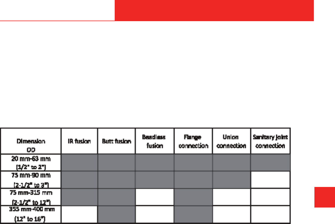
655 Andover Street, Lawrence, MA 02148 • Tel: 800-343-3618, 781-321-5409
Fax: 800-787-6861 • https://www.asahi-america.com • Email: [email protected]
MECHANICAL CONNECTIONS
Connection Technology
Connection systems have to be designed to avoid
any kind of stresses. Stresses, which may arise from
GLႇHUHQFHVLQWHPSHUDWXUHEHWZHHQLQVWDOODWLRQDQG
operation conditions, must be kept as low as possible by
taking appropriate measures as described in the section
design and calculation guide.
'HSHQGLQJRQWKHSLSHGLPHQVLRQWKHIROORZLQJ
connection systems are applicable:
E
GENERAL INSTALLATION
MECHANICAL CONNECTION
ASAHI/AMERICA
Rev. 2013-A
E-21
Welding Machines
8WLOL]HSURYHQZHOGLQJWHFKQLTXHVIRUWKHMRLQLQJRI
FRPSRQHQWVRQO\DSSURYHGZHOGLQJPDFKLQHVVKRXOG
be used. The application of non-approved welding
techniques can result in reduced joint quality in both
strength and purity. In addition, welding parameters
should be recorded for every performed welding. A print-
RXWODEHOZLWKVLJQL¿FDQWZHOGLQJLQIRUPDWLRQLVUHTXLUHG
to identify and evaluate every welding joint.
The utilized welding machines and appliances must
FRUUHVSRQGWRWKHJXLGHOLQHVRIWKH'96
In general, the following facts should be considered for
welding high purity thermoplastic piping systems:
• Application of suitable and approved welding
machines
• $SSOLFDWLRQRIWUDLQHGDQGFHUWL¿HGSHUVRQQHO
Welding Personnel
The quality of the welded joints depends on the
TXDOL¿FDWLRQRIWKHZHOGHUWKHVXLWDELOLW\RIWKHPDFKLQHV
and appliances, as well as the compliance of the welding
guidelines. The welding joint can be tested and inspected
by destructive and/or visual methods.
The welding work must be supervised. The type and
scope of supervision must be agreed on by the parties. It
is recommended to record the procedure data in welding
protocols or on data carriers.
Within the scope of the quality assurance, it is
recommended to produce and test samples of joints
before beginning and during the welding works.
(YHU\ZHOGHUKDVWREHWUDLQHGDQGPXVWKDYHYDOLGSURRI
RITXDOL¿FDWLRQ7KHLQWHQGHGDSSOLFDWLRQUDQJHPD\EH
GHFLVLYHIRUWKHNLQGRITXDOL¿FDWLRQ7KHZHOGLQJH[DP
FHUWL¿FDWHDFFRUGLQJWR'96LQWKHJURXSV,
UHV,LQFRQMXQFWLRQZLWKWKHFRPSOHPHQWLQJWUDLQLQJ
FHUWL¿FDWHLVVXHGE\DQDXWKRUL]HGWUDLQLQJLQVWLWXWH
or by the particular machine manufacturer, is valid as
TXDOL¿FDWLRQSURRI
Figure E-32. Applicable connection systems

655 Andover Street, Lawrence, MA 02148 • Tel: 800-343-3618, 781-321-5409
Fax: 800-787-6861 • https://www.asahi-america.com • Email: [email protected]
• Consideration of the prescribed welding guidelines
(parameters)
• 3HUIRUPDQFHRIWKHZHOGLQJSURFHVVLQWKHFOHDQURRP
area
• Complete control and documentation of the
performed welding operations
The design of a system should consider installation
conditions, such as space and environment conditions.
Based on the above criteria, the choice of welding
technique is crucial for a successful installation. The
installation should be planned to fabricate assemblies
and subassemblies to reduce the amount of welds
FRQGXFWHGLQUHVWULFWHGFRQ¿QHGORFDWLRQV
Measures Before the Welding Operation
The welding zone must be protected against bad
ZHDWKHULQÀXHQFHVHJPRLVWXUHZLQG89UDGLDWLRQ
DQGWHPSHUDWXUHVEHORZ)&RUKLJKHUWKDQ
)&,ILWLVHQVXUHGE\VXLWDEOHPHDVXUHV
(e.g., preheating, tent, or heating) that a component
WHPSHUDWXUHVXႈFLHQWIRUZHOGLQJFDQEHNHSWDVIDU
as the welder is not hindered in his handling, work may
be carried out at any outside temperature. If necessary,
an additional proof must be provided by carrying out
sample welds under the mentioned conditions.
If the welding products are heated up unevenly under
WKHLQÀXHQFHRIVXQVKLQHDWHPSHUDWXUHFRPSHQVDWLRQ
in the area of the welding joint can be reached by
covering.
The pipe ends should be closed during the welding
process.
The joining areas of the parts to be welded must be
clean (free from dirt, oil, shavings, or other residues) and
in a straight-cut, planed surface condition before start
the welding process.
On applying any of these methods, keep the welding
DUHDFOHDURIÀH[XUDOVWUHVVHVHJFDUHIXOVWRUDJHXVH
of pipe supports, etc.).
Welding Joint Evaluation
The control of the welding joint quality on site should
EHSHUIRUPHGRQO\E\FHUWL¿HGSHUVRQQHOZLWKSURSHU
NQRZOHGJHRIWKHZHOGLQJWHFKQLTXH'LႇHUHQWWHVWV
DFFRUGLQJWR'96JXLGHOLQHVPD\EHSHUIRUPHG
E
GENERAL INSTALLATION
MECHANICAL CONNECTION
ASAHI/AMERICA
Rev. 2013-A
E-22
• 9LVXDOWHVWRIWKHZHOGLQJMRLQW'96
• Tensile test for the determination of the short-term
ZHOGLQJIDFWRU'96SDUW
• Bending test for the determination of the bending
DQJOH'96SDUW
• 3UHVVXUHWHVWRQWKHLQVWDOOHGSLSHOLQHDFFRUGLQJWR
'96SDUWVXSSOHPHQW',1
Flange
Flanging and AV Gaskets
:KHQEROWLQJDÀDQJHFRQQHFWLRQLWLVUHTXLUHGWR
WLJKWHQWKHEROWVLQDVSHFL¿HGSDWWHUQDQGWRDUHTXLUHG
VSHFL¿FDWLRQ$VDKL$PHULFDRႇHUVDOLQHRIORZWRUTXH
$9JDVNHWVLQVL]HV´±´IRUVLQJOHZDOOSLSH
FRQQHFWLRQV7KHVHJDVNHWVRႇHUDXQLTXHGRXEOH
convex ring design that gives optimum sealing with
RQHWKLUGWKHWRUTXHRIDFRPPRQÀDWJDVNHWVHDO7KH
gaskets are available in the following materials:
• (3'0
• 39')ERQGHGRYHU(3'0
• 7HÀRQ
®
RYHU(3'0
They are available in both standard and high-purity
JUDGH37)(DQG39')ERQGHGJDVNHWVDUHSURGXFHG
in a proprietary laminating process for bonding to
(3'07KHXVHRIWKHUXEEHUEDFNLQJSURYLGHVJUHDWHU
elasticity for lower bonding torques.
Detail of Gasket
:KHQWLJKWHQLQJDÀDQJHWKHWRUTXHUDWLQJLVGHSHQGHQW
RQWKHJDVNHWXVHG)RUWKH$9JDVNHWVHH7DEOH(IRU
the recommended tightness. In addition, follow the star
SDWWHUQVKRZQ)LJXUH(ZKHQWLJKWHQLQJ&RQGXFW
WZRRUWKUHHSDVVHVWLJKWHQLQJWKHÀDQJHXQLIRUPO\
)LQLVKE\GRLQJDFLUFXODUSDVVWRFKHFNWKHWRUTXH
values. Always use a torque wrench when tightening a
ÀDQJH$FRPPRQPLVWDNHZKHQWLJKWHQLQJDÀDQJHLV
WRVTXHH]HLWDVWLJKWO\DVSRVVLEOHKRZHYHUWKLVDFWLRQ
will damage the gasket and eventually lead to reduced
HODVWLFLW\DQGOHDNDJH'RQRWWLJKWHQEH\RQGWKHUDWLQJ

655 Andover Street, Lawrence, MA 02148 • Tel: 800-343-3618, 781-321-5409
Fax: 800-787-6861 • https://www.asahi-america.com • Email: [email protected]
Table E-8. Recommended Bolt Torque for AV
Gaskets (lbs.)
Figure E-33. Torque pattern
%XWWHUÀ\9DOYHV
Most Asahi/America piping systems are produced
to metric dimensions according to ISO standards.
+RZHYHU$VDKL$PHULFDEXWWHUÀ\YDOYHVDUHSURGXFHG
according to iron pipe size dimensions. The outcome
LVWKDWLQFHUWDLQVL]HVWKHGLVNRIWKHEXWWHUÀ\YDOYH
can meet interference with the inside pipe wall
ZKHQRSHQLQJ7KHLQWHUIHUHQFHLVW\SLFDOLQ6'5
SRO\SURS\OHQHV\VWHPVLQ´RUODUJHUDQG6'5
SRO\SURS\OHQHLQ´RUODUJHU,Q39')V\VWHPVWKH
HႇHFWLV´±´LQ6'5DQG´RUODUJHULQ6'5
V\VWHPV3RO\SURS\OHQHVWXEVLQWKHLQWHUIHULQJ
dimensions are always beveled at the factory to avoid
WKLVLVVXH39')VWXEHQGVPRXQWHGIRUEXWWHUÀ\YDOYH
installation must be ordered special from Asahi/America.
39')VWXEVDUHQRWDXWRPDWLFDOO\VXSSOLHGZLWKD
beveled end for other reasons. Contact Asahi/America
IRUVSHFLDOSDUWQXPEHUVRQ39')EHYHOHGVWXEHQGV
Flange Connections of Piping Systems
,ISLSHMRLQWVDUHFRQQHFWHGE\PHDQVRIÀDQJHVWKH
following guidelines must be adhered to:
E
GENERAL INSTALLATION
MECHANICAL CONNECTION
ASAHI/AMERICA
Rev. 2013-A
E-23
• Aligning of parts
Before applying initial stress on the screw, the
sealing faces have to be on an aligned plane, parallel
WRHDFKRWKHUDQG¿WWLJKWWRWKHVHDOLQJ8QGHUDQ\
FLUFXPVWDQFHVWKHÀDQJHFRQQHFWLRQVKRXOGQRW
draw near to the occurring tensile stress.
• Tightening of screws
The length of the screws has to be chosen so that
WKHVFUHZWKUHDGSRVVLEO\ÀXVKHVZLWKWKHQXW
Washers have to be placed at the screw head and
also at the nut. The connecting screws have to be
screwed in with a torque key (for torque values see
www.agru.at).
*HQHUDOO\LWLVUHFRPPHQGWREUXVKRYHUWKHWKUHDG
HJZLWKPRO\EGHQXPVXO¿GHVRWKDWWKHWKUHDG
UXQVHDVLO\IRUDORQJHURSHUDWLRQWLPH)RUWKH
selection of sealing material, the chemical and
thermal resistance has to be considered.
Adhesive Joints
$GKHVLYHMRLQWVZLWKSRO\ROH¿QHVDUHQRWDSSOLFDEOH7KH
achieved strength values range extremely below the
minimum requirements for adhesive joints in practice.
Tri clamp
7ULFODPSVRWKHUZLVHNQRZQDVVDQLWDU\¿WWLQJVDUHD
common form of mechanical joining of pipes in high
purity applications. A typical tri clamp connection
consists of two ferrules, a gasket with raised groove, and
RQHRIVHYHUDOW\SHVRIFODPSV7KHFRPELQHGÀDQJH
DQGJDVNHWGRQRWLPSHGHWKHÀRZRIÀXLGVWKRXJKWKH
pipe. The clamping system can be easily removed when
XVLQJDIROGRYHUKLQJHGFODPS3ODVWLFWULFODPSVDUH
designed to allow connection to existing stainless steel,
DQGVDQLWDU\V\VWHPV3OHDVHFRQVXOW$VDKL$PHULFDIRU
additional information about thermoplastics for use in
pharmaceutical.
Thread
In general, threaded connections are not recommended
for high pressure thermoplastic piping systems. If
thermoplastic pipe is threaded, the pressure rating is
GHUDWHGVLJQL¿FDQWO\,QFHUWDLQLQVWDQFHVDQLQVWDOOHU
may choose to thread the system. Recommendations
for threading plastic piping have been developed by the
See product data sheet.

655 Andover Street, Lawrence, MA 02148 • Tel: 800-343-3618, 781-321-5409
Fax: 800-787-6861 • https://www.asahi-america.com • Email: [email protected]
3ODVWLF3LSLQJ,QVWLWXWH,WVKRXOGEHQRWHGWKDWFHUWDLQ
Asahi/America systems with thinner walls simply cannot
be threaded. In addition, metric pipe systems, even
with thick pipe walls, cannot be threaded because the
RXWVLGHGLDPHWHUVDUHQRWWKHVDPHDV,36SLSHPDNLQJ
the threads too short in height.
Only pipe that has a wall thickness greater than
6FKHGXOHVKRXOGEHWKUHDGHG2QO\SLSHGLHVWKDWDUH
FOHDQVKDUSDQGVSHFL¿FDOO\GHVLJQHGIRUSODVWLFSLSLQJ
should be used. If a vise is used to restrain the pipe
during the cutting, exercise caution to avoid scratching
or deforming the pipe. Wooden plugs inserted in the
pipe ends can reduce this risk.
Before cutting threads, the pipe must be deburred of all
sharp edges. A die stock with a proper guide that will
start and go on square to the pipe axis should be used.
The use of cutting oil should be kept to a minimum.
Once the threads are cut, they should be seated with
37)(WDSH
In most cases, the use of threading pipe can be avoided
altogether by the use of molded male and female
DGDSWHUV7KHVH¿WWLQJVKDYHEHHQGHVLJQHGDQG
SURGXFHGWRSURYLGHDIXOOSVLSUHVVXUHUDWLQJDW
&)7KHPDOHDQGIHPDOHDGDSWHUVDGGUHVV
the need to connect to existing pipe systems or
equipment without derating the system. The use of these
¿WWLQJVZHOGHGWRWKHSLSHLVUHFRPPHQGHGLQVWHDGRI
attempting to thread pipe.
Asahi/America does not recommend threading or
WKUHDGHG¿WWLQJVPDGHRI+'3(
Weatherability/UV
:HDWKHU(ႇHFWV
3RO\SURS\OHQH+'3(DQG39')DUHUHVLVWDQWWRQHDUO\
HYHU\HႇHFWRIZHDWKHU+RZHYHUWKH\GLႇHURQRQH
important characteristic: resistance to ultraviolet light
GHJUDGDWLRQ39')LVDOPRVWFRPSOHWHO\XQDႇHFWHGE\
89OLJKW+'3(ZLWKLWVEODFNDGGLWLYHLVUHVLVWDQWWR
89OLJKWDVLV3RO\)OR
®
black polypropylene. Standard
SRO\SURS\OHQHIURP$VDKL$PHULFDLVD(XURSHDQ
JUD\SRO\SURS\OHQHWKDWLVDႇHFWHGDVWKHHQHUJ\IURP
ultraviolet radiation initiates a chemical reaction in the
SRO\PHU1DWXUDOSRO\SURS\OHQHLVQRW89UHVLVWDQW
7KHUHDFWLRQEHWZHHQSRO\SURS\OHQHJUD\DQG89
radiation only takes place at the surface to shallow
depths measured in minute fractions of an inch. The
E
GENERAL INSTALLATION
MECHANICAL CONNECTION
ASAHI/AMERICA
Rev. 2013-A
E-24
molecules at the surface of the plastic are permanently
altered to form a complex formation of various
chemicals, such as polypropylene-type formations. A
noticeable chalky-yellow appearance ensues, which
results in a slight reduction in impact strength. This
HႇHFWZLOORQO\EHFRPHQRWLFHDEOHXSRQSURORQJHG
exposure, and it will not continue to progress if the
XOWUDYLROHWVRXUFHLVUHPRYHG7KHHႇHFWFDQEH
measured after a prolonged period of time as a slight
increase in tensile strength, a slight increase in elastic
modulus, and a minor decrease in impact strength. The
degradation only occurs to a shallow depth, although
in time the chemically altered surface molecules may
VOLJKWO\ÀDNHRႇ7KLQZDOOHGSRO\SURS\OHQHSLSH¿WWLQJV
should be protected against ultraviolet light penetration
if placed in an outdoor environment. Some of the
various methods include painting, providing a “shield,”
or taping/wrapping the pipe. In order to paint the piping,
SRO\SURS\OHQHPXVW¿UVWUHFHLYHDFRDWLQJRIDVXLWDEOH
primer to allow the acrylic lacquer to be applied. The
primer can be applied by brush to small diameter pipes
and sprayed onto larger diameter pipes. Then, a suitable
paint can be selected and applied in a similar fashion.
It is advisable to strictly adhere to the manufacturer’s
instructions concerning safe operating practices when
applying the selected paint.
A thin-walled insulation-type shield or rigid vapor jacket
EDUULHUFDQHOLPLQDWHWKHHႇHFWVRIXOWUDYLROHWOLJKW$WKLQ
aluminum shield should provide all the protection that is
necessary.
A third method includes covering the piping with tape.
A recommended type of tape is called “TapeCoat” and
LVPDGHE\7DSH&RDW,QFRI(YDQVWRQ,/7KLVWDSH
VKRXOGEHDSSOLHGZLWKSHUFHQWRYHUODSDQGZKHQ
properly applied, it will completely protect the piping
against ultraviolet attack.
Chlorine and Chlorinated Hydrocarbon
Installations
:KHQ39')LVXVHGWRWUDQVSRUWFKORULQHRUFKORULQDWHG
hydrocarbons, special precautions should be taken if the
possibility of a reaction is suggested by the application.
In certain post-chlorination pipe lines, downstream in a
bleached paper process (chlorine dioxide reactor, for
instance), there exists a small amount of spent reactants
that ordinarily would not proceed to completion.
+RZHYHULWKDVEHHQVKRZQWKDWXOWUDYLROHWOLJKWIURP
VXQOLJKWRUÀXRUHVFHQWOLJKW¿[WXUHVPD\RႇHUHQRXJK
energy to initiate this reaction to completion.

655 Andover Street, Lawrence, MA 02148 • Tel: 800-343-3618, 781-321-5409
Fax: 800-787-6861 • https://www.asahi-america.com • Email: [email protected]
In the process, free-radical chlorine is released
instantaneously, and there is a tendency for some
substitution of chlorine molecules for hydrogen in the
polymer chain. As this happens, stress cracks may
appear in the pipe wall through a mechanism that is not
yet completely understood, and the system may fail.
7KHUHIRUHLWLVUHTXLUHGWRSURWHFWDQ\39')V\VWHP
from the possibility of ultraviolet light propagation
from reactions involving the generation of free-radical
chlorine. One method of providing this protection is
through the same method of taping described in the
previous section for protecting polypropylene piping from
ultraviolet attack.
Union
Unions of Piping Systems
If pipe joints made out of thermoplastics are connected
by means of unions, the following regulations have to be
adhered to:
• )RUDYRLGLQJLPSHUPLVVLEOHORDGVDWLQVWDOODWLRQ
unions with round sealing rings should be applied
• The union nut should be screwed manually or
by means of a pipe band wrench (common pipe
wrenches should not be used)
• 3UHYHQWWKHDSSOLFDWLRQRIXQLRQVDWDUHDVZLWK
bending stresses in the piping systems
7LSWKUHDGVHDORQO\ZLWK7HÀRQ
®
do not use hemp
E
GENERAL INSTALLATION
MECHANICAL CONNECTION
ASAHI/AMERICA
Rev. 2013-A
E-25

655 Andover Street, Lawrence, MA 02148 • Tel: 800-343-3618, 781-321-5409
Fax: 800-787-6861 • https://www.asahi-america.com • Email: [email protected]
E
GENERAL INSTALLATION
MECHANICAL CONNECTION
ASAHI/AMERICA
Rev. 2013-A
E-26

655 Andover Street, Lawrence, MA 02148 • Tel: 800-343-3618, 781-321-5409
Fax: 800-787-6861 • https://www.asahi-america.com • Email: [email protected]
Section F
SPECIAL SYSTEM
CONSIDERATIONS
Contents
High Purity .....................F-2
Industrial ...................... F-6
Double Contained ............... F-9
Ventilation .................... F-10
Compressed Air ............... F-12
F-1
ASAHI/AMERICA
Rev. 2013-A

655 Andover Street, Lawrence, MA 02148 • Tel: 800-343-3618, 781-321-5409
Fax: 800-787-6861 • https://www.asahi-america.com • Email: [email protected]
HIGH PURITY
High Purity System Design
A pure water system comprised of PVDF or
polypropylene is similar to most chemical feed systems.
The critical factor in a pure system is to design it in a
continuous moving loop without dead-legs to avoid the
possibility of microorganism growth.
6\VWHPVVKRXOGDOVREHVL]HGWRKDYHWXUEXOHQWÀRZ
as part of the method of inhibiting bacteria growth.
PVDF and PP systems are ideally suited for pure water
as they have extremely smooth inner surfaces that
reduce particle generation and inhibit sites for bacteria
to adhere to and proliferate. In addition, PVDF and PP
systems have low extractables; therefore, the water
being transported is not contaminated.
In designing a thermoplastic high purity water system,
the following items need to be considered:
• Materials of construction
• Operating parameters
• System sizing
• Thermal expansion
• Minimizing dead-legs
• System monitoring
• Hanging
• Welding methods
• Other considerations
Materials of Construction
PVDF is the premier material for high purity water
systems. PVDF has been used in ultrapure water
systems for over 25 years because it is superior
to materials such as stainless steel or PVC. PVDF
FRPELQHVH[FHOOHQWVXUIDFH¿QLVKZLWKORZH[WUDFWDEOHV
to provide the highest quality piping material for the
application. In addition to its purity attributes, PVDF is
also available in a variety of components and welding
methods that are well-suited for UPW applications.
PVDF is a crystalline material that can withstand high
pressures. However, the nature of PVDF requires
special planning and handling during the installation.
These types of requirements are now commonplace
on the market and are accepted as standard operating
methods. PVDF is recommended for the service of the
strictest applications that require low bacteria counts
and virtually undetectable levels of metal ions.
F
SYSTEM CONSIDERATIONS
HIGH PURITY
F-2
For applications less stringent in water quality level,
SRO\SURS\OHQHLVDQH[FHOOHQWDOWHUQDWLYH33RႇHUV
excellent surface smoothness, as well as low extractable
levels as compared to stainless steel. Polypropylene
systems are thermally fused together, eliminating the
use of glues, which will continue to leach into a water
system for extended periods of time. PP is an extremely
weldable material, making fusion joints simple and
reliable. For more information on PP, consult Section B.
The third alternative is E-CTFE. This material, also
known as Halar
®
, provides superior surface even
compared to PVDF. Its extraction levels are also similar
to those of PVDF. Halar
®
is a very ductile material,
making its use and welding methods extremely reliable.
E-CTFE is normally only available in certain sizes
and does have some pressure limitations at higher
temperature. Halar
®
has become the preferred material
for tank lining applications.
Operating Parameters
Because thermoplastic systems have varying ratings
DWGLႇHUHQWWHPSHUDWXUHVLWLVLPSRUWDQWWRGHVLJQD
system around all of the parameters to which it will be
VXEMHFWHG$VD¿UVWSDVVYHULI\WKHIROORZLQJRSHUDWLQJ
parameters:
• Continuous operating temperature
• Continuous operating pressure
• Media and concentration
By knowing the above parameters, thermoplastic
pipe systems can be selected. Compare the actual
conditions to the allowable ratings of the material being
selected for the job. It is important to predict elevated
temperatures, as thermoplastics have reduced pressure
UDWLQJVDWKLJKHUWHPSHUDWXUHV9DOYHVVKRXOGEHYHUL¿HG
separately from a piping system in terms of temperature
and pressure, as certain styles and brands of valves
have lower ratings than the pipe system. Finally, if the
media is not water, a chemical compatibility check
should be conducted with the manufacturer.
After verifying the standard operating conditions, it
is necessary to examine other operations that might
DႇHFWWKHSLSLQJ7KHIROORZLQJLVDVDPSOHRILWHPVWR
investigate prior to specifying a material.
• Will there be spikes in temperature or pressure?
• Is there a cleaning operation that the piping will be
exposed to?
ASAHI/AMERICA
Rev. 2013-A

655 Andover Street, Lawrence, MA 02148 • Tel: 800-343-3618, 781-321-5409
Fax: 800-787-6861 • https://www.asahi-america.com • Email: [email protected]
• If yes, what is the cleaning agent? What
temperature will the cleaning be conducted at?
• Will the system be exposed to sunlight or other
sources of UV?
Each of the above questions should be answered, and
the desired material should be checked for suitability
based on the above factors, as well as any others that
might be unique to the system in question.
System Sizing
It is well-known that high purity water systems are
GHVLJQHGWRRSHUDWHLQDFRQWLQXRXVO\ÀRZLQJORRSWR
prevent stagnant water in the system. Stagnant water
FDQSUROLIHUDWHWKHJURZWKRIEDFWHULDDQGELR¿OP7KH
pattern and design of the loop will vary depending on the
facility requirements.
7KHÀRZUDWHLQWKHV\VWHPLVLPSRUWDQWIRUGHWHUPLQLQJ
the pipe diameter size. In a pure water system, elevating
ÀRZYHORFLWLHVLVUHFRPPHQGHGWRUHGXFHWKHSRVVLELOLW\
of bioadhesion to the pipe wall or welded surfaces.
0DQ\VSHFL¿FDWLRQVZLOOVWDWHWKDWWKHÀRZVKRXOGEH
VHWDWDPLQLPXPRI¿YHIHHWSHUVHFRQGZKLFKZLOO
DOZD\VEHDWXUEXOHQWÀRZDWWKLVYHORFLW\+RZHYHU
a more sensible approach may be to review the
5H\QROGV1XPEHURIWKHV\VWHPWRHQVXUHWKDWWKHÀRZ
is turbulent. Use of the Reynolds Number may reduce
waste caused by the oversizing of pumps to overcome
excessive pressure drops due to unnecessarily high
velocities.
Because many HP systems are now produced
from high-quality Purad
®
PVDF, high velocities
LQDFRQWLQXRXVO\ÀRZLQJV\VWHPPD\QRWEHDV
necessary. High velocities are generally accomplished
by undersizing the pipe diameter, which is directly
proportional to increased pressure drops. In fact, high
minimum velocities are detrimental to the ability of a
system to deliver adequate point-of-use pressure during
peak demand conditions. Therefore, using cleaner,
smoother material such as PVDF is desirable for design
and operation.
Sizing Laterals
A pure water system and an ultra pure water system
will be made of main loop branches known as laterals.
It is important in design to not dead-end laterals and
HQVXUHWKHUHLVDOZD\VÀRZPRYHPHQWLQWKHPDLQDQG
LQWKHODWHUDO6\VWHPVDUHGHVLJQHGZLWKGLႇHUHQWORRS
F
SYSTEM CONSIDERATIONS
HIGH PURITY
F-3
FRQ¿JXUDWLRQVWRDFFRPPRGDWHWKHQHHGVRISURGXFWLRQ
However, all laterals must be designed for continuous
ÀRZDQGVKRXOGIHHGXQXVHGZDWHUEDFNLQWRWKHUHWXUQ
line.
For supply laterals feeding multiple tools, the lateral
needs to be sized based on an acceptable pressure
drop. A general rule of thumb is two psig per 100 feet.
Consideration of point-of-use water consumption, length,
and frequency of demand must be factored into the
sizing process of the lateral.
Sizing Mains
Main trunk lines are sized using the demand for water
by the tools plus the tool and return lateral minimum
ÀRZV7RROGHPDQGFDQEHFDOFXODWHGE\WDNLQJWKH
DYHUDJHÀRZGHPDQGDQGPXOWLSO\LQJLWE\WRWR
accommodate for peak demand. This should be based
on the tool manufacturer’s parameters.
The return lines should be sized for minimal pressure
drop when the tool demand is at a minimum, which will
correspond to maximum bypass at the end of a main
pressure control station.
Thermal Expansion
Typically, Purad
®
and PolyPure
®
systems are designed
for ambient or cold DI water. In these cases, because
the systems operate continuously and are normally
inside a fairly constant temperature building, the need
to compensate for thermal expansion is not required.
Although, it is an important factor that should be
reviewed on each and every installation design.
Hot DI systems that normally operate at temperatures
RI)WR)&WR&GHSHQGLQJRQWKH
water usage, require a more complex design. PVDF
systems can be used in hot water applications and
applications where the temperature is cyclical. These
systems require analysis of the thermal expansion
HႇHFWV,QPRVWFDVHVWKHXVHRIH[SDQVLRQVRႇVHWV
and proper hanging techniques is all that is required to
ensure a proper design.
Hot DI systems also reduce the rigidity of thermoplastic
piping systems, which, in turn, decreases the support
spacing between pipe hangers. In smaller dimensions,
it is recommended to use continuous support made of
some type of channel or split plastic pipe.
Finally, the use of hangers as guides and anchors
becomes important. Certain hangers should be used
ASAHI/AMERICA
Rev. 2013-A

655 Andover Street, Lawrence, MA 02148 • Tel: 800-343-3618, 781-321-5409
Fax: 800-787-6861 • https://www.asahi-america.com • Email: [email protected]
as guides to allow the pipe to move back and forth in-
line, while other hangers should be anchoring locations
used to direct the expansion into the compensating
device. The anchors and hangers should be designed
to withstand the end load generated by the thermal
expansion.
Minimize Dead-Legs
The term dead-leg refers to a stagnant zone of water
in the system. Dead-legs are normally formed in the
EUDQFKRIDWHHWKDWLVFORVHGRႇZLWKDYDOYH6HH
Figure F-1.
Figure F-1. Dead-legs due to poor design
A rule of thumb in designing a system is to keep all
dead-legs to a maximum of six internal pipe diameters
LQOHQJWK7KHWXUEXOHQWÀRZLQWKHPDLQWUXQNOLQHZLOO
FUHDWHDVLJQL¿FDQWDPRXQWRIPRYHPHQWWRNHHSWKH
leg moving and prevent bacteria from adhering to the
pipe wall. However, the Purad
®
system allows designers
to avoid dead-legs altogether with the advent of
7GLDSKUDJPYDOYHVDQG]HURGHDGOHJ¿WWLQJV
7YDOYHVVHH)LJXUH)WDNHWKHSODFHRIDWHH
reducer, and diaphragm valve by combining all three into
one component. T-valves reduce the quantity of welds
in a system as well. By using a T-valve, branch lines can
EHVKXWRႇDWDQ\WLPHZLWKRXWFUHDWLQJDGHDGOHJDQG
WXUQHGEDFNRQZLWKRXWDQH[WHQVLYHÀXVKSURFHGXUH
Figure F-2. T-valve eliminates dead-leg
Dead legs in a system can be found in more than
F
SYSTEM CONSIDERATIONS
HIGH PURITY
F-4
just branch lines. Often, the introduction of a gauge,
measurement device, and/or sampling valve can create
a dead leg. Because it is not recommended to tap into
the side of a PVDF pipe for safety reasons, gauges are
installed using tees and caps, as shown in Figure F-3.
Figure F-3. Dead-leg due to improper
instrument installation
%HFDXVHWKHVHWHHFRQ¿JXUDWLRQVDUHQDUURZLQ
diameter, they create a dead-leg in the branch where
microorganism growth can be initiated. The use of
LQVWUXPHQWDWLRQ¿WWLQJVHOLPLQDWHVGHDGOHJVZKLOHDFWLQJ
as a safe adapter for gauges or sample valves. See
Figure F-4.
)LJXUH)3URSHUXVHRILQVWUXPHQW¿WWLQJWRDYRLG
dead space. Can be used with gauge
guard.
The insertion of a resistivity probe can also be a
possible source for dead legs. Because most probe
PDQXIDFWXUHUVUHFRPPHQGWKDWÀXLGÀRZVGLUHFWO\DW
the probe, they are often situated in the leg of a tee,
and the tee acts as a 90° elbow. Because most probes
DUHVXSSOLHGDVD´137¿WWLQJRUVDQLWDU\DGDSWHU
there is the necessity to weld reducers onto the tee leg
to accommodate the sensor, which will create a dead
]RQH$VLPSOH¿WWLQJWKHSUREHDGDSWHUFRQYHQLHQWO\
eliminates the need for reducers and shortens the leg of
the tee. See Figure D-5. Probe adapters are available in
ASAHI/AMERICA
Rev. 2013-A

655 Andover Street, Lawrence, MA 02148 • Tel: 800-343-3618, 781-321-5409
Fax: 800-787-6861 • https://www.asahi-america.com • Email: [email protected]
all sizes and pressure ratings.
Figure F-5. Proper adapter setups
High Purity Installation
Installing a high purity system properly requires
preplanning. The installation is more than the welding
of components. It requires the proper environment,
material inventory, welding equipment, tools, and
thorough training.
General rules on installation
• The quality level of the materials should be
PDLQWDLQHGIURPGHOLYHU\WRWKH¿QLVKHGSURMHFW
• No smoking or eating is allowed during working
time.
• There should be incoming control of material and
marking of quality level according to the user’s
standards of marking and labeling.
• Do not touch the inner surface of any kind of pipe
component, not even in gloves.
Welding environment
Asahi/America does not set requirements for proper
welding environments. As the installer, it is necessary to
choose the environment based on the installation type,
timing, or quality goal. In all cases, the environment
for welding should be monitored to ensure that the
WHPSHUDWXUHLVLQWKHUDQJHRI)WR)&WR
&7KHKXPLGLW\VKRXOGQRWH[FHHGSHUFHQW,I
using IR fusion, wind must be avoided.
All Purad
®
, PP-Pure
®
, and PolyPure
®
components
are manufactured and packaged in a clean room
environment. Great care is taken to ensure that they
arrive on the project site in protective packaging to
maintain their purity. To be consistent, it is ideal to
conduct welds in a clean or clean room environment.
Particles, dust, or dirt in the air will adhere to the pipe
during the welding process. To reduce contamination
in the system, as many welds as possible should be
F
SYSTEM CONSIDERATIONS
HIGH PURITY
F-5
conducted in a clean environment. A class ISO 5 or ISO
URRPLVSHUIHFWO\VXLWDEOH3RUWDEOHVW\OHFOHDQURRPV
PDNHIRUDQHႈFLHQWVHWXSZKHQFRQGXFWLQJDOORIWKH
welds on site.
Figure F-6. Portable cleanroom
Within the clean zone, it is recommended to build spool
SLHFHV7KHVL]HDQGFRQ¿JXUDWLRQLVGHSHQGHQWRQWKH
DELOLW\WRVDIHO\WUDQVSRUWLWWRLWV¿QDOGHVWLQDWLRQ7KH
HQGVRIWKHVSRROSLHFHVVKRXOGEHSUHSDUHGIRU¿QDO
connection once in the pipe rack. In smaller dimensions,
2'PPWR2'PP´±´WKHHQGVVKRXOGEH
¿WWHGZLWKXQLRQVRUVDQLWDU\¿WWLQJVWRUHGXFHZHOGVLQ
WKHSLSHUDFNDVWKH\DUHPRUHGLႈFXOW
,QVL]HVODUJHUWKDQ2'PP´LWLVUHFRPPHQGHG
WREXLOGVSRROSLHFHVZLWKÀDQJHFRQQHFWLRQV'RLQJWKLV
DYRLGVKDYLQJWRFRQGXFWGLႈFXOWIXVLRQZHOGVLQWLJKW
ORFDWLRQV)ODQJHGVSRROSLHFHVDOVRRႇHUWKHEHQH¿WRI
being able to make changes later.
If welding in a clean room or clean environment, remove
WKHRXWHUEDJLQDVWDJLQJDUHDDQGVWRUHWKH¿WWLQJ
inside the clean room in the single bag until ready for
XVH,WLVUHFRPPHQGHGWRVWRUHWKH¿WWLQJVLQSODVWLF
bins within the clean room instead of using a cardboard
box within a clean environment. Label bins by size and
¿WWLQJVW\OH
PolyPure
®
¿WWLQJVVKRXOGEHOHIWLQWKHLUEDJDQGEURXJKW
into the clean zone as is. If for some reason the outside
of the bag is contaminated, it should be wiped down with
IPA prior to entering the clean zone. Valves should be
handled in the same manner.
When ready to transport the pipe into the clean zone,
open the outer cap on the HDPE protection tube of the
PVDF UHP pipes. Place the tube next to the clean zone
entry, and slide the pipe directly from the tube into the
clean room. This will eliminate the need to wipe down
the bag prior to entry. In the clean room, remove the
ASAHI/AMERICA
Rev. 2013-A

655 Andover Street, Lawrence, MA 02148 • Tel: 800-343-3618, 781-321-5409
Fax: 800-787-6861 • https://www.asahi-america.com • Email: [email protected]
single bag if ready for immediate usage. If stored in the
clean environment, it is preferred to leave the pipe in its
original packaging.
Place the double bagged PP-Pure
®
pipe next to the
clean zone entry. Open the second bag, and slide the
single bagged pipe into the clean room. Remove the
single bag if ready for immediate usage.
PolyPure
®
pipes can remain in their shipping packaging
until ready for use or transported into the fabrication
clean room.
When ready for welding, remove all packaging and
caps. Remember to save the caps for sealing the ends
of prefabricated spool pieces.
Training
An ultra pure water or chemical system is a critical
utility within a plant’s operation. An unplanned shutdown
can prove to be more costly than the water piping
construction itself. One bad weld can cause hours
RIUHSDLUDQGIUXVWUDWLRQDVZHOODVVLJQL¿FDQWORVV
of revenue. For these reasons, it is critical to receive
WUDLQLQJDWWKHWLPHRIMREVWDUWXSDQGWRXVHFHUWL¿HG
personnel throughout the course of a project. Tool
operation is only one of several factors in a thorough
training course. Operators, inspectors, and managers
need to understand the physical nature of the material:
how to properly handle it, how to inspect welds, how
to identify potential problems, how to properly maintain
HTXLSPHQWDQG¿QDOO\KRZEHVWWRWLHLQWRDOLQHDQGWHVW
it.
All of the above topics are discussed during AGRU’s
FHUWL¿HGWUDLQLQJVHVVLRQV)RUWKHLQVWDOODWLRQRID
high-purity system, the following training sessions are
available:
• 7RRORSHUDWRUWUDLQLQJDQGFHUWL¿FDWLRQ
• Quality control inspection
INDUSTRIAL
Single Wall Chemical Pipe System Design
When properly designing a single wall pipe system for
the transport of chemicals, several factors need to be
reviewed.
A properly designed thermoplastic system will provide
years of reliable service without the headaches of
F
SYSTEM CONSIDERATIONS
INDUSTRIAL
F-6
corrosion problems.
At the time of design, consider and plan for the following
items:
• Materials of construction
• Thermal expansion
• System sizing
• UV considerations
• Insulation
• Hanging
• Welding methods
Materials of Construction
7KH¿UVWDQGIRUHPRVWLWHPLQDQ\V\VWHPGHVLJQPHWDO
RUWKHUPRSODVWLFLVWKHPHGLDWKDWZLOOEHUXQQLQJ
through the pipes and parameters of operation. Using
accurate data for the system design will transfer to years
of reliable operation. When considering the system
design, answer the following questions:
:KDWLVDUHWKHFKHPLFDOVWREHLQFRQWDFWZLWKWKH
system?
• What are the chemical concentrations?
• What temperature will the system operate at?
• What pressure will the system operate at?
:KDWLVWKHÀRZRIWKHPHGLDLQWKHV\VWHP"
By answering these questions, the proper material
of construction can be selected for the project. To assist
in the material selection, refer to the chemical resistance
tables on our web site. A thermoplastic system’s
ratings for temperature and pressure are based on
water. The addition of certain chemicals will add stress
to the system and may reduce the recommended
operating parameters. For less aggressive chemicals,
the resistance tables on our web site are perfectly
suitable. For more aggressive chemicals or mixtures of
chemicals, the manufacturer of the pipe system should
be consulted.
After verifying the standard operating conditions, it
is necessary to examine other operations that might
DႇHFWWKHSLSLQJ7KHIROORZLQJLVDVDPSOHRILWHPVWR
investigate prior to specifying a material.
• Will there be spikes in temperature or pressure?
• Is there a cleaning operation that the piping will be
exposed to?
• If yes, what is the cleaning agent? What temperature
will the cleaning be conducted at?
• Will the system be exposed to sunlight or other
ASAHI/AMERICA
Rev. 2013-A

655 Andover Street, Lawrence, MA 02148 • Tel: 800-343-3618, 781-321-5409
Fax: 800-787-6861 • https://www.asahi-america.com • Email: [email protected]
sources of UV?
Each of the these questions should be answered and
the desired material should be checked for suitability
based on these factors, as well as any others that might
be special to the system in question.
Finally, in addition to verifying the temperature, pressure,
and media with the thermoplastic pipe material, it is also
necessary to verify other components in the system,
such as valves, gaskets, valve seat and seals, etc.
These should be examined in the same manner as the
pipe material.
Thermal Expansion
Based on your operating criteria, thermal expansion
must be considered. For systems maintained at
consistent temperatures, compensation for thermal
HႇHFWVPD\QRWEHUHTXLUHG,WLVKRZHYHULPSRUWDQWWR
review all aspects such as the operating environment.
Is it outdoors where it will be exposed to changing
weather? Is the system spiked with a high temperature
FOHDQLQJVROXWLRQ":LOOWKHV\VWHPUXQDWDVLJQL¿FDQWO\
higher temperature than the installation temperature?
The occurrence of any thermal change in a plastic
system will cause the material to expand or contract. As
DQH[DPSOHRIWKHHႇHFWSRO\SURS\OHQHZLOOJURZURXJKO\
RQHLQFKIRUHYHU\OLQHDUIHHWDQGǻ7
Thermoplastic systems can be used in hot applications
and applications where the temperature is cyclical; it
MXVWUHTXLUHVDQDO\VLVRIWKHWKHUPDOH[SDQVLRQHႇHFWV
Section C walks through the steps of calculating thermal
expansion, end loads, and expansion compensating
GHYLFHV,QPRVWFDVHVWKHXVHRIH[SDQVLRQVRႇVHWV
and proper hanging techniques are all that is required to
ensure a proper design.
Hot systems also reduce the rigidity of thermoplastic
piping, which, in turn, decreases the support spacing
between pipe hangers. In smaller dimensions, it is
recommended to use continuous support made of some
type channel or split plastic pipe.
Finally, the use of hangers as guides and anchors
becomes important. As the design procedures in Section
C indicates, certain hangers should be used as guides
to allow the pipe to move back and forth in-line, while
other hangers should be anchoring locations used to
direct the expansion into the compensating device. The
anchors and hangers should be designed to withstand
F
SYSTEM CONSIDERATIONS
INDUSTRIAL
F-7
the end load generated by the thermal expansion.
)LJXUH)LVDQH[DPSOHRIDQDQFKRUW\SHUHVWUDLQW
¿WWLQJWKDWLVDYDLODEOHIURP$VDKL$PHULFD
)LJXUH)5HVWUDLQW¿WWLQJ
For calculation of allowed stresses and design of
expansion compensation devices, refer to Section C,
Engineering Theory and Design Considerations.
System Sizing
,Q6HFWLRQ&WKHUHLVDGHWDLOHGGLVFXVVLRQRQÀXLG
G\QDPLFVDQGGHWHUPLQDWLRQRIÀRZUDWHVDQGSUHVVXUH
drops. When using any thermoplastic with a hazardous
FKHPLFDOLWLVUHFRPPHQGHGWRPDLQWDLQÀRZUDWHV
below a velocity of 5 ft/second. High velocities can lead
to water hammer in the event of an air pocket in the
system. Water hammer can generate excessive
pressures that can damage a system. For safety
reasons, high velocities should be avoided.
In addition, high velocities also mean added pressure
drop, which, in turn, increases demand on the pump.
,IWKHÀRZYHORFLW\LVQRWUHTXLUHGLWLVUHFRPPHQGHG
to size a system with minimal pressure drop. It is also
recommended to oversize a design to allow for future
expansion or chemical demand. Once a system is in
SODFHLWLVGLႈFXOWWRDGGFDSDFLW\WRLW
UV Considerations
All thermoplastic materials react to the exposure of UV
GLႇHUHQWO\39')DQG(&7)(PDWHULDOVDUHDOPRVW
completely UV-resistant over the course of its design
life. However, certain chemicals containing Cl anions
exposed to UV light can create a free-radical Cl, which
will attack the PVDF pipe wall. For more information
on these chemicals, refer to UV Exposure and
Weatherability later in this section.
Polypropylene is not UV stable. In direct exposure to
VXQOLJKWLWZLOOEUHDNGRZQ7KHHႇHFWFDQEHVHHQLQD
ASAHI/AMERICA
Rev. 2013-A

655 Andover Street, Lawrence, MA 02148 • Tel: 800-343-3618, 781-321-5409
Fax: 800-787-6861 • https://www.asahi-america.com • Email: [email protected]
noticeable color change in the pipe. In a pigmented PP
system, the color change will actually create a protective
shield on the outer layer of the pipe and prevent further
degradation. For PP pipes with a wall thickness greater
WKDQ´WKHHႇHFWRI89LVUHGXFHGDQGFDQEHXVHG
outside. However, it is still recommended to protect
it from UV exposure for added safety. Natural PP will not
self create a UV shield as the pigment PP does;
therefore, UV protection is required all the time on
natural PP systems.
Other materials, such as HDPE, may or may not be UV
stabilized. PE containing carbon black are generally UV
stable and can handle direct exposure. Other HDPE
materials may require protection. Use of protection
should be based on the individual grade of the
polyethylene. Consult the manufacturer for details.
Insulation
Insulation is a good method of protecting a pipe system
from UV exposure, as well as providing required
insulation for the system or media being transported. A
VHULRXVGLႇHUHQFHEHWZHHQSODVWLFDQGPHWDOLVSODVWLF¶V
thermal properties. A metal pipe system will quickly
take the temperature of the media being transported.
$V\VWHPFDUU\LQJDPHGLDDW)&ZLOOKDYH
DQRXWHUZDOOWHPSHUDWXUHFORVHWRRUDW)&
In contrast, thermoplastics have an inherent insulating
property that maintains heat inside the pipe better than
a metal system. The advantage is that a plastic pipe has
better thermal properties, which translates into improved
RSHUDWLQJHႈFLHQFLHVDQGUHGXFHGLQVXODWLRQWKLFNQHVV
Hanging
See Section C for hanging details and proper placement
GLVWDQFHV6LQFHSODVWLFUHDFWVGLႇHUHQWO\WKDQPHWDO
varying hanger styles are required. The designer of a
system should specify the exact hanger and location
and not leave this portion up to the installer.
Welding Methods
The system designer should specify the welding method
WREHXVHGLQDQ\JLYHQSURMHFW$VDKL$PHULFDRႇHUV
several choices for joining PVDF and PP together. The
choice of a particular method should be based on the
following concerns:
• Installation location
• Size range
F
SYSTEM CONSIDERATIONS
INDUSTRIAL
F-8
• System complexity
PVDF can be installed using butt fusion, IR fusion,
socket fusion, and beadless HPF fusion. All methods
are proven in chemical systems and each has its own
advantages. Polypropylene is weldable using butt,
,5RUVRFNHWIXVLRQ,QDGGLWLRQ$VDKL$PHULFDRႇHUV
electrofusion couplings for PP that are ideal for repairs.
(OHFWURIXVLRQ33FRXSOLQJVPD\KDYHUHGXFHGFKHPLFDO
UHVLVWDQFH&RQVXOWIDFWRU\(&7)(FDQEH
welded using butt or IR fusion. It is recommended to
assemble Halar
®
with IR fusion, as special heating
elements are required for welding Halar
®
with
conventional butt fusion equipment.
Socket fusion is ideal for small, simple, low-cost
V\VWHPV,QVPDOOGLDPHWHUV´±´VRFNHWIXVLRQ
can be done quite easily with a hand-held welding plate
and a few inserts. With just a limited amount of practice,
an installer can make safe and reliable joints. For larger
dimensions, up to a maximum of 4”, bench-style socket
fusion equipment is available for keeping joints aligned.
For systems that have larger dimensions above 4”,
butt and IR fusion make a logical choice. Butt fusion is
available in every pipe size made available by Asahi/
America. Welding can take place in a variety of climates
DQGFRQGLWLRQV,QDGGLWLRQEXWWIXVLRQRႇHUVWKHZLGHVW
variety of welding equipment options. Tools are available
for bench welding, trench welding, and welding in the
rack, making it completely versatile for almost
all applications. Refer to Section F for guidance in tool
selection.
IR fusion is available for welding 1/2” to 10”. IR is an
extension of the butt fusion method. The operation is
the same with the exception that material being joined is
not in contact with the heat source. Rather, the material
is brought in close to the heating element and the heat
UDGLDWHVRႇWRWKHFRPSRQHQWV7KHDGYDQWDJHRIWKLV
method for chemical systems is the elimination
of molten material sticking to the heat source.
IR fusion is better suited for indoor applications. IR
fusion equipment is highly sophisticated, providing the
operator with detailed information on the weld process
and quality. For critical applications with dangerous
media, IR fusion may be best suited due to the quality
assurance built into each piece of equipment.
ASAHI/AMERICA
Rev. 2013-A

655 Andover Street, Lawrence, MA 02148 • Tel: 800-343-3618, 781-321-5409
Fax: 800-787-6861 • https://www.asahi-america.com • Email: [email protected]
DOUBLE CONTAINED
Design of the Double Containment Piping
System
Installation System
In comparison with the installation of a single pipe,
there are possible changes in length in the installation
of the double containment piping system that are due
to thermal expansion or contraction, and they require
special attention. The temperature changes of the inside
DQGRXWVLGHSLSHVFDQEHGLႇHUHQWRUHYHQRSSRVLWH
based on the distance between the pipes. This can
lead to considerable length expansions between the
pipes. If it cannot be detected, constructive stress will
be developed, which is an additional demand on the
SLSHOLQHV2QHFDQGLVWLQJXLVKEHWZHHQWKUHHGLႇHUHQW
GHVLJQV\VWHPV¿[HGÀH[LEOHDQGLPSHGHG
Fixed System
The inside, outside, and surrounding area of the pipe
DUH¿[HGWRJHWKHUE\GRJERQHVRQHDFKGLUHFWLRQDO
change. A length expansion of the inside or outside pipe
is not possible.
Advantages:
• Low expenses
• Little area needed
Disadvantages:
• +LJK'RJERQHIRUFHVQRWHWKH¿[LQJGHPDQG
Figure F-8. Fixed system design
8QLPSHGHG+HDW([SDQVLRQÀH[LEOHV\VWHP
F
SYSTEM CONSIDERATIONS
DOUBLE CONTAINED
F-9
The inside and outside pipes are installed so that a
length expansion from both pipes, and even among
each other, can happen. In terms of the planning, it
needs to be considered that the length expansion of the
inside pipe takes place in the outside pipe.
Advantages:
• Applicable for higher operating temperatures
• Low stress of the double containment piping system
because of free expansion
Disadvantages:
• Higher expenses
• Often need large area because of the compensation
elbow
Figure F-9. Unimpeded heat expansion design
System with Impeded Heat Expansion
7KHLQVLGHDQGRXWVLGHSLSHVDUH¿[HGWRJHWKHUE\
dog bones. The length expansion of the whole double
FRQWDLQPHQWSLSHOLQHZLOOEHSLFNHGXSWKURXJKVXႈFLHQW
PHDVXUHVFRPSHQVDWRUVWUDLJKW7KLVPHWKRGLVRQO\
sensible when the inside and outside pipes are made
out of the same material and few temperature changes
occur between the inside and outside pipes.
Advantages:
• Low expenses
• 8VXDOO\ORZ¿[LQJH[SHQVHV
Disadvantages:
• High stress in the double containment piping system
• Often need large area because of the compensation
elbow
ASAHI/AMERICA
Rev. 2013-A

655 Andover Street, Lawrence, MA 02148 • Tel: 800-343-3618, 781-321-5409
Fax: 800-787-6861 • https://www.asahi-america.com • Email: [email protected]
Figure F-10. Impeded heat expansion design
VENTILATION
Ventilation System Design
Thermoplastic materials have begun to be used for
ventilation applications. A thermoplastic vent system
provides many features that standard sheet metal
cannot in terms of functionality, ease of installation, and
corrosion resistance.
In designing a thermoplastic water system, the following
items need to be considered:
• Materials of construction
• Operating parameters
• Codes
• Layout recommendations
• Thermal expansion
• UV exposure
• Hanging
• Welding methods
Materials of Construction
For the construction of ventilation systems,
Asahi/America provides the ProVent
®
system.
ProVent
®
components are available in polypropylene
3UR9HQW
DQG39')3XUDG9HQW
®
7KHV\VWHPLV
GHVLJQHGVSHFL¿FDOO\IRUWKHYHQWLODWLRQDQGWUDQVSRUW
of hazardous fumes and potentially corrosive gases.
%RWKSRO\SURS\OHQHDQG39')RႇHUGLႇHUHQWUHVLVWDQFH
WRFKHPLFDODSSOLFDWLRQVWKDWVKRXOGEHYHUL¿HGSULRUWR
purchase.
Operating Parameters
The ProVent
®
system is available in multiple wall
thicknesses in polypropylene. The selection of a material
pressure rating should be based on the following criteria:
F
SYSTEM CONSIDERATIONS
VENTILATION
F-10
• Operating temperature
• Media to be transported
• Operating pressure, positive or negative
• Economics
• 5HTXLUHG¿UHFRGHV
• Size to be installed
By evaluating the previous parameters, the proper
system can be chosen. In many applications,
polypropylene will more than exceed the needs of the
system; however, if the media to be transported is at an
elevated temperature, PVDF may be required.
In general, PP systems are available in a larger
selection of sizes and pressure rating options. Refer to
Asahi/America’s ProVent
®
Dimensional Guide for the
availability of components.
Codes
For designing a ventilation system, the most pertinent
FRGHLVSUREDEO\WKH¿UHFRGHRUWKHQHHGIRU)DFWRU\
0XWXDO)0DSSURYDO3UR9HQW
®
systems made of
polypropylene can be installed according to FM
UHJXODWLRQVDQGWKH¿QDOLQVWDOOHGSURGXFWZLOOPHHW)0
requirements. The use of PP in systems requiring FM
approval will require the use of an internal sprinkler head
V\VWHP,QFDVHRID¿UHWKHVSULQNOHUV\VWHPZRXOG
eliminate the possibility of the vent system spreading the
¿UH
There are sprinkler systems on the market that are
VSHFL¿FDOO\GHVLJQHGIRUWKLVDSSOLFDWLRQDQGWKH\
dramatically reduce the installation labor, as well as
the required sprinkler head inspection process after
LQVWDOODWLRQ)LJXUH)VKRZVGHWDLOVRIDW\SLFDOÀH[LEOH
VSULQNOHUKHDGDQGWKHPRXQWLQJFRPSRQHQWRႇHUHGE\
Asahi/America.
)LJXUH)'HWDLORIDÀH[LEOHVSULQNOHUKHDGDQG
mounting component
PuradVent
®
PVDF is a material that is considered self-
H[WLQJXLVKLQJ39')KDVVLJQL¿FDQWO\EHWWHUVPRNHDQG
ASAHI/AMERICA
Rev. 2013-A

655 Andover Street, Lawrence, MA 02148 • Tel: 800-343-3618, 781-321-5409
Fax: 800-787-6861 • https://www.asahi-america.com • Email: [email protected]
ÀDPHUDWLQJVWKDQPRVWRWKHUWKHUPRSODVWLFPDWHULDOV
39')PDWHULDORႇHUHGE\$VDKL$PHULFDLVDQ)0
approved material, according FM 4910 Standards.
Contact Asahi/America for further information on
installation requirements for PVDF systems. In addition,
$VDKL$PHULFDKDVWKHWHVWUHVXOWVRQ¿OHIRUPXOWLSOH
VPRNHDQGÀDPHVWDQGDUGVIRUERWKSRO\SURS\OHQHDQG
PVDF.
In short, there may be a need or requirement for
internal closed-head sprinklers in a ProVent
®
system if
combustible materials can accumulate inside the pipe
line.
Layout Recommendations
Ventilation systems are often the most custom designed
of any pipe system in the factory. They are large in
diameter and generally need to be connected to multiple
HTXLSPHQWYHQWV$VDKL$PHULFDRႇHUVDZLGHUDQJHRI
standard components for assembling a system.
However, many systems cannot be accomplished using
standard components. A skilled installer can make
VSHFLDOIDEULFDWLRQVLQWKH¿HOGWRDFFRPSOLVKWKHOD\RXW
requirement of a system. In addition, Asahi/America
can design and prefabricate pipe systems and ship
them ready for installation. Figure F-12 shows details
of a component that could not be made with standard
¿WWLQJVEXWFDQHDVLO\EHSURGXFHGLQ$VDKL$PHULFD¶V
fabrication shop and shipped to the job site ready to be
installed.
Figure F-12. Asahi/America prefabricated assembly
For more information on fabrication assistance, contact
Asahi/America’s Engineering Department.
F
SYSTEM CONSIDERATIONS
VENTILATION
F-11
Thermal Expansion
Based on a system’s operating criteria, thermal
expansion must be considered. For systems maintained
at consistent temperatures, compensation for thermal
HႇHFWVPD\QRWEHUHTXLUHG+RZHYHULWLVLPSRUWDQWWR
review all aspects of the operating environment. Certain
questions should be considered, such as:
• Is the system outdoors where it will be exposed to
changing weather?
• Is the system spiked with a high-temperature
cleaning solution?
• :LOOWKHV\VWHPUXQDWDVLJQL¿FDQWO\KLJKHU
temperature than the installation temperature?
The occurrence of any thermal change in a plastic
system will cause the material to expand or contract. As
DQH[DPSOHRIWKHHႇHFWSRO\SURS\OHQHZLOOJURZURXJKO\
RQHLQFKIRUHYHU\OLQHDUIHHWDW)¨7
Ventilation systems will often reach an equilibrium with
the temperature of the ambient environment. Therefore,
if the pipe is hung in a ceiling where the temperature
will vary in the summer and winter, the change in
WHPSHUDWXUHWKDWPRVWDႇHFWVWKHSLSHPD\EHGXHWR
the ambient temperature change rather than media
temperature change. This is almost always the case in
systems installed outdoors.
ProVent
®
systems can be used in hot applications and
in applications where the temperature is cyclical; it just
UHTXLUHVDQDO\VLVRIWKHWKHUPDOH[SDQVLRQHႇHFWV,Q
PRVWFDVHVWKHXVHRIH[SDQVLRQVRႇVHWVDQGSURSHU
hanging techniques is all that is required to ensure a
proper design.
Hot systems also reduce the rigidity of thermoplastic
piping, which, in turn, decreases the support spacing
between pipe hangers. In smaller dimensions, it is
recommended to use continuous support made of some
type of channel or split plastic pipe. Review hanging
requirements that are based on the actual operating
temperatures.
Finally, the use of hangers as guides and anchors
becomes important. Certain hangers should be used
as guides to allow the pipe to move back and forth in-
line, while other hangers should be anchoring locations
used to direct the expansion into the compensating
device. The anchors and hangers should be designed
to withstand the end-load generated by the thermal
expansion.
ASAHI/AMERICA
Rev. 2013-A

655 Andover Street, Lawrence, MA 02148 • Tel: 800-343-3618, 781-321-5409
Fax: 800-787-6861 • https://www.asahi-america.com • Email: [email protected]
UV Exposure
As a rule, PVDF material is UV resistant and can be
installed in direct exposure to sunlight without protection.
In certain applications with chlorine content, this may not
be true. Free-radical chlorine can cause a breakdown of
PVDF when exposed to UV light. For these applications,
it is best to protect the pipe by wrapping or insulating it.
Contact Asahi/America for information on chemicals that
FDQFDXVHWKLVHႇHFW
Polypropylene is not 100 percent UV stable. Over time,
the outer surface of a standard gray polypropylene
pipe will change color and become brittle. The surface
becomes chalky to the touch. Generally, if the surface
LVOHIWXQWRXFKHGWKHHႇHFWRIWKH89FKDQJHZLOOVWRS
and not continue through the pipe. A pipe with a heavy
wall thickness may not require protection, as the change
ZLOORQO\RFFXURQWKHRXWHUPRVWVXUIDFH7KHHႇHFWRQ
the mechanical strength of the pipe will be minimal.
However, most ventilation systems operate at low
pressures and use thin-walled pipe for cost savings.
Therefore, the ProVent
®
PP, in most cases, should be
wrapped or protected from UV exposure.
Hanging
%HFDXVHSODVWLFUHDFWVGLႇHUHQWO\WKDQPHWDOYDU\LQJ
hanger styles are required. The designer of a system
should specify the exact hanger and location instead of
leaving this portion up to the installer.
Consult Asahi/America’s Engineering Department for the
hanging distance required on ProVent
®
systems.
Welding Methods
There are several options for installing a ProVent
®
system. Many projects will incorporate two or three
GLႇHUHQWMRLQLQJWHFKQLTXHV
The methods are:
• Conventional butt fusion
• Hot air welding
• Extrusion welding
ProVent
®
is made to the same outer wall dimensions
',16WDQGDUGVDVDOORWKHUSRO\SURS\OHQHDQG39')
SLSHV\VWHPVRႇHUHGE\$VDKL$PHULFD7KHVDPH
butt fusion equipment and methodology can be used
to assemble these systems. Butt fusion provides full
SUHVVXUHUDWHGZHOGVDQGRႇHUVDKLJKGHJUHHRI
reliability for ventilation welding. However, depending
F
SYSTEM CONSIDERATIONS
VENTILATION
F-12
on the size of pipe and location of the welds, butt fusion
can be cumbersome. Conducting a weld in a ceiling of
´SLSHZLOOEHGLႈFXOWDQGZLOOFRQVXPHDVLJQL¿FDQW
amount of time to lift the pipe, the tool, and an operator
into position.
In many cases, it is recommended to prefabricate
a system on the ground or in a workshop and then
FRQGXFW¿QDODVVHPEO\XVLQJÀDQJHFRQQHFWLRQV,Q
DGGLWLRQWRXVLQJÀDQJHFRQQHFWLRQVIRU¿QDOKRRN
XSFRXSOLQJVDQGVOLSÀDQJHVFDQEHXVHG7KHVH
components can be hot air welded or extrusion welded,
depending on the size of the pipe and the required
system operating pressure.
+DQGZHOGLQJKRWDLURUH[WUXVLRQZHOGLQJLV
a convenient method for welding in place or in
prefabrication. The following is a detail of a slip
coupling being hand welded. This method, while
convenient, is highly reliant on an operator’s skill. Hot
air welding is simple and requires minimal practice to
EHFRPHSUR¿FLHQWKRZHYHUH[WUXVLRQZHOGLQJLVPRUH
complicated, and a more extensive training course is
required. Once these skills are mastered, they will prove
highly useful during installation. It is recommended on
all ProVent
®
projects to buy at least one hot air welding
tool, as there is always a need for it.
Figure F-13. Weld option
COMPRESSED AIR
Compressed Air System Design
See Air-Pro
®
product guide on www.asahi-america.com
ASAHI/AMERICA
Rev. 2013-A

655 Andover Street, Lawrence, MA 02148 • Tel: 800-343-3618, 781-321-5409
Fax: 800-787-6861 • https://www.asahi-america.com • Email: [email protected]
Section G
DESIGN &
PRESSURE TESTING
Contents
Single Contained ................G-2
Double Contained ...............G-6
G-1
ASAHI/AMERICA
Rev. 2013-A

655 Andover Street, Lawrence, MA 02148 • Tel: 800-343-3618, 781-321-5409
Fax: 800-787-6861 • https://www.asahi-america.com • Email: [email protected]
SINGLE CONTAINED
Single Wall Chemical Pipe
System Design
When properly designing a single wall pipe system for
the transport of chemicals, several factors need to be
reviewed. A properly designed thermoplastic system will
provide years of reliable service without the headaches
of corrosion problems. At the time of design, consider
and plan for the following items:
• Materials of construction
• Thermal expansion
• System sizing
• UV considerations
• Insulation
• Hanging
• Welding methods
Materials of Construction
7KH¿UVWDQGIRUHPRVWLWHPLQDQ\V\VWHPGHVLJQPHWDO
or thermoplastic) is the media that will be running
through the pipes and parameters of operation. Using
accurate data for the system design will transfer to years
of reliable operation. When considering the system
design, answer the following questions:
• :KDWFKHPLFDOVZLOOEHLQFRQWDFWZLWKWKHV\VWHP"
• :KDWDUHWKHFKHPLFDOFRQFHQWUDWLRQV"
• $WZKDWWHPSHUDWXUHZLOOWKHV\VWHPRSHUDWH"
• $WZKDWSUHVVXUHZLOOWKHV\VWHPRSHUDWH"
• :KDWLVWKHÀRZRIWKHPHGLDLQWKHV\VWHP"
By answering these questions, the proper material
of construction can be selected for the project. A
thermoplastic system’s ratings for temperature and
pressure are based on water. The addition of certain
chemicals will add stress to the system and may
reduce the recommended operating parameters. For
less aggressive chemicals, use the printed resistance
tables available on our web site. For more aggressive
chemicals or mixtures of chemicals, the manufacturer of
the pipe system should be consulted.
After verifying the standard operating conditions, it is
QHFHVVDU\WRH[DPLQHRWKHURSHUDWLRQVWKDWPLJKWDႇHFW
the piping. The following is a sample of questions to
investigate prior to specifying a material.
• :LOOWKHUHEHVSLNHVLQWHPSHUDWXUHRUSUHVVXUH"
G
DESIGN & PRESSURE TESTING
SINGLE CONTAINED
G-2
• Is there a cleaning operation that the piping will be
H[SRVHGWR"
• ,I\HVZKDWLVWKHFOHDQLQJDJHQW"$WZKDW
WHPSHUDWXUHZLOOWKHFOHDQLQJEHFRQGXFWHG"
• Will the system be exposed to sunlight or other
VRXUFHVRI89"
Each of these questions should be answered, and the
desired material should be checked for suitability based
on these factors as well as any others that might be
unique to the system in question.
Finally, in addition to verifying the temperature, pressure,
and media within the thermoplastic pipe material, it
is also necessary to verify other components in the
system, such as valves, gaskets, valve seat and seals,
etc. These should be examined in the same manner as
the pipe material.
Thermal Expansion
Based on your operating criteria, thermal expansion
may need to be considered. For systems maintained
at consistent temperatures, compensation for thermal
HႇHFWVPD\QRWEHUHTXLUHG+RZHYHULWLVLPSRUWDQWWR
review all aspects of the operating environment, such
as:
• Is it outdoors where the pipe will be exposed to
FKDQJLQJZHDWKHU"
• Is the system spiked with a high temperature
FOHDQLQJVROXWLRQ"
• :LOOWKHV\VWHPUXQDWDVLJQL¿FDQWO\KLJKHU
WHPSHUDWXUHWKDQWKHLQVWDOODWLRQWHPSHUDWXUH"
The occurrence of any thermal change in a plastic
system will cause the material to expand or contract. As
DQH[DPSOHRIWKHHႇHFWSRO\SURS\OHQHZLOOJURZURXJKO\
RQHLQFKIRUHYHU\OLQHDUIHHWDQG¨7
Thermoplastic systems can be used in hot applications
and applications where the temperature is cyclical; it just
UHTXLUHVDQDO\VLVRIWKHWKHUPDOH[SDQVLRQHႇHFWV,Q
PRVWFDVHVWKHXVHRIH[SDQVLRQVRႇVHWVDQGSURSHU
hanging techniques is all that is required to ensure a
proper design.
Hot systems also reduce the rigidity of thermoplastic
piping, which, in turn, decreases the support spacing
between pipe hangers. In smaller dimensions, using
continuous supports made of some type of channel or
split plastic pipe is recommended.
ASAHI/AMERICA
Rev. 2013-A

655 Andover Street, Lawrence, MA 02148 • Tel: 800-343-3618, 781-321-5409
Fax: 800-787-6861 • https://www.asahi-america.com • Email: [email protected]
Finally, the use of hangers as guides and anchors
becomes important. Certain hangers should be used
as guides to allow the pipe to move back and forth in-
line, while other hangers should be anchoring locations
used to direct the expansion into the compensating
device. The anchors and hangers should be designed to
withstand the thermal end load generated by the thermal
expansion. Figure G-1 is an example of an anchor type
UHVWUDLQW¿WWLQJWKDWLVDYDLODEOHIURP$VDKL$PHULFD
)LJXUH*5HVWUDLQW¿WWLQJ
System Sizing
When using any thermoplastic with a hazardous
FKHPLFDOLWLVUHFRPPHQGHGWRPDLQWDLQÀRZUDWHV
EHORZDYHORFLW\RIIHHWVHFRQG+LJKYHORFLWLHVFDQ
lead to water hammer in the event of an air pocket in
the system. Water hammer can generate excessive
pressures that can damage a system. For safety
reasons, high velocities should be avoided.
In addition, high velocities also mean added pressure
drop, which, in turn, increases demand on the pump.
,IWKHÀRZYHORFLW\LVQRWUHTXLUHGLWLVUHFRPPHQGHG
to size a system with minimal pressure drop. It is also
recommended to oversize a design to allow for future
expansion or chemical demand. Once a system is in
SODFHLWLVGLႈFXOWWRDGGFDSDFLW\WRLW
UV Considerations
All thermoplastic materials react to the exposure of UV
GLႇHUHQWO\39')DQG(&7)(PDWHULDOVDUHDOPRVW
completely UV resistant over the course of their design
life. However, certain chemicals containing Cl anions
exposed to UV light can create a free radical Cl, which
ZLOODWWDFNWKH39')SLSHZDOO
3RO\SURS\OHQHLVQRW89VWDEOH,QGLUHFWH[SRVXUHWR
VXQOLJKWLWZLOOEUHDNGRZQ7KHHႇHFWFDQEHVHHQLQD
QRWLFHDEOHFRORUFKDQJHLQWKHSLSH,QDSLJPHQWHG33
system, the color change will actually create a protective
shield on the outer layer of the pipe and prevent further
GHJUDGDWLRQ)RU33SLSHVZLWKDZDOOWKLFNQHVVJUHDWHU
G
SINGLE CONTAINED
G-3
WKDQ´WKHHႇHFWRI89LVUHGXFHGVRWKH\FDQEH
used outside. However, it is still recommended to protect
the pipes from UV exposure for added safety. Natural
33ZLOOQRWVHOIFUHDWHD89VKLHOGDVWKHSLJPHQW33
does; therefore, UV protection is required all the time on
QDWXUDO33V\VWHPV
2WKHUPDWHULDOVVXFKDV+'3(PD\RUPD\QRWEH89
VWDELOL]HG3(FRQWDLQLQJFDUERQEODFNLVJHQHUDOO\89
VWDEOHDQGFDQKDQGOHGLUHFWH[SRVXUH2WKHU+'3(
materials may require protection. Use of protection
should be based on the individual grade of the
polyethylene. Consult the manufacturer for details.
Insulation
,QVXODWLRQLVDQHႇHFWLYHPHWKRGRISURWHFWLQJDSLSH
system from UV exposure, as well as providing required
insulation for the system or media being transported. A
VHULRXVGLႇHUHQFHEHWZHHQSODVWLFDQGPHWDOLVSODVWLF¶V
thermal properties. A metal pipe system will quickly
take the temperature of the media being transported.
$V\VWHPFDUU\LQJDPHGLDDW)&ZLOOKDYH
DQRXWHUZDOOWHPSHUDWXUHFORVHWRRUDW)&
In contrast, thermoplastics have an inherent insulating
property that maintains heat inside the pipe better than
a metal system. The advantage is that a plastic pipe has
better thermal properties, which translates into improved
RSHUDWLQJHႈFLHQFLHVDQGUHGXFHGLQVXODWLRQWKLFNQHVV
Hanging
%HFDXVHSODVWLFUHDFWVGLႇHUHQWO\WKDQPHWDOYDU\LQJ
hanger styles are required. The designer of a system
should specify the exact hanger and location instead of
leaving this portion up to the installer.
Welding Methods
The system designer should specify the welding method
WREHXVHGLQDQ\JLYHQSURMHFW$VDKL$PHULFDRႇHUV
VHYHUDOFKRLFHVIRUMRLQLQJ39')DQG33WRJHWKHU7KH
choice of a particular method should be based on the
following concerns:
• Installation location
• Size range
• System complexity
39')FDQEHLQVWDOOHGXVLQJEXWWIXVLRQ,5IXVLRQ
VRFNHWIXVLRQDQGEHDGOHVV+3)IXVLRQ$OOPHWKRGV
are proven in chemical systems, and each has its
RZQDGYDQWDJHV3RO\URS\OHQHLVZHOGDEOHXVLQJEXWW
,5RUVRFNHWIXVLRQ,QDGGLWLRQ$VDKL$PHULFDRႇHUV
HOHFWURIXVLRQFRXSOLQJVIRU33WKDWDUHLGHDOIRUUHSDLUV
DESIGN & PRESSURE TESTING
ASAHI/AMERICA
Rev. 2013-A

655 Andover Street, Lawrence, MA 02148 • Tel: 800-343-3618, 781-321-5409
Fax: 800-787-6861 • https://www.asahi-america.com • Email: [email protected]
(OHFWURIXVLRQ33FRXSOLQJVPD\KDYHUHGXFHGFKHPLFDO
resistance. Consult factory.) E-CTFE can be welded
using butt or IR fusion. It is recommended to assemble
Halar
®
with IR fusion, as special heating elements are
required for welding Halar
®
with conventional butt fusion
equipment.
Socket fusion is ideal for small, simple, low-cost
V\VWHPV,QVPDOOGLDPHWHUV´´VRFNHWIXVLRQ
can be done quite easily with a hand-held welding plate
and a few inserts. With just a limited amount of practice,
an installer can make safe and reliable joints. For larger
GLPHQVLRQVXSWRDPD[LPXPRI´EHQFKVW\OHVRFNHW
fusion equipment is available for keeping joints aligned.
)RUV\VWHPVWKDWKDYHGLPHQVLRQVDERYH´EXWWDQG
IR fusion make a logical choice. Butt fusion is available
LQHYHU\SLSHVL]HPDGHDYDLODEOHE\$VDKL$PHULFD
Welding can take place in a variety of climates and
FRQGLWLRQV,QDGGLWLRQEXWWIXVLRQRႇHUVWKHZLGHVW
variety of welding equipment options. Tools are available
for bench welding, trench welding, and welding in
the rack, making it completely versatile for almost all
applications.
,5IXVLRQLVDYDLODEOHIRUZHOGLQJ´WR´,5LVDQ
extension of the butt fusion method. The operation is the
same with the exception that the material being joined is
not in contact with the heat source. Rather, the material
is brought in close to the heating element, and the heat
UDGLDWHVRႇWRWKHFRPSRQHQWV7KHDGYDQWDJHRIWKLV
method for chemical systems is the elimination of molten
material sticking to the heat source.
IR fusion is better suited for indoor applications. IR
fusion equipment is highly sophisticated, providing the
operator with detailed information on the weld process
and quality. For critical applications with dangerous
media, IR fusion may be best suited due to the quality
assurance built into each piece of equipment.
Burial Practices for Single Wall Piping
When designing the underground burial of thermoplastic
SLSLQJERWKVWDWLFHDUWKORDGVDQGOLYHORDGVIURPWUDႈF
must be taken into account. The static load is the weight
of the column of soil on the piping. The actual static
load that the pipe is subjected to is dependent on many
factors: the type of soil, the compaction of the soil, the
width and detail of the trench, and the depth that the
pipe is buried. The deeper the burial, the higher the load.
Burial of Single Wall Piping
G
SINGLE CONTAINED
G-4
Live loads decrease radially from the point at the
surface from which they are applied. Live loads will
KDYHOLWWOHHႇHFWRQSLSLQJV\VWHPVH[FHSWDWVKDOORZ
GHSWKV3RO\SURS\OHQHSRO\HWK\OHQHDQG39')DUH
ÀH[LEOHFRQGXLWV$FFRUGLQJWRDEDVLFUXOHRIWKXPEDW
OHDVWWZRSHUFHQWRIGHÀHFWLRQFDQEHDFKLHYHGZLWKRXW
any structural damage or cracking. When analyzing
a system for its capability of withstanding earth and
OLYHORDGLQJGHÀHFWLRQXQGHUSURSRVHGFRQGLWLRQVLV
FRPSDUHGWRPD[LPXPDOORZDEOHGHÀHFWLRQ¿YHSHUFHQW
IRU33DQG3(DQGWKUHHSHUFHQWIRU39')DQGWKHQ
the adequacy is judged.
Determination of Earth Loads
7KHPHWKRGIRUGHWHUPLQLQJHDUWKORDGVRIDÀH[LEOH
conduit is the Marston Theory of loads on underground
conduits. From the theory, it is concluded that the load
RQDULJLGFRQGXLWLVJUHDWHUWKDQRQDÀH[LEOHFRQGXLW
7RGHWHUPLQHWKHHDUWKORDGRQDÀH[LEOHFRQGXLWWKH
Marston equation for earth loads is used. The ratio
RIWKHORDGRQDULJLGFRQGXLWWRWKHORDGRQDÀH[LEOH
conduit is:
The theory implies that a trench width twice the width
of a conduit being buried will result in a load on a rigid
FRQGXLWWZLFHWKDWRIDÀH[LEOHFRQGXLW)LJXUH*
displays the dimensions indicated in Equation G-1.
DESIGN & PRESSURE TESTING
ASAHI/AMERICA
Rev. 2013-A

655 Andover Street, Lawrence, MA 02148 • Tel: 800-343-3618, 781-321-5409
Fax: 800-787-6861 • https://www.asahi-america.com • Email: [email protected]
Figure G-2. Example of underground installation
7KHORDGFRHႈFLHQW&
d
) depends on the ratio of
WKHKHLJKWRIWKH¿OOWRWKHWUHQFKZLGWKDQGFDQEH
determined from the following equation:
From Equation G-3 , a larger load can be expected at
increasing widths. As trench width increases, this load
increases at a decreasing rate until a value as prism
load is attained. For most applications, this value can be
calculated as follows:
And prism load, expressed in terms of soil pressure, is
as follows:
G
SINGLE CONTAINED
G-5
3ULVPORDGLQJLVWKHPD[LPXPDWWDLQDEOHORDGLQD
burial situation and represents a conservative design
DSSURDFK'XHWRWKHIDFWWKDWIURVWDQGZDWHUDFWLRQLQ
a soil may dissipate frictional forces of the trench, the
long-term load may approach the prism load. Therefore,
it is recommended that this load be considered when
designing an underground thermoplastic piping system.
6LPSOL¿HG0HWKRGIRU%XULDO'HVLJQ
To properly determine the feasibility of thermoplastic
piping systems in a buried application, follow the steps
below. These steps will provide the proper design to
resist static soil loads.
Step 1.
'HWHUPLQHWKHVRLOORDGH[HUWHGRQWKHSLSHLQOEVOLQHDU
foot.
The following information is required:
3LSH'LDPHWHU ______________________________
Soil Type: ______________________________
Trench Width: ______________________________
%XULDO'HSWK ______________________________
It is critical to pay particular attention to the trenching
details. If proper trenching cannot be accomplished,
values for the load should be determined using the
prism load values.
Actual Soil Load: ___________________ per linear foot
Step 2.
'HWHUPLQHWKH(¶0RGXOXVRIWKHVRLO
E’ Modulus values are based on the soil type and the
proctor. If on-site conditions are not known, use a low
value to be conservative.
E’ = _________________________________________
Step 3.
'HWHUPLQHWKHDOORZDEOHORDGRQWKHSLSH
The allowable load on the pipe is compared to the actual
load to determine the suitability of the burial application.
In addition, safety factors can be calculated. Allowable
loads are based on the pipe diameter, material, wall
thickness, and E’ Modulus. To determine the allowable
ORDGVSOHDVHFRQWDFW$VDKL$PHULFD(QJLQHHULQJ
'HSDUWPHQW
DESIGN & PRESSURE TESTING
ASAHI/AMERICA
Rev. 2013-A
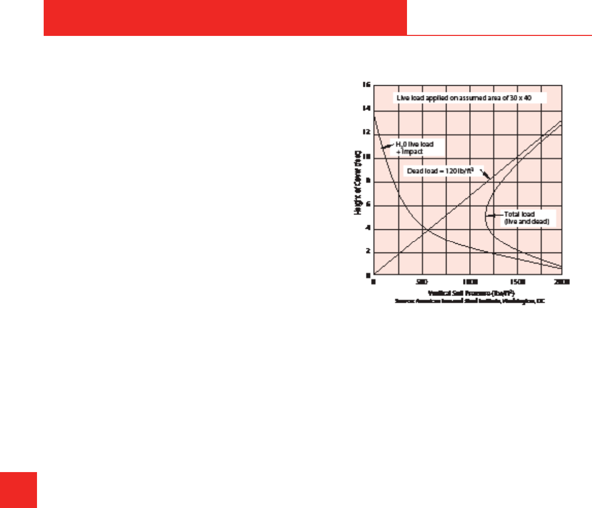
655 Andover Street, Lawrence, MA 02148 • Tel: 800-343-3618, 781-321-5409
Fax: 800-787-6861 • https://www.asahi-america.com • Email: [email protected]
Max allowable soil load _____________ per linear foot.
If the actual load is less than the allowable load, the
installation is acceptable, providing that a 2:1 safety
factor is present.
6DIHW\)DFWRU 0D[DOORZDEOHORDGDFWXDOVRLOORDG
SF = ________________________________________
If the maximum allowable load is less than the actual
load, changes will have to be made, such as burial
depth, trench details, or pipe wall thickness. The
DOORZDEOHORDGVIRU'XR3UR
®
pipe are based on an
DOORZDEOHULQJGHÀHFWLRQRI¿YHSHUFHQWIRU33DQG
+'3(DQGWKUHHSHUFHQWIRU39')
Live Load Designs
For applications where live loads are present, a general
UXOHRIWKXPELVWRSODFHWKHSLSH¿YHIHHWEHORZWKH
source of the live load. If piping is only being exposed
to a live load for a short length of time and cannot be
SODFHG¿YHIHHWGRZQLWPD\EHDGYDQWDJHRXVWRVOHHYH
the pipe through a steel pipe or enclose it in concrete.
In general, live loads should be added to static earth
loads to determine the total load exerted on the pipe
under site conditions. In Figure G-3, H
2
O highway
ORDGLQJWKHHႇHFWVRIOLYHORDGDQGVWDWLFHDUWKORDGV
combined on a pipe can be viewed. In shallow depths,
VKDOORZHUWKDQWKH¿YHIRRWPDUNWKHHႇHFWRIWUDႈFLV
VLJQL¿FDQWDQGQHHGVWREHDGGHGWRWKHVWDWLFORDGWR
GHWHUPLQHWKHHႇHFW)URPWKHJUDSKLWLVGHPRQVWUDWHG
WKDWWKHHႇHFWRIDOLYHORDGEHFRPHVPLQLPDODWJUHDWHU
depths. In all cases of static and live loads, consult
$VDKL$PHULFD¶V(QJLQHHULQJ'HSDUWPHQWIRUDVVLVWDQFH
on design.
G
DOUBLE CONTAINED
G-6
Figure G-3. H
2
O highway loading
DOUBLE CONTAINED
Double Wall Chemical Pipe
System Design
'RXEOHFRQWDLQPHQWSLSLQJV\VWHPVDUHRQHRIWKH
most economical and reliable methods for protecting
against primary piping leaks of corrosive or hazardous
ÀXLGV7KH'XR3UR
®
and Fluid-Lok
®
V\VWHPVRႇHUHGE\
$VDKL$PHULFDDUHWKHRULJLQDODQGÀDJVKLSSURGXFWV
of the industry. When designed and applied correctly,
the system can be expected to have a long service life
WKDWRIWHQH[FHHGV\HDUV'RXEOHFRQWDLQHGV\VWHPV
FRQVWUXFWHGIURPWKHUPRSODVWLFPDWHULDOVRႇHUVLJQL¿FDQW
cost savings and superior chemical resistance over
their metal counterparts. A combination of government
regulations, increased concern over environmental
and personal safety, and a growing fear of litigation
has hastened the development and improvement
of double contained piping components into highly
engineered systems. With over 25 years of experience
in thermoplastic double containment piping, no other
FRPSDQ\FDQPDWFK$VDKL$PHULFD¶VH[SHULHQFHDQG
quality.
Use this guide to assist in the design and layout of a
double wall pipe system for multiple applications. This
guide highlights the areas that an engineer should take
into consideration when designing a system.
DESIGN & PRESSURE TESTING
ASAHI/AMERICA
Rev. 2013-A

655 Andover Street, Lawrence, MA 02148 • Tel: 800-343-3618, 781-321-5409
Fax: 800-787-6861 • https://www.asahi-america.com • Email: [email protected]
Cost, reliability, and ease of installation can all be
improved by careful planning in the conceptual and
design phases of any piping project. For double
containment systems, the following items must be given
careful consideration:
• When to use double containment piping
• Materials of construction
• System selection
• System sizing
• 6SHFLDOW\¿WWLQJV
• 'RXEOHFRQWDLQHGYDOYHV
• 7KHUPDOH[SDQVLRQSDUWLFXODUO\LPSRUWDQWLQ
thermoplastic systems)
• Hanging
• Burial
• Welding methods
• UV exposure and weatherability
Leak detection is also an important part of double
containment systems. Leak detection of some sort
is required on all underground double containment
systems. The type of leak detection, the installation
PHWKRGDQGWKHV\VWHPVHWXSDUHYHU\GLႇHUHQWIURP
system to system. For this reason, leak detection will be
discussed separately later in this section.
When to Use Double Containment Piping
Underground EPA Requirements
7KH86(QYLURQPHQWDO3URWHFWLRQ$JHQF\(3$KDV
adopted regulations on underground storage tanks
867VDQGUHODWHGSLSLQJ7KH(3$VWDWHVWKDWWKHVH
systems pose threats to the environment.
(3$UHJXODWLRQ&)5VSHOOVRXWWKHPLQLPXP
requirements for USTs that contain petroleum or
hazardous chemicals.
$VXPPDU\RIWKH(3$¶VUHTXLUHPHQWVWKDWDႇHFWGRXEOH
containment piping follows.
This is a brief overview. A project engineer needs a
thorough understanding of the regulations prior to
designing a system.
EPA’s Regulations Cover:
Media:$OOFKHPLFDOVOLVWHGXQGHU6XEWLWOHRI&)5
G
DOUBLE CONTAINED
G-7
Systems: All USTs and related piping.
System requirements: All USTs and pipes must be
installed so that a release from the product pipe is
contained or diverted to a proper collection system.
Containment may be done via a trench, dike, or double
containment pipe and tanks. The containment materials
must be able to hold the leaking product for a minimum
of 30 days. By then, scheduled inspections and periodic
monitoring should identify the failure and correct the
situation.
Leak detection:'UDLQDJHDQGVXFWLRQOLQHVUHTXLUH
monthly manual inspections for product line leaks.
3UHVVXUL]HGV\VWHPVUHTXLUHDXWRPDWLFPRQLWRULQJ
for product failure. In case of a leak, the system must
DXWRPDWLFDOO\UHVWULFWÀRZRIWKHSURGXFW
Compliance dates:7KH(3$KDVVHWUHTXLUHPHQWV
for the date of compliance for both new and existing
V\VWHPV&RQWDFW$VDKL$PHULFDIRUWKHODWHVWVWDQGDUG
RUYLVLWWKH(3$¶VZHEVLWHDWZZZHSDRUJ
Above ground:,QDGGLWLRQWRWKH(3$UHTXLUHPHQWVIRU
below grade systems, many companies have adopted
policies for overhead piping to protect personnel from a
possible leak of a harmful chemical.
Materials of Construction
The majority of double containment systems installed
worldwide are thermoplastic due to the ease of joining
and chemical resistance to hazardous media and
XQGHUJURXQGPRLVWXUH$VDKL$PHULFDRႇHUVVHYHUDO
materials to handle a wide range of applications.
Materials include:
• 3RO\SURS\OHQH
• 39')
• E-CTFE: Halar
®
• +'3(+LJK'HQVLW\3RO\HWK\OHQH
7KHFDUULHUSLSHWKHLQQHUSLSHDOVRNQRZQDVWKH
product pipe) material is selected based on common
piping practices using variables such as:
• :KDWFKHPLFDOVZLOOEHLQFRQWDFWZLWKWKHV\VWHP"
• :KDWDUHWKHFKHPLFDOFRQFHQWUDWLRQV"
• $WZKDWWHPSHUDWXUHZLOOWKHV\VWHPRSHUDWH"
• $WZKDWSUHVVXUHZLOOWKHV\VWHPRSHUDWH"
• :KDWLVWKHÀRZRIWKHPHGLDLQWKHV\VWHP"
By answering these questions, the proper materials
of construction for the carrier can be selected for the
project. To assist in the material selection, refer to the
FKHPLFDOUHVLVWDQFHWDEOHVLQ6HFWLRQ'$WKHUPRSODVWLF
DESIGN & PRESSURE TESTING
ASAHI/AMERICA
Rev. 2013-A

655 Andover Street, Lawrence, MA 02148 • Tel: 800-343-3618, 781-321-5409
Fax: 800-787-6861 • https://www.asahi-america.com • Email: [email protected]
system’s ratings for temperature and pressure are based
on water. The addition of certain chemicals will add
stress to the system and may reduce the recommended
operating parameters. For less aggressive chemicals,
the use of printed resistance tables is perfectly
suitable. For more aggressive chemicals or mixtures of
chemicals, the manufacturer of the pipe system should
be consulted.
After verifying the standard operating conditions, it
is necessary to examine other operations that might
DႇHFWWKHSLSLQJ7KHIROORZLQJLVDVDPSOHRILWHPVWR
investigate prior to specifying a material.
• :LOOWKHUHEHVSLNHVLQWHPSHUDWXUHRUSUHVVXUH"
• Is there a cleaning operation that the piping will be
H[SRVHGWR"
• ,I\HVZKDWLVWKHFOHDQLQJDJHQW"$WZKDW
WHPSHUDWXUHZLOOWKHFOHDQLQJEHFRQGXFWHG"
• Will the system be exposed to sunlight or other
VRXUFHVRI89"
Each of the previous questions should be answered,
and the desired material should be checked for
suitability based on the above factors, as well as any
others that might be special to the system in question.
Finally, in addition to verifying the temperature, pressure,
and media within the thermoplastic pipe material, it
is also necessary to verify other components in the
system, such as valves, gaskets, valve seat and seals,
etc. These should be examined in the same manner as
the pipe material.
Once the product pipe has been selected, the
containment pipe must be selected. In most cases,
the containment pipe is the same as the carrier pipe,
VXFKDVLQSRO\SURS\OHQHDQG+'3(V\VWHPV8VLQJ
the same material internally and externally yields
many time-saving advantages on a project. However,
in many systems where the product pipe required is a
PRUHH[SHQVLYHPDWHULDOVXFKDV39')RU(&7)(D
polypropylene outer shell is often used.
Sizing the containment pipe requires the consideration
RIPDQ\IDFWRUVWKDWDUHGLႇHUHQWWKDQWKRVHXVHGWRVL]H
the carrier.
These include:
• Static and live burial loading
G
DOUBLE CONTAINED
G-8
• Leak detection requirements
• Hanging requirements for above-ground applications
• 3K\VLFDOVSDFHFRQVWUDLQWV
• Manufacturability and availability
• Operating pressure
When a double contained system is buried, the
containment pipe bears the static soil load and the
G\QDPLFORDGLQJLPSRVHGE\WUDႈFHTXLSPHQWHWF
Section C provides a detailed discussion for calculating
static and dynamic loading to determine the required
wall thickness.
Leak detection requirements must also be considered.
'HSHQGLQJRQWKHW\SHRIOHDNGHWHFWLRQFKRVHQWKHUH
may be minimum requirements for the amount of
annular space necessary for successful installation and
operation. As a general rule of thumb, a minimum of
´RIDQQXODUVSDFHLVUHTXLUHGIRUWKHLQVWDOODWLRQRI
a continuous cable system. Leak detection options are
discussed in detail later in this section.
Hanging requirements and physical space constraints
are also important considerations. Often, trenches or
pipe racks are crowded with other systems, so the
containment must not be too large. The designer of a
system should specify the exact hanger location instead
of leaving this portion up to the installer.
0DQXIDFWXUDELOLW\DQGDYDLODELOLW\FDQDOVRLQÀXHQFH
the selection of containment pipe. There must
be adequate clearance between the carrier and
FRQWDLQPHQWWRIDFLOLWDWHHႈFLHQWPDQXIDFWXULQJ7KLV
LVHVSHFLDOO\LPSRUWDQWIRUWKHPDQXIDFWXULQJRI¿WWLQJV
$VDKL$PHULFDKDVVSHQWVHYHUDO\HDUVLPSURYLQJ
IDEULFDWLRQWHFKQLTXHVWRRႇHUWKHZLGHVWYDULHW\RIVL]HV
in the marketplace. The designer should also be careful
to design with standard pipe sizes to avoid costly delays
due to lack of availability.
2SHUDWLQJSUHVVXUHSDUDPHWHUVPD\EHTXLWHGLႇHUHQW
for the containment pipe than for the carrier. Often,
systems are designed so that any leaks into the annular
space drain directly into a manhole or sump. In these
open-ended systems, it is virtually impossible to build
XSVLJQL¿FDQWSUHVVXUH$VDPDWWHURIHFRQRP\WKH
containment pipe often has a lower pressure rating and
therefore a higher dimensional ratio than the carrier
pipe.
7KH¿QDOFRQVLGHUDWLRQZKHQFKRRVLQJWKHFRQWDLQPHQW
DESIGN & PRESSURE TESTING
ASAHI/AMERICA
Rev. 2013-A

655 Andover Street, Lawrence, MA 02148 • Tel: 800-343-3618, 781-321-5409
Fax: 800-787-6861 • https://www.asahi-america.com • Email: [email protected]
pipe is the environment in which it will be installed. Outer
UV exposure is not ideal for polypropylene systems, and
protection of the pipe may be required. If surrounding
temperatures are extremely low, then certain materials
ZLOOEHFRPHEULWWOHLQWKHFROG&RQVXOW$VDKL$PHULFDIRU
VSHFL¿FUHFRPPHQGDWLRQVLQWKHVHFDVHV
System Selection
As stated in the previous section, the material must
be selected based on the media to run through the
system, as well as the operating conditions such as
pressure, temperature, and media concentration. In a
double containment system, the selection of pipe and
associate pipe pressure ratings can be complex, as any
combination of material can be used.
$VDKL$PHULFDRႇHUVWKUHHV\VWHPVIRUGRXEOH
containment piping:
• 'XR3UR
®
• 3RO\)OR
®
• Fluid-Lok
®
Each system has its ideal purposes and advantages. A
description of the three systems follows.
Duo-Pro
®
7KH'XR3UR
®
V\VWHPLVWKHÀDJVKLSRIWKH$VDKL
$PHULFDGRXEOHFRQWDLQPHQWSLSLQJV\VWHPRႇHULQJV
'XR3UR
®
LVDYDLODEOHLQSRO\SURS\OHQH39')(&7)(
DQGLQDQ\FRPELQDWLRQRIWKHWKUHH'XR3UR
®
is
DYDLODEOHLQV\VWHPVUDQJLQJIURP´[´WR´[´,Q
addition, larger systems have been made available on
request.
'XR3UR
®
is a fabricated system made from extruded
SLSHDQGSULPDULO\PROGHG¿WWLQJV,WKDVDFRPSOHWH
UDQJHRIPROGHGSUHVVXUH¿WWLQJVWKDWDUHIDEULFDWHGLQWR
GRXEOHFRQWDLQPHQW¿WWLQJVDWWKHIDFWRU\,QDGGLWLRQ
'XR3UR
®
is ideal for drainage applications, having a
ZKROHFRPSOLPHQWRI¿WWLQJVIRUGUDLQDJHDSSOLFDWLRQV
It can be assembled using simultaneous butt fusion or
staggered butt fusion.
7KH'XR3UR
®
system is assembled using a support
GLVFRQHDFKHQGRIDSLSHRU¿WWLQJ7KHVXSSRUWGLVF
centers the carrier inside the containment and locks
the two pipes together for simultaneous fusion. On pipe
UXQVWKHVSLGHUFOLS¿WWLQJLVXVHGWRVXSSRUWWKHSLSH
inside the containment piping. Spider clips are spaced
based on hanging criteria by size and material and are
designed to avoid the point loading of the pipes.
G
DOUBLE CONTAINED
G-9
)LJXUH*6XSSRUWGLVFVDQGVSLGHUFOLS¿WWLQJV
3HUWKH(3$¶VUHTXLUHPHQWVDQ\GRXEOHFRQWDLQHG
system needs to have leak detection. The methods
of leak detection include manual inspection, low point
sensors, and continuous leak detection cable. The leak
detection cable is installed in between the annular space
EHWZHHQWKHLQQHUDQGRXWHUSLSH'XR3UR
®
is designed
WRSURYLGHVXႈFLHQWVSDFHIRUWKHLQVWDOODWLRQRIDOHDN
GHWHFWLRQFDEOH&RQWDFW$VDKL$PHULFDWHFKQLFDOVWDႇ
for an exact recommendation.
Figure G-5. Duo-Pro
®
piping system
Poly-Flo
®
7KH3RO\)OR
®
system is a unique dual extruded and
molded system. In all other double containment pipe
systems, the inner and outer components are made
separately and then assembled into a double wall
FRQ¿JXUDWLRQ7KLVDGGVWLPHDQGODERUWRHDFKSURMHFW
7KH3RO\)OR
®
system produces both the inner and
RXWHUSLSLQJDWWKHVDPHWLPH$VDKL$PHULFD¶VSDWHQWHG
extrusion process locks the pipe together by use of
FRQWLQXRXVVXSSRUWULEV,QDGGLWLRQPRVW¿WWLQJVLQWKH
system are molded as single-piece components. The
RQO\GHYLDWLRQLV+'3(PDWHULDOZKHUHPDQ\¿WWLQJVDUH
fabricated from double wall pipe.
3RO\)OR
®
LVDYDLODEOHLQ´[´´[´DQG´[´
DESIGN & PRESSURE TESTING
ASAHI/AMERICA
Rev. 2013-A

655 Andover Street, Lawrence, MA 02148 • Tel: 800-343-3618, 781-321-5409
Fax: 800-787-6861 • https://www.asahi-america.com • Email: [email protected]
&RQVXOW$VDKL$PHULFDIRUWKHDYDLODELOLW\RI´[
´3RO\)OR
®
is available in three materials: black
SRO\SURS\OHQH89VWDELOL]HG39')DQG+'3(,WLV
DXQLTXHV\VWHPZKHUHWKHFDUULHUSLSHKDVDQ2'
FRQVLVWHQWZLWK,36SLSHZKLOHWKHRXWHUSLSHLVDMDFNHW
QRWFRUUHVSRQGLQJWRDQ,36GLPHQVLRQ
3RO\)OR
®
is assembled using simultaneous butt fusion
only. The system is available with manual and low- point
leak detection sensors only. The use of a leak detection
cable is not possible due to the limited annular space.
Figure G-6. Poly-Flo
®
piping system
Fluid-Lok
®
The Fluid-Lok
®
V\VWHPLVDQDOO+'3(V\VWHP,WLV
PDQXIDFWXUHGLQDVLPLODUSURFHVVWRWKH'XR3UR
®
system. Fluid-Lok
®
is available in many sizes, ranging
IURP´[´WRV\VWHPVDVODUJHDV´[´
%HVLGHVEHLQJDQDOO+'3(V\VWHP)OXLG/RN
®
is
GLႇHUHQWWKDQ'XR3UR
®
LQWKDWPRVW¿WWLQJVDUH
IDEULFDWHGDQGQRWPROGHG)DEULFDWHG¿WWLQJVDUHLGHDO
IRUWKHDSSOLFDWLRQRIORQJVZHHSVDQGVZKLFKDUH
often required in these systems. Fluid-Lok
®
is designed
to accommodate leak detection low-point sensors or
FDEOH,QDGGLWLRQ+'3(PDQKROHVDUHDYDLODEOHDQG
can be directly welded to the pipe system to avoid
XQQHFHVVDU\¿WWLQJVDQGSURYLGHPRUHFRQVLVWHQF\DQG
leak protection.
G
DOUBLE CONTAINED
G-10
Figure G-7. Fluid-Lok
®
piping system
The availability of many materials and three piping
systems creates many choices. Each system is
GHVLJQHGIRUVSHFL¿FDSSOLFDWLRQVDQGDVVHPEO\
techniques. To assist in the proper selection of the
system, consider the following questions and answers.
Question/Answer
Q: $UH\RXRSHUDWLQJXQGHUSUHVVXUHRUGUDLQDJH"
A: 3UHVVXUHV\VWHPVPD\QHHGWRKDYHFRQVLVWHQW
SUHVVXUHUDWLQJ¿WWLQJVRQERWKWKHFDUULHUDQG
FRQWDLQPHQWSLSH':9¿WWLQJVDUHQRWDOORZHGLQ
pressure systems.
Q: 'R\RXUHTXLUHFRQVLVWHQWSUHVVXUHUDWLQJVRQWKH
FDUULHUDQGFRQWDLQPHQW"
A: If not, cost can be saved by using 150psi carrier
SLSLQJDQGSVLFRQWDLQPHQWSLSLQJ
Q: :KDWPDWHULDODUH\RXXVLQJ"
A: Material requirements may determine the system
you can choose.
Q: 'R\RXUHTXLUHFRQWLQXRXVFDEOHOHDNGHWHFWLRQ"
A: 2QO\WKH'XR3UR
®
and Fluid-Lok
®
systems can
accommodate cable systems.
DESIGN & PRESSURE TESTING
ASAHI/AMERICA
Rev. 2013-A

655 Andover Street, Lawrence, MA 02148 • Tel: 800-343-3618, 781-321-5409
Fax: 800-787-6861 • https://www.asahi-america.com • Email: [email protected]
Figure G-9. Locking inner and outer pipes
'RJERQHVDUHDYDLODEOHLQVROLGDQGDQQXODUIRUPV
$VROLG'RJERQHGRHVQRWDOORZWKHSDVVDJHRIÀXLG
in the annular space to pass through, while annular
'RJERQHVZLOODOORZWKHSDVVDJH7KHSODFHPHQWDQG
SXUSRVHRIWKH¿WWLQJZLOOGHWHUPLQHWKHVW\OHUHTXLUHG
'RJERQH¿WWLQJVDUHDYDLODEOHLQWKH'XR3UR
®
and
Fluid-Lok
®
V\VWHPV7KH3RO\)OR
®
system does not
UHTXLUHWKH¿WWLQJDVWKHSLSHLVFRQWLQXRXVO\VXSSRUWHG
and locked together.
)LQDOO\WKH'RJERQHFDQEHXVHGIRUFRQQHFWLQJ
low-point leak detectors, ventilation, and drainage.
When designing a double wall system, it is important
to incorporate high point vents to eliminate air from the
system. In addition, in the event of a leak, a drainage
method for the containment pipe is required. Connection
methods for these valve requirements are shown in
Figures G-10 through G-13.
Figure G-10. Ventilation of inner pipe: Duo-Pro
®
and
Fluid-Lok
®
System Sizing
,WLVUHFRPPHQGHGWRPDLQWDLQÀRZUDWHVEHORZD
YHORFLW\RIIWVHFRQGZKHQXVLQJDQ\WKHUPRSODVWLFZLWK
a hazardous chemical. High velocities can lead to water
hammer in the event of an air pocket in the system.
Water hammers can generate excessive pressures
that can damage a system. For safety reasons, high
velocities should be avoided.
In addition, high velocities also mean added pressure
drop, which, in turn, increases demand on the pump.
,IWKHÀRZYHORFLW\LVQRWUHTXLUHGLWLVUHFRPPHQGHG
to size a system with minimal pressure drop. It is also
recommended to oversize a design to allow for future
expansion or chemical demand. Once a system is in
SODFHLWLVGLႈFXOWWRDGGFDSDFLW\WRLW
Specialty Fittings
'RXEOHFRQWDLQPHQWV\VWHPVIRUWKHPRVWSDUWFDQ
be thought of in the same manner as single wall piping
systems with a few exceptions. In a double wall system,
the issue of thermal expansion is more complicated,
welding is similar but not the same, and the outer
containment pipe must have a start and stop.
7KHPDMRU¿WWLQJWKDWVHWV$VDKL$PHULFDV\VWHPVDSDUW
from all other double wall systems is the patented
'RJERQHIRUFHWUDQVIHU¿WWLQJ7KH'RJERQH¿WWLQJ
can be used in many ways to assist in the design of a
proper double containment piping system.
7KH'RJERQHLVXVHGIRU
• Locking the inner and outer pipes together
• Compartmentalizing pipe section
• Termination of the containment pipe
• Sensor installation
• Control of thermal expansion
)LJXUHV*WKURXJK*GHSLFWDIHZXVHVRIWKH
'RJERQH
Figure G-8. Outer containment termination
G
DOUBLE CONTAINED
G-11
DESIGN & PRESSURE TESTING
ASAHI/AMERICA
Rev. 2013-A

655 Andover Street, Lawrence, MA 02148 • Tel: 800-343-3618, 781-321-5409
Fax: 800-787-6861 • https://www.asahi-america.com • Email: [email protected]
Figure G-11. Drainage of containment pipe: Duo-Pro
®
and Fluid-Lok
®
Figure G-12. Ventilation of inner pipe: Poly-Flo
®
system
Figure G-13. Drainage of containment pipe:
Poly-Flo
®
system with low point sensor
G
DOUBLE CONTAINED
G-12
Double Contained Valves
In pressurized systems, the necessity of valves can be
accomplished without interrupting the integrity of the
GRXEOHFRQWDLQPHQWV\VWHP'RXEOHFRQWDLQHGYDOYHV
are available in many shapes and forms; they are also
DYDLODEOHLQDQ\VW\OHYDOYHVXFKDVEDOOEXWWHUÀ\
diaphragm, check, and gate. The valve selected, based
on the application, determines the shape of the outer
containment.
7KHIROORZLQJ¿JXUHVGHPRQVWUDWHDIHZYDOYH
FRQ¿JXUDWLRQVWKDWDUHDYDLODEOHIURP$VDKL$PHULFD
Other options are readily available on request.
Figure G-14. Double contained ball valve with stem
extension: Duo-Pro
®
system
Figure G-15. Double contained ball valve without
stem extension: Poly-Flo
®
system
DESIGN & PRESSURE TESTING
ASAHI/AMERICA
Rev. 2013-A

655 Andover Street, Lawrence, MA 02148 • Tel: 800-343-3618, 781-321-5409
Fax: 800-787-6861 • https://www.asahi-america.com • Email: [email protected]
Figure G-16. Double contained diaphragm valve with
stem extension: Poly-Flo
®
system
0RUHWKDQYDOYHVFDQEHLQVWDOOHG,WHPVVXFKDVÀRZ
meters and temperature and pressure monitors can also
be incorporated into the internal containment portion
RIWKHV\VWHP&RQWDFW$VDKL$PHULFD¶V(QJLQHHULQJ
'HSDUWPHQWWRGLVFXVV\RXUSDUWLFXODUQHHGV,WLV
important to specify and design in the need to access
valves for maintenance purposes.
Thermal Expansion
Based on your operating criteria, thermal expansion
may need to be considered. For systems maintained
at consistent temperatures, compensation for thermal
HႇHFWVPD\QRWEHUHTXLUHG,QDGRXEOHFRQWDLQHG
piping system, three types of expansion can occur:
• The carrier pipe is exposed to thermal changes,
while the containment remains constant. This is
typically possible when the carrier pipe is exposed
to liquids of various temperatures, while the outer
containment is in a constant environment, such as in
buried applications.
• The containment piping experiences thermal
changes, while the carrier remains constant. The
typical application is outdoor pipe racking with
constant temperature media being transported in the
carrier.
• Both inner and outer pipes experience temperature
changes.
7KH'RJERQH¿WWLQJLVDSURYHQDQGHႇHFWLYHZD\WR
control thermal expansion where a restrained system is
acceptable. It can also be used to direct the growth of
DÀH[LEOHV\VWHP)RUV\VWHPVPDLQWDLQHGDWFRQVLVWHQW
WHPSHUDWXUHVFRPSHQVDWLRQIRUWKHUPDOHႇHFWVPD\
not be required. However, it is important to review all
aspects of the operating environment, such as:
G
DOUBLE CONTAINED
G-13
• Is it outdoors where it will be exposed to changing
ZHDWKHU"
• Is the system spiked with a high temperature
FOHDQLQJVROXWLRQ"
• :LOOWKHV\VWHPUXQDWDVLJQL¿FDQWO\KLJKHURUORZHU
WHPSHUDWXUHWKDQWKHLQVWDOODWLRQWHPSHUDWXUH"
The occurrence of any thermal change in a plastic
system will cause the material to expand or contract.
Thermoplastic systems can be used in hot applications
and applications where the temperature is cyclical; it just
UHTXLUHVDQDO\VLVRIWKHWKHUPDOH[SDQVLRQHႇHFWV,Q
PRVWFDVHVWKHXVHRIH[SDQVLRQVRႇVHWVDQGSURSHU
hanging techniques is all that is required to ensure a
proper design.
Hot systems also reduce the rigidity of thermoplastic
piping, which, in turn, decreases the support spacing
between hangers. In smaller dimensions, it is
recommended to use continuous supports made of
some type of channel or split plastic pipe.
Finally, the use of hangers as guides and anchors
becomes important. Certain hangers should be used
as guides to allow the pipe to move in-line, while other
hangers should be anchoring locations used to direct the
expansion into the compensating device. The anchors
and hangers should be designed to withstand the
thermal end-load.
,QDEXULHGV\VWHPWKHVWDQGDUG'RJERQH¿WWLQJZLOO
lock the inner and outer pipes together. The surrounding
JURXQGDQG¿OOVKRXOGHOLPLQDWHWKHPRYHPHQWRIWKH
outer pipe. In systems that are hung, the outer pipe
hanger must withstand the thermal end-load. To properly
KDQJWKHVHV\VWHPVDVSHFLDO5HVWUDLQW'RJERQHLV
recommended at the hanger locations.
Figure G-17. Dogbones
DESIGN & PRESSURE TESTING
ASAHI/AMERICA
Rev. 2013-A

655 Andover Street, Lawrence, MA 02148 • Tel: 800-343-3618, 781-321-5409
Fax: 800-787-6861 • https://www.asahi-america.com • Email: [email protected]
Hanging
As in any thermoplastic system, the selection of hangers
is an important decision. Hangers that scratch or create
point loads on the pipe are not recommended. The ideal
hanger is a thermoplastic component. In many cases, an
all-plastic hanger may not be available. In these cases,
a metal hanger is acceptable, but precautions should
be taken. Any sharp edges on the hanger should be
removed. A cushion made of rubber is recommended
in the event that the pipe shifts because it will prevent
scratching.
Burial
'XHWR(3$UHTXLUHPHQWVWKHEXULDORIGRXEOH
containment piping is a common practice. In most cases,
the burial of a double wall pipe is the same as that of a
single wall pipe system. Careful consideration of the soil
W\SHFRPSDFWLRQWUHQFKGHWDLOLQJEDFN¿OOORDGHWFLV
necessary when considering the proper design.
Live loads also pose the added complication when
burying a system. It is important to look at the possibility
of the pipe system being driven over, as well as the type
of vehicle that would be creating the live load.
In the design, it is imperative to call out the
recommendations of the burial in the details of the
drawing set. By calling these details out, the contractor
will be in a better position to properly install the pipe as
required.
Welding Methods
$OOGRXEOHFRQWDLQPHQWV\VWHPVRႇHUHGE\$VDKL
America are available for butt fusion assembly. Butt
fusion provides reliable fusion, but it is also ideally suited
for the double wall system. By properly aligning the
carrier and containment piping with the support disc,
both the inner and outer pipe can be welded at the same
time. This reduces the assembly time, as well as the
QHHGIRUH[WUD¿WWLQJVVXFKDVFRXSOLQJV:KDWFDQEH
accomplished in one weld can take up to four welds in
RWKHUV\VWHPVZHOGWKHLQQHUDQGRXWHUVHSDUDWHO\RQ
either side of a coupling).
When building a system that is made of dissimilar
PDWHULDOVH[DPSOH39')[3URWKHSLSHV
FDQQRWEHZHOGHGVLPXOWDQHRXVO\GXHWRGLႇHUHQWKHDW
and joining force requirements. For these systems,
staggered welding is required, where the inner pipe is
ZHOGHG¿UVWDQGWKHRXWHUSLSHZHOGHGVHFRQGXVLQJ
a special annular heating element. Staggered fusion
G
DOUBLE CONTAINED
G-14
does take more time due to the extra welds, but it still
proves to be economical when compared to using
VLPLODUPDWHULDOVVXFKDV39')RQERWKWKHFDUULHU
and containment pipe, depending on pipe size, project
requirements, and installation environment.
UV Exposure and Weatherability
All thermoplastic materials react to the exposure
RI89GLႇHUHQWO\39')DQG(&7)(PDWHULDOVDUH
completely UV resistant over the course of their design
life. However, certain chemicals containing Cl anions
exposed to UV light can create a free radical Cl that will
DWWDFNWKH39')SLSHZDOO
3RO\SURS\OHQHLVQRW89VWDEOH,QGLUHFWH[SRVXUHWR
VXQOLJKWLWZLOOEUHDNGRZQ7KHHႇHFWFDQEHVHHQLQ
a noticeable color change in the pipe. In pigmented
33V\VWHPVWKHFRORUFKDQJHZLOODFWXDOO\FUHDWHD
protective shield on the outer layer of the pipe and
SUHYHQWIXUWKHUGHJUDGDWLRQ)RU33SLSHVZLWKDZDOO
WKLFNQHVVJUHDWHUWKDQ´WKHHႇHFWRI89LVQRUPDOO\
reduced and can be used outside. However, it is still
recommended to protect it from UV exposure for added
safety.
The Fluid-Lok
®
+'3(PDWHULDOLV89VWDELOL]HG
Fluid-Lok
®
pipes contain carbon black to make the
material UV stable and acceptable for use in outdoor
DSSOLFDWLRQV2WKHU+'3(PDWHULDOVPDGHE\RWKHU
manufacturers may require protection. Be sure to
consult manufacturer prior to selecting a pipe system.
Leak Detection Design
In all buried applications of double containment piping,
WKH(3$&)5KDVVHWDUHTXLUHPHQWIRUOHDN
GHWHFWLRQ'UDLQDJHDQGVXFWLRQOLQHVUHTXLUHPRQWKO\
PDQXDOLQVSHFWLRQVIRUSURGXFWOLQHOHDNV3UHVVXUL]HG
systems require automatic monitoring for product failure.
In case of a leak, the system must automatically restrict
WKHÀRZRIWKHSURGXFW
$VDKL$PHULFD¶VV\VWHPVDUHGHVLJQHGWRDFFRPPRGDWH
PDQ\GLႇHUHQWWHFKQRORJLHVIRUGHWHFWLQJDOHDN7KH
following methods are acceptable:
• Low-point leak detection sensors
• Continuous leak detection cable systems
9LVXDOLQVSHFWLRQRQO\DFFHSWDEOHRQGUDLQDJH
systems)
The selection of the leak detection system will play
DESIGN & PRESSURE TESTING
ASAHI/AMERICA
Rev. 2013-A

655 Andover Street, Lawrence, MA 02148 • Tel: 800-343-3618, 781-321-5409
Fax: 800-787-6861 • https://www.asahi-america.com • Email: [email protected]
a critical role in the layout of the piping system. For
instance, if a cable method is used, it will require
DGGLWLRQDO¿WWLQJVFDOOHGDFFHVVSRUWVIRUSXOOLQJWKH
FDEOH3LSHVDQG¿WWLQJVZLOOQHHGWREHRUGHUHGZLWK
pull ropes installed at the factory. Finally, the placement
of the cable will need to be factored in. For some
installations, only the main trunk line will have cable; in
others, the cable will split and run up each of the branch
lines.
This guide has been created to assist in the pipe layout
and design of a leak detection system. Each type of
V\VWHPLVGLVFXVVHGLQUHJDUGWRLWVXVHLQDQ$VDKL
America double containment piping system.
Low Point Leak Detection Sensors
Low point leak detection sensors can be used in any of
$VDKL$PHULFD¶VGRXEOHZDOOV\VWHPV
• 3RO\)OR
®
• 'XR3UR
®
• Fluid-Lok
®
)RUWKH3RO\)OR
®
system, low-point sensors are the
only automatic system available.
Low-point leak detection is relatively straightforward
in terms of design. The sensing technology consists
RIHLWKHUFDSDFLWLYHRUÀRDWW\SHVZLWFKHV7KHVH
switches are placed in strategic locations throughout
a system to properly identify leaks and then determine
their location within a reasonable length of pipe. If an
LQVXႈFLHQWDPRXQWRIVHQVRUVLVXVHGDQGDOHDNRFFXUV
determining the location of that leak can be extremely
GLႈFXOWHVSHFLDOO\LIWKHSLSLQJLVEXULHG,WLVDOZD\V
more practical to use a few more sensors at the time of
installation, as it could lead to huge cost savings in the
long run in the event of a system leak.
Mounting of the Sensor
$VDKL$PHULFDSLSHV\VWHPVFDQDFFRPPRGDWH
PRXQWLQJVHQVRUVLQDYDULHW\RIGLႇHUHQWPHWKRGV,Q
some cases, it is ideal to place the sensor with as tight
RIDSUR¿OHWRWKHSLSHDVSRVVLEOHLQRWKHULQVWDQFHV
a low-point leak sensor installation may also require a
valve for drainage. When using low-point sensors in
below-grade applications, it is important that special
considerations are taken in the excavation to ensure that
the sensors are not damaged during installation or back
¿OO
G
DOUBLE CONTAINED
G-15
)LJXUHV*WKURXJK*GHSLFWDIHZDVVHPEOLHVIRU
mounting low-point sensors into the annular space of a
double contained pipe system.
Figure G-18. Drain and low-point Poly-Flo
®
system
Figure G-19. Simple connection, Duo-Pro
®
Fluid-
Lok
®
systems
Figure G-20. Connection with drain valve, Duo-Pro
®
/
Fluid-Lok
®
systems
DESIGN & PRESSURE TESTING
ASAHI/AMERICA
Rev. 2013-A

655 Andover Street, Lawrence, MA 02148 • Tel: 800-343-3618, 781-321-5409
Fax: 800-787-6861 • https://www.asahi-america.com • Email: [email protected]
Figure G-21. End-of-line connection option, Duo-
Pro
®
/ Fluid-Lok
®
systems
Location of the Sensors
7KHORFDWLRQRIWKHVHQVRUVVKRXOGEHEDVHGRQ¿QGLQJ
the leak with relatively no confusion. By placing the
VHQVRUVRQWKHEUDQFKRIWHHVRUODWHUDOZ\HW\SH
FRQQHFWLRQVWKHOLQHFDXVLQJWKHOHDNLVHDVLO\LGHQWL¿HG
In addition, placing the sensor every 100 to 150 feet
reduces the area that would be in question if a leak was
to occur.
Figure G-22 shows an example of a system and the
ideal locations for the low-point sensors.
Figure G-22. Sample locations for low point sensors
G
DOUBLE CONTAINED
G-16
Compartmentalizing the System
The practice of compartmentalizing the outer
containment pipe is in conjunction with the strategic
placement of sensors. Should a major leak were to
occur, it is possible that more than one sensor could
be tripped in a short time frame. If you have no way of
NQRZLQJZKLFKVHQVRUWULSSHG¿UVWWKHQWKHYDOXHRI
multiple sensors is lost.
8VLQJWKH'RJERQH¿WWLQJVHFWLRQVRIWKHDQQXODU
space can be made into individual compartments. In the
FDVHRIDOHDNWKHÀXLGZLOOSDVVLQWRWKHDQQXODUVSDFH
but it will be locked into a compartment and not allowed
to spread throughout the system. This method has two
advantages: one helps to identify leak locations, and the
other reduces the need to dry out a large section of the
annular space once the leak is found and repaired.
)LJXUH*GHPRQVWUDWHVWKHXVHRIVROLG'RJERQHV
to create compartments.
Figure G-23. Leak detection compartments
Continuous Cable Leak Detection Systems
&RQWLQXRXVFDEOHOHDNGHWHFWLRQV\VWHPVRႇHUWKH
best method for locating a leak in the annular space
of a double containment pipe system. A cable system
can generally pinpoint the location of the leak with an
accuracy of ±0.5 feet. It can also incorporate low-point
SUREHVWRRႇHUPD[LPXPÀH[LELOLW\WRWKHGHVLJQHU
Entire systems can be mapped out, installed, and fed
back to an easy-to-understand operating panel. Most
large systems use leak detection cable as the preferred
method for monitoring the system.
All pressure double wall pipe systems are required
to have automated leak detection in below-grade
applications. In these cases, cable is the recommended
method.
The discussion of leak detection cable is broken down
into two topics: the pipe layout requirements and the
electrical cable layout requirements.
Pipe Layout Requirements (Annular Space)
Leak detection cable can be used in the following
$VDKL$PHULFDV\VWHPV
DESIGN & PRESSURE TESTING
ASAHI/AMERICA
Rev. 2013-A

655 Andover Street, Lawrence, MA 02148 • Tel: 800-343-3618, 781-321-5409
Fax: 800-787-6861 • https://www.asahi-america.com • Email: [email protected]
• 'XR3UR
®
• Fluid-Lok
®
Unfortunately, due to the narrow annular space in a
3RO\)OR
®
system, the cable cannot be pulled through the
system, eliminating its use. Continuous cable systems
UHTXLUHDPLQLPXPRI´RIDQQXODUVSDFHWRSXOOFDEOH
WKURXJKHDVLO\,Q'XR3UR
®
and Fluid-Lok
®
systems,
FHUWDLQSLSHFRQ¿JXUDWLRQVFDQKDYHVPDOODQQXODU
VSDFHPDNLQJWKHFDEOHSXOOGLႈFXOWRULPSRVVLEOH
)RULQVWDQFH[3UR['XR3UR
®
systems
KDYHDVSDFHDOODURXQG$IWHUDFFRXQWLQJIRU
WKHZHOGEHDGWKHVSDFHZLOOEHORZHUWKDQ´)RU
WKLVDSSOLFDWLRQ[3UR[RU[3UR
[VKRXOGEHFRQVLGHUHGWRHDVHWKHLQVWDOODWLRQ
&RQVXOW$VDKL$PHULFD¶V(QJLQHHULQJ'HSDUWPHQWIRU
WKHDYDLODEOHDQQXODUVSDFHRQ'XR3UR
®
systems and
Fluid-Lok
®
systems.
To clarify once again, for ease of installation, the annular
VSDFHQHHGVWREHDPLQLPXPRI´WRDFFRPPRGDWH
easy cable pulls.
Pipe
There are no special requirements for pipe. Both the
'XR3UR
®
and Fluid-Lok
®
systems are designed to
accommodate cable leak detection. Support discs on
WKHHQGVRISLSHDQG¿WWLQJVSURYLGHDZLGHRSHQLQJRQ
the bottom of the pipe, as well as either cut outs or vent
holes in other sections, depending on the pipe size.
On pipe runs, the carrier pipe is supported by the use
of spider clips, which support the carrier pipe without
blocking the bottom of the annular space.
Figure G-24. Two typical end-of-pipe support discs
to accommodate leak detection
There are only two important items to keep in mind.
When ordering pipe, ensure that pull rope is ordered
to be installed on the pipe. The second is during
LQVWDOODWLRQLWLVFULWLFDOWRDOLJQWKHSLSHDQG¿WWLQJV
properly to ensure that support disc openings are
located on the bottom. Forgetting this can lead to
VLJQL¿FDQWGLႈFXOW\ZKHQWU\LQJWRSXOOFDEOHLQWRWKH
G
DOUBLE CONTAINED
G-17
system.
Access Points
$VDKL$PHULFDRႇHUVDVWDQGDUG¿WWLQJIRUDFFHVVLQJWKH
DQQXODUVSDFHNQRZQDVWKH$FFHVV7HHRU3XOO3RUW
7HH:KLOHLWFDQEHFRPPRQSUDFWLFHLQ+'3(V\VWHPV
to cut windows into the pipe to access the rope or cable
and then weld a saddle on afterward, this is not an
acceptable design. While it is possible to cut windows,
this should only be used when the rope or cable is
caught in the line and no other alternative is available.
Access tees are supplied with a low-pressure thread-
on cap; for full pressure rating on the outer wall pipe, a
ÀDQJHDQGEOLQGÀDQJHFRQ¿JXUDWLRQLVDYDLODEOH
Figure G-25. Access tee with threaded cover
)LJXUH*$FFHVVWHHZLWKÀDQJHGFRYHU
Access tees are supplied in two pieces, allowing the
installer to weld the proper pipe height to the tee base to
come up to grade.
Once the selection of the access tee style is determined,
the strategic location of the pull ports is required. In
general, pull ports should be located at no more than
500-foot intervals on straight runs. Each 90° change in
direction is approximately equal to 150 feet of straight
UXQ3XOOSRUWVVKRXOGEHLQVWDOOHGWRDYRLGELQGLQJWKH
pull rope. Access tees should also be placed at the
beginning and the end of branch locations requiring
cables. For tie-ins to the main cable, it is best to place
the access tee on the main run in front of the branch
location.
Figure G-27 shows a small schematic on a drainage
DESIGN & PRESSURE TESTING
ASAHI/AMERICA
Rev. 2013-A
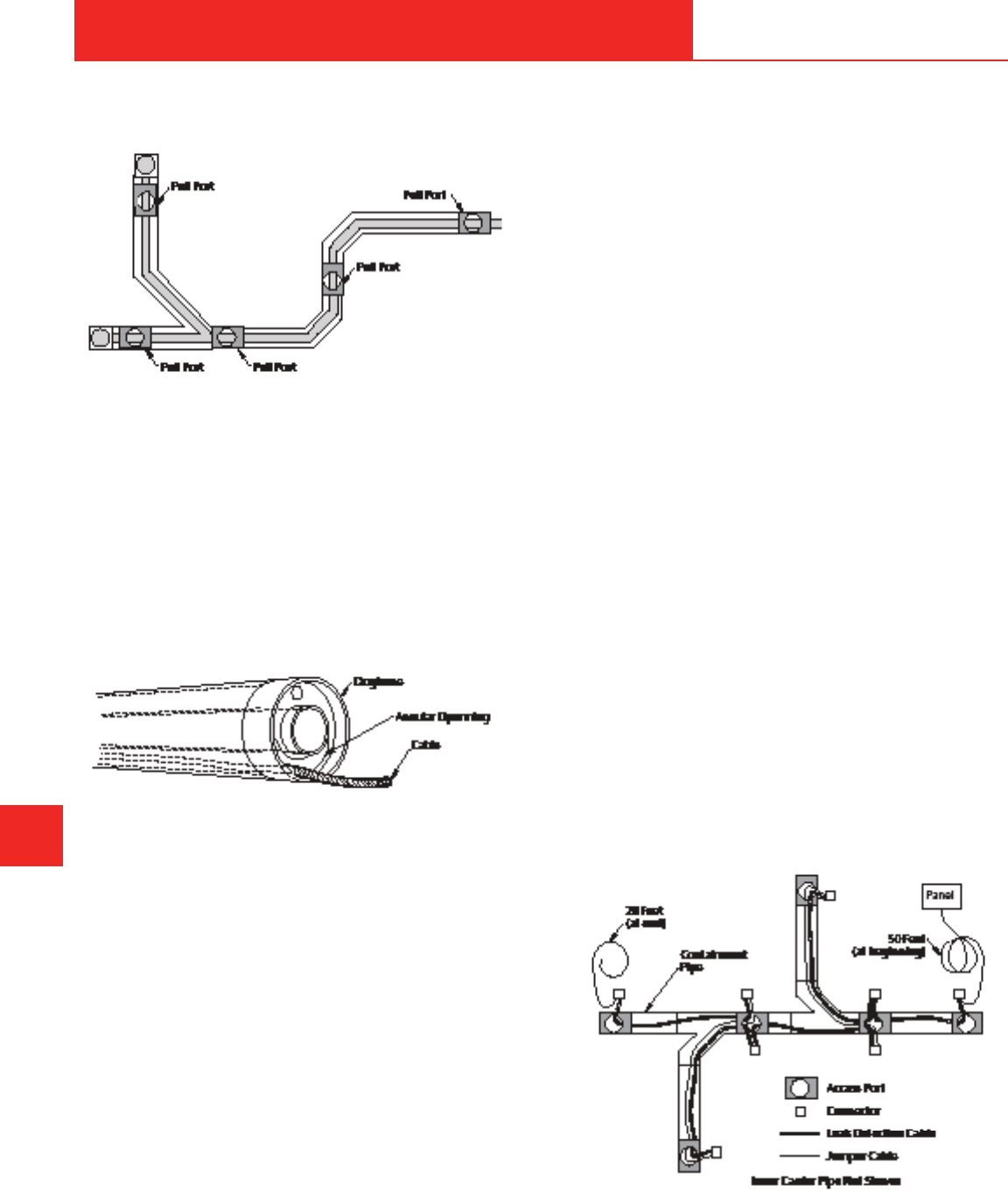
655 Andover Street, Lawrence, MA 02148 • Tel: 800-343-3618, 781-321-5409
Fax: 800-787-6861 • https://www.asahi-america.com • Email: [email protected]
system and the proper location of the access port.
Figure G-27. Pull port locations for leak detection
cable
Dogbones in a Cable System
,QDGRXEOHFRQWDLQPHQWV\VWHPWKH'RJERQH¿WWLQJLV
used to lock the inner pipe together for proper restraint
or for the control of thermal expansion. Unlike low-
point systems, creating compartments in the system is
QRWSUDFWLFDO,I'RJERQH¿WWLQJVDUHUHTXLUHGLQWKH
system, the use of the annular style is required to allow
cable to pass through.
Figure G-28. Annular Dogbone with cable
Sensor Cable Requirements
Sensor Cable
The proper selection of the sensor cable is imperative to
the successful operation of any leak detection system.
Most systems use a specially designed coaxial cable
for sensing leaks. Some cables are designed to sense
only water, others are designed to sense corrosive
chemicals, and some are designed to sense the
presence of hydrocarbons. There are also combinations
of these available that can sense corrosive water-based
liquids while ignoring hydrocarbons and vice versa;
in addition, there are some cables that can sense
water and hydrocarbons. These selections increase
WKHÀH[LELOLW\RIV\VWHPDSSOLFDWLRQV7KHFKHPLVWU\RI
the media must be considered to ensure the proper
selection of the sensing cable.
G
DOUBLE CONTAINED
G-18
Jumper Cable
Jumper cable is used to connect sensor cable segments
and probes together to form the sensing string. Jumper
FDEOHLVQRWDႇHFWHGE\FRQWDFWZLWKZDWHU+RZHYHU
installation in conduit is recommended to prevent
physical damage. If needed, jumper cable can be
directly buried.
The Connectors
The cable connection is perhaps the most critical
component to a hassle-free commissioning of the
system. Factory training of all personnel installing
connectors is strongly recommended to save many
hours troubleshooting a system with poor connections.
The connectors are typically standard UHF coaxial cable
connectors that are connected together with an adapter.
Because there is the possibility of the connection
getting wet in the event of a leak, each connection
must be carefully sealed with shrink tubing upon the
commissioning of the system.
The Control Panel
The control panel is the heart of the leak detection
system. It is typically mounted in a location that is
convenient for an operator to monitor its status. The
FRQWUROSDQHOFDQEHRUGHUHGLQVHYHUDOFRQ¿JXUDWLRQV
Some are multi-channel devices that are capable
of monitoring several systems simultaneously. Care
must also be taken to specify a panel that is capable
of monitoring the required length of sensor cable. The
control panel should have a visual readout of some
sort and a keypad for operation. It should also provide
provisions to interface with a computer to use diagnostic
and programming tools that are available.
Figure G-29. Layout of the cable with jumpers
DESIGN & PRESSURE TESTING
ASAHI/AMERICA
Rev. 2013-A

655 Andover Street, Lawrence, MA 02148 • Tel: 800-343-3618, 781-321-5409
Fax: 800-787-6861 • https://www.asahi-america.com • Email: [email protected]
Visual Inspection Monitoring
For drainage-only applications, an alternative method
to automated leak detection is manual inspection. As
long as monitoring can be accomplished every 30 days
and recorded, manual inspection is allowed. For manual
inspection, low-point drains are placed at collection
points in line as required. By designing in-wells, systems
can be opened and the annular space can be inspected
to sight a possible leak. Manual inspection can also
be accomplished at the end of the line. Figures G-30
DQG'VKRZWZRSRVVLEOHGHVLJQVIRUPDQXDOOHDN
GHWHFWLRQ3UREHVFDQDOVREHSODFHGLQZHOOVDVD
manner of automated detection with a view point.
Figure G-30. In-line inspection well
Figure G-31. End-of-line inspection wall
Burial Practices for Double Wall Piping
The procedure is the same as that of a single wall
system. All calculations should be based on the outer
ZDOOFRQWDLQPHQWSLSH2'DQGZDOOWKLFNQHVV
G
DOUBLE CONTAINED
G-19
If leak detection cable is used on a buried double wall
V\VWHPLWLVQHFHVVDU\WRFDOFXODWHWKHDFWXDOGHÀHFWLRQ
and the resulting annular space to ensure that the cable
will have adequate clearance. See Figure G-32.
)LJXUH*'HÀHFWLRQRIGRXEOHFRQWDLQHGSLSH
7KHIROORZLQJIRUPXODLVXVHGWRFDOFXODWHGHÀHFWLRQRQ
the containment pipe.
Installation of a Buried System
These preparations can be used for either single wall or
double contained piping systems.
Trench Preparation – General
The recommended trench width for both single and
double wall can be found by adding one foot to the width
of the pipe to be buried. Larger trench widths can be
tolerated, but trench widths greater than the diameter
plus two feet typically produce large loads on the pipe.
)RUVPDOOGLDPHWHUSLSHV´DQGOHVVVPDOOHUWUHQFK
widths are suggested. The important point to remember
is that the trench width at the top of the conduit is
the dimension that determines the load on the pipe.
Therefore, the sides of the trench can be sloped at an
angle starting above this point to assist with minimizing
VRLOORDGVLQORRVHVRLOFRQGLWLRQVSULRUWRFRPSDFWLRQ
DESIGN & PRESSURE TESTING
ASAHI/AMERICA
Rev. 2013-A

655 Andover Street, Lawrence, MA 02148 • Tel: 800-343-3618, 781-321-5409
Fax: 800-787-6861 • https://www.asahi-america.com • Email: [email protected]
If the trench widths described are exceeded, or if the
pipe is installed in a compacted embankment, it is
recommended that embedment should be compacted to
´SLSHGLDPHWHUIURPWKHSLSHRQERWKVLGHV,IWKLV
distance is less than the distance to the trench walls,
then the embedment materials should be compacted all
the way to the trench wall.
When installing long lengths of piping underground, it
may not be necessary to use elbows, as long as the
PLQLPXPUDGLLRIEHQGLQJIRUVSHFL¿FGLDPHWHUVDQGZDOO
thicknesses are observed. If the soil is well compacted,
thrust blocks are not required. However, if changes of
directions are provided with tees or elbows, or if the
soil is not well compacted, thrust blocks should be
provided. The size and type of a thrust block are related
to maximum system pressure, size of pipe, direction
RIFKDQJHYHUWLFDORUKRUL]RQWDOVRLOW\SHDQGW\SHRI
¿WWLQJRUEHQG7RGHWHUPLQHWKHWKUXVWEORFNDUHDLWLV
suggested that a geotechnical engineer be consulted
and soil bearing tests be conducted, if deemed
necessary.
If the bottom of the trench is below the water table,
actions must be taken to adequately correct the
situation. The use of well points or underdrains is
suggested in this instance, at least until the pipe has
EHHQLQVWDOOHGDQGEDFN¿OOLQJKDVSURFHHGHGWRWKH
SRLQWDWZKLFKÀRWDWLRQFDQQRORQJHURFFXU7KHZDWHU
in the trench should be pumped out, and the bottom of
the trench should be stabilized with the use of suitable
foundation material, compacted to the density of the
bedding material. In a double containment system,
annular spaces must be sealed to prevent water from
getting into the space.
For unstable trench bottoms, as in muddy or sandy
soils, excavate to a depth of four to six inches below the
WUHQFKERWWRPJUDGHEDFN¿OOZLWKDVXLWDEOHIRXQGDWLRQ
material, and compact to the density of the bedding
material. Be sure to remove all rocks, boulders, or
ledges within six inches in any direction from the pipe.
$WDQFKRUVYDOYHVÀDQJHVHWFLQGHSHQGHQWVXSSRUW
should be provided by the use of a reinforcing concrete
SDGSRXUHGXQGHUQHDWKWKHSLSHWKDWLVHTXLYDOHQWWR¿YH
WLPHVWKHOHQJWKRIWKHDQFKRUVYDOYHVRUÀDQJHV,Q
addition, reinforcing rods should be provided to securely
keep the appurtenance from shifting, thereby preventing
shearing and bending stresses on the piping. It is
strongly suggested that an elastomeric material be used
to prevent stress concentration loading on the piping
caused by the reinforcing rod.
G
DOUBLE CONTAINED
G-20
/D\LQJRI3LSH/LQHDQG%DFN¿OOLQJ3URFHGXUH
Caution must be exercised so that straight lengths
or piping prepared above ground does not exceed
the minimum bending radius of the piping. For a
JLYHQWUHQFKKHLJKW³K´WKHPLQLPXPOHQJWKRISLSLQJ
necessary to overcome failure due to bending strain can
be determined by the following procedure.
Step 1.
'HWHUPLQHWUHQFKKHLJKW ³K´7KLVWUHQFKKHLJKWZLOO
HTXDWHWRWKHRႇVHWYDOXH³$´
Step 2.
'HWHUPLQH5
b
IURPORQJLWXGLQDOEHQGLQJWDEOHVVHH
Appendix A) for the pipe diameter to be laid.
Step 3.
'HWHUPLQHWKHDQJOHRIODWHUDOGHÀHFWLRQĮ
Step 4.
'HWHUPLQHWKHFHQWUDODQJOHȕ
Step 5.
'HWHUPLQHWKHPLQLPXPOHQJWK³/´LQLQFKHV
If the value determined in Step 5 is greater than the
entire length to be buried, due to a deep trench or short
segment, then the entire length should be lifted with
continuous support and simultaneously placed into the
trench.
If the pipe is pulled along the ground surface, be sure
DESIGN & PRESSURE TESTING
ASAHI/AMERICA
Rev. 2013-A

655 Andover Street, Lawrence, MA 02148 • Tel: 800-343-3618, 781-321-5409
Fax: 800-787-6861 • https://www.asahi-america.com • Email: [email protected]
to clear the area of any sharp objects. Some means to
prevent scarring to minimize soil friction should be used.
Because the allowable working stress at the pipe laying
surface temperature should not be exceeded, pulling
force should not exceed:
Because the soil will provide friction against a pipe
WKDWLVEHLQJSXOOHGRQWKHJURXQGDOHQJWK³/´ZLOOEH
achieved where the pipe can no longer be pulled without
exceeding the maximum allowable stress of the piping.
This length can be estimated by:
0XGG\VRLOZLWKDORZFRHႈFLHQWRIIULFWLRQZLOODOORZIRUD
longer length to be pulled.
)RUVPDOOGLDPHWHUSLSHV´DQGXQGHUWKHSLSH
should be snaked, especially if installed during the
middle of a hot summer day. The recommendations for
RႇVHWGLVWDQFHDQGVQDNLQJOHQJWKVKRXOGEHREVHUYHG
as outlined in the Thermal Expansion section. It is
suggested that the laying of the pipe into the trench on
DVXPPHUGD\WDNHSODFH¿UVWWKLQJLQWKHPRUQLQJWR
PLQLPL]HWKHUPDOFRQWUDFWLRQHႇHFWV)RUODUJHUGLDPHWHU
pipes with well-compacted soil, friction should prevent
pipe movement due to thermal expansion and minimize
the need for snaking, although it is still recommended.
7KHLQLWLDOEDFN¿OOLQJSURFHGXUHVKRXOGFRQVLVWRI¿OOLQJ
in on the sides of the piping with soil that is free of rocks
DQGGHEULV7KH¿OOLQJVKRXOGEHFRPSDFWHGE\KDQG
with a tamping device, ensuring that the soil is forced
under the pipe, and it should continue until a level of
FRPSDFWHG¿OO´WR´DERYHWKHWRSRIWKHSLSHLV
achieved. This process should be performed in gradual,
FRQVLVWHQWVWHSVRIDSSUR[LPDWHO\D´OD\HURI¿OODWDQ\
G
DOUBLE CONTAINED
G-21
RQHWLPHWRDYRLGWKHDUFKLQJHႇHFWRIWKHVRLO:KHQ
WKLVSURFHGXUHLVDFFRPSOLVKHGWKH¿QDOEDFN¿OOFDQ
proceed. With a soil that is free of large rocks or other
VROLGVWKH¿QDO¿OOFDQEHDFFRPSOLVKHG
Figure G-33. Example of underground installation
The piping location should be accurately recorded at
this point, and it is suggested to place a conductive wire
or shield in the vicinity in order to locate the piping at a
later date by the use of an underground metal detector.
This will ensure that piping can still be located if the
installation plans are misplaced.
Figure G-34. Illustration of terms relating to snaking
of pipe within a trench
Filling the System
7KHSLSLQJVKRXOGEHFDSSHGRႇDWWKHHQGRIWKHVSRRO
VHFWLRQWREHWHVWHGDQG¿WWHGZLWKDQDGDSWHUWRDOORZ
WLHLQIRUWHVWLQJ$OOÀDQJHVLQWKHYHUWLFDOSRVLWLRQVKRXOG
EHOHIWRSHQDWWKLVSRLQW%OHHGRႇDLUWKURXJKWKHUHOLHI
valves.
Introduce water very slowly into the system at the low
point. In no instance should the water velocity exceed
WZRIHHWSHUVHFRQG:KHQWKHZDWHU¿OOVDOOYHUWLFDO
ULVHUVWKHÀDQJHVFDQEHUHVHDOHG7KHUHOLHIYDOYHV
should be left open until it is certain that all air is out of
the system.
The system can then be brought up to pressure through
DESIGN & PRESSURE TESTING
ASAHI/AMERICA
Rev. 2013-A

655 Andover Street, Lawrence, MA 02148 • Tel: 800-343-3618, 781-321-5409
Fax: 800-787-6861 • https://www.asahi-america.com • Email: [email protected]
gradual steps using a hand pump or other similar
equipment.
'RQRWXVHFLW\ZDWHUSUHVVXUHWRDFFRPSOLVKWKLVVWHSLI
the water pressure in the city mains is greater than the
pressure test to be conducted.
Conducting the Test
The test should be done in gradual steps of 10psi for
3UR3(SVLIRU3UR3(RUSVLIRU
39')XQWLOWKHGHVLUHGSUHVVXUHLVDFKLHYHG7KHUH
will be some gradual drop in pressure due to natural
FUHHSHႇHFWVDQGHORQJDWLRQRIWKHSLSHZDOO$OVRWKHUH
could be some drop occurring due to thermal expansion
HႇHFWVZKHUHWKHUHDUHVXGGHQHQYLURQPHQWDO
temperature changes.
After one hour, check the pressure gauge. If there is
a decrease without an indication of leakage, pump
the pressure back up to the test pressure. If the total
pressure drops more than 10 percent after the second
pressurization, the test can be considered a failed
test. Check the system for leaks or other problems.
Otherwise, continue the pressure test for a minimum of
two hours up to a recommended duration of 12 hours, or
as required by local code requirements.
Cyclic Hydrostatic Testing
In critical applications, the inner piping should be
tested hydrostatically for more than one cycle. To test
for more than one cycle, do not empty the system and
start over. Instead, drop the system pressure down to
below 5psi, and then raise it back to the desired test
pressure in gradual steps of 10 to 20psi. Follow the
same procedures as previously described. Repeat
this procedure for as many cycles as required up to a
maximum recommendation of seven cycles.
Note:'RQRWXVHIDEULFDWHGGUDLQDJH¿WWLQJVLQ
pressurized systems where a pressure over 10 feet of
KHDGLVUHTXLUHG8VHPROGHGSUHVVXUH¿WWLQJVLQWKHVH
applications.
Carrier Pipe, Drainage Systems
,QQHUSLSLQJWKDWLVLQWHQGHGIRUGUDLQDJHVHUYLFH
feet of head or less) should be tested by implementing
a 10-foot standing water test. A 10-foot standing water
test consists of welding or attaching in some manner a
IRRWULVHUWRWKHXSVWUHDPKLJKHQGRIWKHV\VWHP,W
LVQRWXQXVXDOIRUWKHUHWREHVHYHUDOKLJKSRLQWVEUDQFK
connections) in a system. It is important that every riser
RUEUDQFKFRQQHFWLRQEHDႈ[HGZLWKDIRRWULVHULQ
G
DOUBLE CONTAINED
G-22
order to ensure that every point in the system will see 10
feet of head. In fact, at the low point, the system will see
a pressure equal to 10 feet of head plus the value of the
elevation change. A maximum of 20 feet of head must
not be exceeded in a drainage system.
To consider a standing water test acceptable, the water
level after 12 hours should be at a level equal to the
level at the start of the test, minus normal evaporation
DQGH[SDQVLRQGXHWRWHPSHUDWXUHÀXFWXDWLRQV
Compressed air or gas should not be used for pressure
testing of any carrier pipe in excess of 10psi.
Containment Pipe, Pressure Systems
If outer piping is designed and required to withstand the
same pressure as the inside piping, then a hydrostatic
pressure test should be conducted for both inner and
outer pipes. This is for situations where the inner
pipe pressure is greater than 10 psi. It is important to
remember that when the annular space is pressurized
during this situation, two pipes are involved. A plastic
pipe is always less capable of withstanding external
pressure than internal pressure. The inner pipe should
be kept full of water at a pressure equal to the pressure
test of the outer pipe.
Equal pressure on the carrier and containment is
necessary for the following reasons:
1. To prevent possible collapse of the inner piping
during the test.
2. Both the inner and outer piping will elongate equally,
WKHUHIRUHPLQLPL]LQJDQ\GLႇHUHQWLDOVWUHVVRUVWUHVV
buildup between the two pipes.
3. In the event of a carrier failure, the containment
piping must handle the same pressure as the carrier.
The inner pipe will continue to pressurize the outer
pipe until the two reach an equilibrium.
Filling the System
7KHRXWHUSLSLQJFDQEH¿OOHGDIWHUWKHLQQHUWHVWLV
conducted or at the same time as the inner pipe. The
V\VWHPVKRXOGEH¿OOHGLQWKHH[DFWVDPHZD\DV
described for pressurized carrier pipe.
'RQRWXVHFLW\ZDWHUSUHVVXUHWRDFFRPSOLVKWKLVVWHSLI
the water pressure in the city mains is greater than the
pressure test to be conducted.
In many cases, it is not an advantage to conduct a
DESIGN & PRESSURE TESTING
ASAHI/AMERICA
Rev. 2013-A

655 Andover Street, Lawrence, MA 02148 • Tel: 800-343-3618, 781-321-5409
Fax: 800-787-6861 • https://www.asahi-america.com • Email: [email protected]
hydrostatic test on the annular space, as it is very
GLႈFXOWWRGU\WKHVSDFHDIWHUWKHWHVW$QDLUWHVWFDQ
be used as an alternative. The pressure should be no
higher than 10psi, and extra safety precautions must
be made for surrounding personnel. In all cases, the
DPELHQWWHPSHUDWXUHVKRXOGEHDERYH)&
7KHFDUULHUSLSHVKRXOGDOVREH¿OOHGZLWKZDWHUDQG
pressurized any time a test is conducted on the annular
space.
Conducting the Test
Testing is conducted on the containment in the same
manner as the carrier. The test should be done in
JUDGXDOVWHSVRISVLIRU3UR3(RUSVLIRU
3UR3(XQWLOWKHGHVLUHGWHVWSUHVVXUHLVDFKLHYHG
There will be some gradual drop in pressure due to
QDWXUDOFUHHSHႇHFWVDQGHORQJDWLRQRIWKHSLSHZDOO
Also, there could be some drop occurring due to thermal
H[SDQVLRQHႇHFWVZKHUHWKHUHDUHVXGGHQDPELHQW
changes.
After one hour, check the pressure gauge. If there is
a decrease without an indication of leakage, pump
the pressure back up to the test pressure. If the total
pressure drops more than 10 percent after this second
pressurization, the test can be considered a failed test.
Check the system for leaks or other problems. In larger
systems and pipelines exposed to large changes in
temperature, it may take several tries to get the pressure
to remain constant. Otherwise, continue the pressure
test for a minimum of two hours up to a recommended
duration of 12 hours. A cyclic hydrostatic test as
described previously for the inner pipes may be used
where appropriate.
Note:'RQRWXVHIDEULFDWHGGUDLQDJH¿WWLQJVLQ
pressurized systems where a pressure exceeding 10
IHHWRIKHDGLVUHTXLUHG8VHPROGHGSUHVVXUH¿WWLQJVLQ
these applications.
Containment Pipe, Drainage Systems
2XWHUSLSLQJWKDWLVLQWHQGHGIRUGUDLQDJHFDSDELOLW\
IHHWRIKHDGRUOHVVRUWKDWLVÀRZLQJRSHQHQGVKRXOG
be tested by implementing a 10-foot standing water test.
It should be noted that the carrier pipe pressure must be
maintained equal to the outer pipe pressure at all points
LQRUGHUWRSUHYHQWWKHLQQHUSLSHIURPFROODSVLQJ3UR
3(LQVLGHFDUULHUSLSHLVFRPPRQLQVRPHODUJH
diameter systems, such as drainage mains. In order
to test these systems, special consideration must be
given to ensure that the inner pipe is kept under equal
G
DOUBLE CONTAINED
G-23
pressure with the outer pipe.
The standing water test should be conducted in the
same manner as the inside pipes. A riser should be
attached to every vertical riser equal to 10 feet, and
WKHV\VWHPVKRXOGEH¿OOHGZLWKZDWHU7KHOHYHOVKRXOG
EHFKHFNHGDIWHU±KRXUV,IQRÀXLGKDVHVFDSHG
PLQXVQRUPDOHYDSRUDWLYHORVVHVDQGH[SDQVLRQGXHWR
WHPSHUDWXUHÀXFWXDWLRQWKHWHVWVKRXOGEHFRQVLGHUHG
successful. It should be noted that the total of the
change in elevation plus 10 feet should not exceed the
sum of 20 feet.
,QRUGHUWRDYRLGWUDSSLQJÀXLGLQWKHDQQXODUVSDFHD
ORZSUHVVXUHFRPSUHVVHGDLURUQLWURJHQWHVWSVL
may be used. Note that if this type of test is used, the
FDUULHULQQHUSLSHPXVWEH¿OOHGZLWKÀXLGDQGNHSWWR
at least the level of the pressure in the annular space
to prevent collapse. If this type of test is used, it is
UHTXLUHGWR³VRDS´HDFKMRLQWWKRURXJKO\WRFKHFNIRU
visual leaks. In addition, the pressure gauge must also
be checked after 2–12 hours for indication . Again, any
time compressed air is used, extra safety precautions
VKRXOGEHWDNHQ$LUWHVWVVKRXOGEHGRQHDW)&
or higher ambient temperature.
Annular Test, Drainage Systems
The purpose of the annular test is to test both the carrier
and containment simultaneously. For low-pressure
drainage systems, an annular test can be conducted to
reduce test time. This type of test can only be used on
GUDLQDJHV\VWHPVXVLQJD3URFDUULHU
&DSRႇWKHFDUULHUDQGFRQWDLQPHQWSLSHDQGSURYLGH
a pressure gauge on each. Using low-pressure
FRPSUHVVHGDLUSVLFKDUJHWKHDQQXODUVSDFH
In a tight system, the containment gauge should read
SVLPLQXVORVVHVGXHWRFUHHSDQGWKHFDUULHUJDXJH
should be zero. If there is a leak in the containment
piping, the containment gauge will begin to drop.
However, if there is a leak in the carrier piping, the inner
SLSLQJZLOOEHFRPHSUHVVXUL]HG6HH)LJXUH)IRU
W\SLFDOWHVWUHVXOWV3UHVVXUHVKRXOGEHPDLQWDLQHGRQ
the system for 2–12 hours to ensure against a possible
slow leak.
DESIGN & PRESSURE TESTING
ASAHI/AMERICA
Rev. 2013-A

655 Andover Street, Lawrence, MA 02148 • Tel: 800-343-3618, 781-321-5409
Fax: 800-787-6861 • https://www.asahi-america.com • Email: [email protected]
Figure G-35. Annular pressure test leak indications
G
DOUBLE CONTAINED
G-24
DESIGN & PRESSURE TESTING
ASAHI/AMERICA
Rev. 2013-A

P.O. Box • $QGRYHU6WUHHW, /DZUHQFH, MA • Tel: (800) 343-3618, (781) 321-5409
Fax: (800) 426-7058 • Internet: http://www.asahi-america.com • Email: [email protected]
ASAHI /AMERICA
Rev. EDG– 02/A
App. A-1
$SSHQGL[$
SYSTEM TABLES
$POUFOUT
3K\VLFDO3URSHUWLHV $SS$
3UHVVXUH5DWLQJV$SS$
([WHUQDO6XSSRUW6SDFLQJ6LQJOH:DOO3LSH$SS$
/RQJ7HUP0RGXOXVRI(ODVWLFLW\ $SS$
3339')(&7)(+'3($SS$
%HQGLQJ5DGLXV $SS$
6LQJOH:DOO'RXEOH:DOO$SS$
%XULDO'DWD
$SS$
0D[$OORZDEOH6RLO/RDG $SS$
3UR3UR39')'XR3UR$SS$
0D[$OORZDEOH6RLO/RDG'RXEOH:DOO3LSH$SS$
)OXLG/RN3RO\)OR$SS$
)OXLG'\QDPLFV
$SS$
3UHVVXUH'URS9HUVXV)ORZ6LQJOH:DOO3LSH$SS$
3UR$SS$
3UR$SS$
39')$SS$
3RO\)OR$SS$
(T/HQJWKRI)LWWLQJV6LQJOH'RXEOH:DOO
$SS$
3UROLQHDQG'XR3UR3RO\)OR$LU3UR $SS$
'LPHQVLRQDO3LSH'DWD $SS$
9DFXXP5DWLQJ$SS$
+HDW/RVVSHU/LQHDU)RRW $SS$
3XUDG39') $SS$
3UROLQH3UR $SS$
3UROLQH3UR $SS$
6SLUDO)DFWRU3LWFK $SS$
9DOYH+HDW/RVV)DFWRU $SS$
+HDW*DLQSHU/LQHDU)RRW$SS$
3URLQ6WLOO$LU$SS$
3URLQ0RYLQJ$LU $SS$
3URLQ6WLOO$LU$SS$
3URLQ0RYLQJ$LU $SS$

32%R[$QGRYHU6WUHHW/DZU
HQFH0$7HO
)D[,QWHUQHWKWWSZZZDVDKLDPHULFDFRP
(PDLODVDKL#DVDKLDPHULFDFRP
ASAHI /AMERICA
Rev. EDG– 02/A
App. A-
1):4*$"-1301&35*&4
$33(1',;$
A
Temperature
PP
PVDF Halar
®
HDPE
(° F)
73 26,100 98,000 88,000 30,000
100 21,025 87,000 78,300 —
*
140 16,025 54,000 48,600 —
*
180 10,000 40,000 36,000 NA
200 NA 31,000 28,000 NA
240 NA 25,000 22,500 NA
280 NA 17,000 15,000 NA
*
For conservative estimate use value @ 73° F.
Table App. A-14. Long-Term Modulus of Elasticity (psi)
1MFBTFTFFQSPEVDUTQFDJGJDBUJPOTPOXXXBTBIJBNFSJDBDPNGPSQFSNJTTJCMFPQFSBUJOHQSFTTVSFTBOE
TVQQPSUTQBDJOHJOGPSNBUJPO

32%R[$QGRY
HU6WUHHW/DZUHQFH0$7HO
)D[,QWHUQHWKWWSZZZDVDKLDPHULFDFRP
(PDLODVDKL#DVDKLDPHULFDFRP
ASAHI /AMERICA
Rev. EDG– 02/A
App. A-
#&/%*/(3"%*64
$33(1',;$
A
1 x 3 NA 608 NA 669 608 NA
2 x 4 744 744 NA 818 744 744
3 x 6 1081 1081 1081 1198 1081 1081
4 x 8 1352 1352 1352 1186 1352 1352
6 x 10 1691 1691 1691 1858 1691 1691
8 x 12 2131 2131 2131 2342 2131 2131
10 x 14 2402 2402 2402 NA NA NA
12 x 16 2707 2707 2707 NA NA NA
14 x 18 3045 NA 3045 NA NA NA
16 x 20 3384 NA 3384 NA NA NA
18 x 24 4262 NA 4262 NA NA NA
20 x 24 4262 NA 4262 NA NA NA
Table App. A-16. Allowable Bending Radius-Double Wall (inches)
Size PRO 150 x 45 PRO 150 x 150 PRO 45 x 45 PVDF x PVDF PVDF x PRO 150 PVDF X PRO 45
Pro 150 (SDR 11) 30 x Outside Diameter 75 x Outside Diameter
Pro 90 (SDR 17) 30 x Outside Diameter 75 x Outside Diameter
Pro 45 (SDR 33) 60 x Outside Diameter 150 x Outside Diameter
Table App. A-15. Allowable Bending Radius-Proline
Polypropylene
(inches)
Proline 20° C (68° F) 0° C (32° F)

32%R[$QGRYHU6WUHHW/DZU
HQFH0$7HO
)D[,QWHUQHWKWWSZZZDVDKLDPHULFDFRP
(PDLODVDKL#DVDKLDPHULFDFRP
ASAHI /AMERICA
Rev. EDG– 02/A
App. A-
#63*"-%"5"
$33(1',;$
A
Table App. A-17. Max Allowable Soil Load for PP, PVDF,
and Duo-Pro*
(lbs per linear ft)
Size Material
Soil Modulus (E')
200 psi 400 psi 700 psi 1000 psi
Pro 150 749 847 995 1144
2 Pro 45 138 251 422 592
PVDF 386 495 659 824
Pro 150 897 1015 1191 1367
2.5 Pro 45 165 300 502 704
PVDF 245 379 581 782
Pro 150 1047 1189 1400 1612
3 Pro 45 196 358 601 844
PVDF 270 432 675 918
Pro 150 1272 1445 1704 1963
4 Pro 45 243 440 737 1034
PVDF 341 538 835 1132
Pro 150 1870 2121 2497 2874
6 Pro 45 349 637 1069 1500
PVDF 484 772 1204 1635
Pro 150 2319 2633 3104 3576
8 Pro 45 435 795 1336 1876
PVDF 599 959 1499 2040
Pro 150 2913 3305 3894 4483
10 Pro 45 546 996 1671 2346
PVDF 754 1204 1880 2555
Pro 150 3657 4151 4894 4636
12 Pro 45 687 1254 2105 2957
PVDF 948 1515 2367 3218
14
Pro 150 4106 4664 5501 6338
Pro 45 776 1415 2375 3334
16
Pro 150 4625 5254 6197 7140
Pro 45 870 1591 2673 3754
18
Pro 150 5219 4926 6987 8047
Pro 45 981 1792 3008 4225
20 Pro 45 1088 1989 3341 4693
24 Pro 45 1376 2511 4213 5914
Size 200 (psi) 400 (psi) 700 (psi) 1000 (psi)
1 x 2 399 449 524 599
2 x 3 749 847 995 1144
4 x 6 1047 1189 1400 1612
Table App. A-19. Maximum Allowable Soil Load
for Poly-Flo Pipe (lbs per linear ft)
Soil Modulus (E')
Table App. A-18. Maximum Allowable Soil Load for
Fluid-Lok Double Containment HDPE Pipe
Max Burial Depth, ft Max Deflection, %
SDR
in dry soil of 100 lbs/cu ft Max External Pressure, psi after installation
Soil Modulus, psi* Soil Modulus, psi* Soil Modulus, psi*
1000 2000 3000 1000 2000 3000 1000 2000 3000
32.5 25 32 37 17 22 26 1.7 0.9 0.6
26.0 33 45 52 23 31 36 2.3 1.2 0.8
21.0 46 61 71 32 42 49 3.2 1.6 1.1
19.0 52 69 81 36 48 56 3.6 1.8 1.2
17.0 61 121 181 42 84 126 4.2 2.1 1.4
15.5 56 112 168 39 78 117 3.9 2.0 1.3
13.5 49 98 147 34 68 102 3.4 1.7 1.1
11.0 39 78 117 27 54 81 2.7 1.4 0.9
9.3 33 68 101 23 47 70 2.3 1.2 0.8
8.3 30 61 89 21 42 62 2.1 1.1 0.7
7.3 26 52 79 18 36 55 1.8 0.9 0.6

32%R[$QGRY
HU6WUHHW/DZUHQFH0$7HO
)D[,QWHUQHWKWWSZZZDVDKLDPHULFDFRP
(PDLODVDKL#DVDKLDPHULFDFRP
ASAHI /AMERICA
Rev. EDG– 02/A
App. A-
'-6*%%:/".*$4
$33(1',;$
A
1 1.17
2 2.34
5 5.64
7 8.18
10 11.70 39.12
15
20
25
30
35
40
45
50
60
70
80
90
100
125
150
175
200
250
300
350
400
450
500
600
700
800
900
1000
2000
2500
5000
7500
Table App. A-20. Proline Pro 150 Velocities and Pressure Drops
12.20 9.31 8.13 2.49 3.85 0.40 2.46 0.13 1.58 0.05 0.99 0.01
9.75 3.50 4.62 0.57 2.95 0.19 1.89 0.08 1.19 0.02 0.94 0.01
11.40 4.64 5.39 0.75 3.44 0.26 2.21 0.09 1.39 0.03 1.09 0.02
6.16 0.97 3.94 0.32 2.52 0.11 1.59 0.03 1.25 0.02
Flow
Rate
(gpm)
VPVPVPVPVPVPVP
VP VP V PV P VPV PV P
VPVP
0.55 0.68 0.15 0.39 0.04 0.24 0.01
1.99 1.37 0.54 0.78 0.14 0.49 0.04 0.32 0.02
10.84 3.42 2.95 1.95 0.75 1.22 0.24 0.79 0.08 0.50 0.03 0.35 0.01 0.24 0.01
20.21 4.79 5.51 2.72 1.39 1.71 0.45 1.11 0.10 0.70 0.05 0.49 0.02 0.34 0.02
6.85 10.66 3.89 2.70 2.45 0.87 1.58 0.30 1.00 1.01 0.70 0.04 0.49 0.03
10.30 22.59 5.64 5.72 3.67 1.85 2.37 0.64 1.49 0.21 1.05 0.09 0.73 0.06 0.49 0.01
7.78 9.74 4.90 3.15 3.16 1.09 1.99 0.36 1.41 0.15 0.97 0.10 0.65 0.02
9.73 14.72 6.12 4.77 3.95 1.64 2.49 0.54 1.76 0.23 1.22 0.13 0.81 0.03
11.70 20.63 7.34 6.68 4.74 2.30 2.99 0.75 2.11 0.32 1.46 0.17 0.98 0.05
8.57 8.89 5.53 3.07 3.49 0.10 2.48 0.43 1.70 0.23 1.14 0.06 0.54 0.01
9.78 11.38 6.32 3.92 3.98 1.27 2.81 0.55 1.94 0.28 1.30 0.08 0.62 0.02
11.00 14.16 7.11 4.88 4.48 1.59 3.18 0.68 2.19 0.34 1.48 0.10 0.69 0.02
7.90 5.93 4.98 1.93 3.52 0.83 2.43 0.47 1.63 0.13 0.77 0.03
9.48 8.31 5.98 2.71 4.22 1.16 2.92 0.63 1.95 0.18 0.92 0.03 0.59 0.01
11.10 11.10 6.97 3.60 4.92 1.54 3.40 0.81 2.28 0.24 1.08 0.04 0.69 0.02
7.97 4.61 5.62 1.97 3.89 1.00 2.60 0.30 1.23 0.05 0.79 0.02
8.96 5.73 6.33 2.46 4.38 1.22 2.93 0.38 1.39 0.06 0.89 0.03
9.96 6.97 7.03 2.99 4.86 1.84 3.25 0.46 1.54 0.07 0.98 0.03
12.50 10.50 8.79 4.52 8.08 2.58 4.08 0.89 1.92 0.11 1.23 0.04 0.79 0.01
10.60 6.33 7.29 3.43 4.88 0.07 2.31 0.18 1.48 0.05 0.95 0.02
8.51 4.39 5.69 1.29 2.69 0.21 1.72 0.07 1.10 0.02
9.72 6.64 6.50 1.65 3.08 0.27 1.97 0.09 1.26 0.03
6.93 1.20 4.43 0.40 2.84 0.14 1.78 0.04 1.40 0.03 1.11 0.01
7.69 1.46 4.92 0.49 3.15 0.16 1.98 0.05 1.56 0.03 1.23 0.02
9.23 2.04 5.90 0.69 3.78 0.23 2.38 0.07 1.87 0.04 1.48 0.02 1.17 0.01
10.80 2.75 6.89 0.92 4.41 0.31 2.78 0.10 2.19 0.06 1.72 0.03 1.36 0.02
7.87 1.17 5.04 0.40 3.17 0.13 2.50 0.07 1.97 0.04 1.55 0.02
8.85 1.45 5.67 0.49 3.57 0.16 2.81 0.09 2.21 0.05 1.75 0.03
9.84 1.78 6.30 0.60 3.97 0.19 3.12 0.11 2.46 0.06 1.94 0.03
12.60 2.17 7.93 0.70 6.24 0.39 4.82 0.22 3.89 0.13
9.92 1.07 7.80 0.59 6.15 0.33 4.86 0.19
12.30 1.20 9.72 0.68
14.60 1.43
1
/2
3
/4 11
1
/4 1
1
/2 22
1
/2
3 4 6 8 10 12 14
16 18
V = Velocity of water in ft/s; P =
Pressure drop in psi/100 ft of pipe based upon the Hazen and Williams method, using C = 150 in Equation C-20
.

32%R[$QGRYHU6WUHHW/DZU
HQFH0$7HO
)D[,QWHUQHWKWWSZZZDVDKLDPHULFDFRP
(PDLODVDKL#DVDKLDPHULFDFRP
ASAHI /AMERICA
Rev. EDG– 02/A
App. A-
'-6*%%:/".*$4
$33(1',;$
A
Flow
Rate
(gpm)
VPVPV PVPVPVPVP
5
7
10
15
20
25
30
35
40
45
50
60
70
80
90
100
125
150
175
200
250
300
350
400
450
500
600
700
800
900
1,000
2,000
2,500
5,000
7,500
10,000
Table App. A-21. Proline Pro 45 Velocities and Pressure Drops
VPVPVP VPVPVP
0.38 0.01
0.53 0.03 0.37 0.01
0.76 0.05 0.53 0.02 0.37 0.01
1.13 0.10 0.80 0.05 0.55 0.02
1.51 0.18 1.07 0.08 0.74 0.03 0.50 0.01
1.89 0.27 1.34 0.12 0.92 0.05 0.62 0.02
2.27 0.38 1.60 0.16 1.11 0.08 0.74 0.03
2.64 0.51 1.87 0.22 1.29 0.09 0.87 0.03
3.02 0.65 2.14 0.28 1.48 0.11 0.99 0.04
3.40 0.81 2.40 0.35 1.66 0.14 1.12 0.05
3.78 0.99 2.67 0.42 1.84 0.17 1.24 0.06
4.53 1.38 3.20 0.59 2.22 0.24 1.49 0.09 0.70 0.01
5.29 1.84 3.74 0.79 2.59 0.32 1.74 0.12 0.82 0.02
6.04 2.35 4.27 1.03 2.96 0.41 1.99 0.16 0.94 0.03
6.80 2.93 4.80 1.26 3.33 0.52 2.23 0.19 1.05 0.03
7.55 3.56 5.34 1.53 3.69 0.62 2.48 0.24 1.17 0.04
9.44 5.38 6.68 2.34 4.62 0.94 3.10 0.36 1.46 0.08 0.93 0.01
8.01 3.24 5.54 1.33 3.72 0.50 1.76 0.08 1.12 0.03
9.35 4.31 6.47 1.76 4.34 0.67 2.05 0.11 1.31 0.03 0.84 0.01
10.68 5.53 7.39 2.26 4.96 0.86 2.34 0.14 1.50 0.03 0.96 0.02
9.24 3.41 6.20 1.29 2.93 0.21 1.87 0.05 1.20 0.02
11.08 4.78 7.44 1.81 3.51 0.29 2.24 0.07 1.44 0.03
8.68 2.42 4.10 0.39 2.62 0.10 1.68 0.04 1.06 0.01
9.93 3.09 4.68 0.50 2.99 0.13 1.92 0.06 1.21 0.02
11.17 3.84 5.27 0.62 3.37 0.16 2.16 0.07 1.36 0.02 1.07
5.85 0.75 3.74 0.19 2.40 0.09 1.51 0.03 1.19 0.02
7.02 1.05 4.49 0.26 2.87 0.12 1.81 0.04 1.43 0.02 1.12 0.01
8.19 1.40 5.24 0.36 3.35 0.15 2.11 0.05 1.66 0.03 1.31 0.02
9.36 1.79 5.98 0.45 3.83 0.20 2.41 0.08 1.90 0.04 1.50 0.02
V = Velocity of water in ft/s; P =
Pressure drop in psi/100 ft of pipe based upon the Hazen and Williams method, using C = 150 in Equation C-20
.
10.53 2.23 6.73 0.56 4.31 0.26 2.71 0.08 2.14 0.05 1.68 0.03 1.30 0.01
11.70 2.71 7.48 0.68 4.79 0.31 3.02 0.10 2.38 0.06 1.87 0.03 1.48 0.02 1.20
0.01
14.96 2.47 9.58 1.11 6.03 0.36 4.75 0.20 3.74 0.11 2.96 0.06 2.39 0.04 1.51
0.01
11.96 1.68 7.54 0.55 5.94 0.31 4.67 0.17 3.69 0.10 2.99 0.06 1.89 0.02
11.88 1.10 9.35 0.61 7.39 0.35 5.98 0.21 3.77 0.07
14.00 0.30 11.00 0.74 8.97 0.44 5.66 0.14
14.80 1.26 12.00 0.75 7.55 0.24
22
1
/2
3 4 6 7 10 12 14 16 18 20 24

32%R[$QGRY
HU6WUHHW/DZUHQFH0$7HO
)D[,QWHUQHWKWWSZZZDVDKLDPHULFDFRP
(PDLODVDKL#DVDKLDPHULFDFRP
ASAHI /AMERICA
Rev. EDG– 02/A
App. A-
'-6*%%:/".*$4
$33(1',;$
A
Flow
Rate
(gpm)
VPVPV PVPVPVPVP
1
2
5
7
10
15
20
25
30
35
40
45
50
60
70
80
90
100
125
150
175
200
250
300
350
400
450
500
600
700
800
900
1000
2000
2500
5000
Table App. A-22. Purad PVDF Velocities and Pressure Drops
VPVPVP VPVPVP
1.01 0.38 0.58 0.1 0.36 0.03 0.21 0.01
2.02 1.36 1.17 0.37 0.71 0.11 0.42 0.03 0.27 0.01
5.06 7.42 2.92 2.01 1.78 0.60 1.06 0.17 0.67 0.06 0.41 0.02
7.09 13.80 4.09 3.74 2.49 1.11 1.49 0.32 0.94 0.10 0.57 0.03 0.38 0.01
10.13 26.80 5.84 7.24 3.55 2.16 2.12 0.62 1.35 0.20 0.81 0.06 0.54 0.02
8.76 15.30 5.33 4.57 3.19 1.31 2.02 0.43 1.22 0.13 0.81 0.05 0.40
11.70 26.10 7.10 7.79 4.25 2.24 2.69 0.74 1.62 0.21 1.07 0.08 0.60
8.88 11.80 5.31 3.37 3.37 1.11 2.03 0.32 1.34 0.12 0.79 0.04 0.50 0.01
10.70 16.50 6.37 4.73 4.04 1.46 2.43 0.45 1.61 0.17 0.99 0.06 0.62 0.02
7.43 6.30 4.71 2.08 2.84 0.60 1.88 0.22 1.19 0.08 0.74 0.03
8.50 8.06 5.38 2.66 3.24 0.78 2.15 0.29 1.39 0.11 0.87 0.03
9.56 10.00 6.06 3.31 3.65 0.96 2.42 0.36 1.59 0.14 0.99 0.04
10.62 12.20 6.73 4.02 4.05 1.17 2.69 0.43 1.79 0.17 1.12 0.05
9.93 3.09 4.10 0.39 2.62 0.13 1.92 0.06 1.06 0.01
11.20 3.84 4.68 0.49 2.99 0.16 2.16 0.07 1.21 0.02
5.27 0.61 3.37 0.20 2.40 0.08 1.36 0.02
5.85 0.75 3.74 0.25 2.87 0.12 1.51 0.03
7.02 1.05 4.49 0.35 3.35 0.16 1.81 0.03
8.19 1.40 5.24 0.47 3.83 0.20 2.11 0.05
9.36 1.79 5.98 0.60 4.31 0.26 2.41 0.06
10.50 2.23 6.73 0.75 4.79 0.31 2.71 0.08
7.48 0.91 9.58 1.11 3.02 0.10
15.00 3.29 12.00 1.68 6.03 0.36
7.54 1.97
15.10 1.97
V = Velocity of water in ft/s; P =
Pressure drop in psi/100 ft of pipe based upon the Hazen and Williams method, using C = 150 in Equation C-20.
0.01
0.02
8.08 5.63 4.86 1.64 3.22 0.60 1.99 0.21 1.24 0.06 0.70 0.02
9.42 7.49 5.67 2.18 3.76 0.80 2.38 0.29 1.49 0.09 0.82 0.02
10.80 9.60 6.48 2.79 4.30 1.03 2.78 0.39 1.74 0.12 0.94 0.03
7.29 3.47 4.83 1.28 3.18 0.49 1.99 0.16 1.05 0.03
8.10 4.22 5.37 1.55 3.57 0.61 2.23 0.19 1.17 0.04 0.75 0.01
10.13 6.38 6.71 2.35 4.96 0.74 2.48 0.24 1.46 0.06 0.93 0.02
8.06 3.29 5.96 1.13 3.10 0.36 1.76 0.08 1.12 0.03
9.40 4.37 6.95 1.58 3.72 0.50 2.05 0.10 1.31 0.03 0.96
10.70 5.60 7.94 2.10 4.34 0.85 2.34 0.14 1.50 0.04 1.20
11.90 9.06 6.20 1.81 2.93 0.21 1.87 0.07 1.44
7.44 2.41 3.51 0.29 2.24 0.10 1.68
0.01
0.02
0.03
0.04
1
/2
3
/4 11
1
/4 1
1
/2
22
1
/2
34 681012

32%R[$QGRYHU6WUHHW/DZU
HQFH0$7HO
)D[,QWHUQHWKWWSZZZDVDKLDPHULFDFRP
(PDLODVDKL#DVDKLDPHULFDFRP
ASAHI /AMERICA
Rev. EDG– 02/A
App. A-
'-6*%%:/".*$4
$33(1',;$
A
Table App. A-23. Poly-Flo Friction Losses and Pressure Drops (per 100 ft of pipe)*
1 x 2 2 x 3 4 x 6
Flow Friction Loss Pressure Drop Friction Loss Pressure Drop Friction Loss Pressure Drop
(gpm) (ft of water) (psi) (ft of water) (psi) (ft of water) (psi)
1 0.10 0.04
2 0.37 0.16
3 0.78 0.34
5 2.00 0.87
7 3.73 1.61 0.13 0.06
10 7.21 3.12 0.25 0.11
15 15.29 6.62 0.54 0.23
20 26.04 11.27 0.92 0.40
25 39.37 17.04 1.38 0.60 0.05 0.02
35 73.42 37.78 2.58 1.12 0.09 0.04
50 142.14 61.53 4.99 2.16 0.17 0.07
75 10.58 4.58 0.36 0.16
100 18.03 7.80 0.62 0.27
150 38.20 16.54 1.31 0.57
250 98.38 42.59 3.37 1.46
500 12.18 5.27
750 25.82 11.18
1000 43.98 19.04
1250 66.49 28.78
1500 93.20 40.34
*Note: Units shown are for specific gravities of working fluids less than or equal to 1.0. Correction factors for more dense
fluids are as follows: 0.90 for SG = 1.25, 0.85 for SG = 1.50, 0.75 for SG = 1.75, 0.70 for SG = 2.00.
70
60
50
40
30
20
10
0
0 10 20 30 40 50
FLOW RATE (gal/min)
PRESSURE DROP (psi)
50
40
30
20
10
0
0 400 800 1200 1600
FLOW RATE (gal/min)
PRESSURE DROP (psi)
50
40
30
20
10
0
0 50 100 150 200 250
FLOW RATE (gal/min)
PRESSURE DROP (psi)
Table App. A-24. Poly-Flo Pressure Drops
(per 100 ft of pipe)
1 x 2 Inch Pipe
2 x 3 Inch Pipe
4 x 6 Inch Pipe

32%R[$QGRY
HU6WUHHW/DZUHQFH0$7HO
)D[,QWHUQHWKWWSZZZDVDKLDPHULFDFRP
(PDLODVDKL#DVDKLDPHULFDFRP
ASAHI /AMERICA
Rev. EDG– 02/A
App. A-
'-6*%%:/".*$41*1&%*.&/4*0/4
$33(1',;$
A
Table App. A-26. Equivalent Lengths for
Poly-Flo Fittings (for friction loss in ft)
Equivalent Length (feet)
Description 1 x 2 2 x 3 4 x 6
90° Elbow 5.0 10.0 N/A
90° Elbow, Long Sweep N/A 8.6 12.4
45° Elbow 1.7 4.3 6.2
Tee, Side Outlet 4.0 8.0 16.0
Tee, Straight Flow 1.5 3.0 6.0
1
/2 1.50 0.80 3.25 4.0 2.00 1.33
3
/4 2.00 1.00 4.00 1.5 1.00
1 2.75 1.25 6.00 1.0 0.6 2.0 1.50 0.50
1
1
/4 3.50 1.70 8.00 3.0 1.75
1
1
/2 4.25 2.00 9.00 1.5 2.20
2 5.50 2.50 12.00 2.5 2.0 1.2 4.0 2.50 1.00
2
1
/2 7.00 3.00 14.00 2.5 6.0 3.50
3 8.00 3.80 17.00 4.0 3.0 7.0
4 11.00 5.00 21.00 5.0 4.0 2.5 8.0 5.00 2.00
6 16.00 7.50 34.00 7.0 6.0 12.0 7.00
8 20.00 10.00 44.00 10.0 8.0 4.0 10.00 4.00
10 25.00 12.50 55.00 12.5 10.0 6.0 12.50
12 32.00 15.00 58.00 15.0 12.0 7.0
14 25.00 12.00 80.00 7.00
16 30.00 15.00 90.00 20.0 16.0 9.0
18 32.50 16.00 100.00
20 35.00 17.00 110.00
24 40.00 20.00 140.00
Table App. A-25. Equivalent Lengths for Proline and Duo-Pro Fittings (for friction loss in ft)
Carrier Size 90° 45°
Concentric Reduction = D
2
/D
1
* Concentric Reduction = D
1
/D
2
**
(nom in) Elbow Elbow Tee
1
/4
1
/2
3
/4
1
/4
1
/2
3
/4
*D
2
= larger diameter portion, which is shown in size column.
** D
1
= smaller diameter portion, which is shown in size column.
Table App. A-27. Equivalent Lengths for Air-Pro Fittings (for friction loss in ft-in)
Nominal Diameter (in.)
Description
1
/2
3
/4 11
1
/4 1
1
/2 23
Socket 0'-8" 0'-8" 0'-11" 1'-4" 1'-8" 2'-0" 3'-7"
45° Elbow 0'-8" 0'-11" 1'-4" 2'-0" 3'-0" 4'-0" 7'-6"
90° Elbow 1'-4" 2'-4" 3'-4" 4'-3" 5'-11" 7'-6" 14'-9"
Tee 2'-7" 4'-7" 6'-3" 7'-10" 9'-2" 12'-5" 24'-7"
Reducer 0'-11" 1'-4" 1'-8" 2'-0" 2'-4" 3'-0" 6'-10"
1MFBTFTFFQSPEVDUEJNFOTJPOBMHVJEFTPS#*.DBUBMPHPOXXXBTBIJBNFSJDBDPNGPSQJQFEJNFOTJPOT

32%R[$QGRYHU6WUHHW/DZU
HQFH0$7HO
)D[,QWHUQHWKWWSZZZDVDKLDPHULFDFRP
(PDLODVDKL#DVDKLDPHULFDFRP
ASAHI /AMERICA
Rev. EDG– 02/A
App. A-
7"$66.3"5*/(
$33(1',;$
A
Table App. A-37. Collapse Pressures
Pro 150 (SDR 11) Pro 45 (SDR 32.5) Pro 30 (SDR 41) HDPE 150 (SDR 11) PVDF
° F/° C (psi) ° F/° C (psi) ° F/° C (psi) ° F/° C (psi) ° F/° C (psi)
68/20 32.3 68/21 1.2 68/22 0.73 68/23 28.5 68/24 17.4
83/30 28.9 83/31 1.1 83/32 0.66 83/33 24.0 83/34 34.0
104/40 25.5 104/41 1.0 104/42 0.58 104/43 19.7 104/44 7.3
140/60 18.7 140/61 0.7 140/62 0.44 140t63 — 140/64 3.6
176/80 — 176/81 — 176/82 0.29 176/83 — 176/84 2.9
200/93.3 — 200/93.4 — 200/93.5 0.21 200/93.6 — 200/93.7 2.6
— — — — 248/120 — 248/121 — 248/122 2.5
Full vacuum = 14.7 psi, values greater are considered full vacuum.

32%R[$QGRY
HU6WUHHW/DZUHQFH0$7HO
)D[,QWHUQHWKWWSZZZDVDKLDPHULFDFRP
(PDLODVDKL#DVDKLDPHULFDFRP
ASAHI /AMERICA
Rev. EDG– 02/A
App. A-
)&"5-044
$33(1',;$
A
Table App. A-38. PVDF Pipe Heat Loss in Watts per Linear Foot
Nominal Diameter of Pipe In Inches
ΔT 0.375 0.5 0.75 1 1.25 1.5 2 2.5 3 4 6 8 10 12
50 1.98 2.26 2.64 3.13 3.75 4.41 5.33 6.29 7.31 8.58 11.62 13.92 16.57 19.78
75 2.96 3.39 3.97 4.70 5.62 6.61 8.00 9.43 10.97 12.87 17.43 20.80 24.85 29.67
100 3.95 4.52 5.29 6.27 7.49 8.82 10.67 12.58 14.62 17.16 23.24 27.85 33.14 39.57
125 4.94 5.66 6.61 7.83 9.36 11.02 13.33 15.72 18.28 21.46 29.05 34.80 41.43 49.46
150 5.93 6.79 7.93 9.40 11.24 13.23 16.00 18.86 21.94 25.75 34.86 41.78 49.72 59.36
175 6.92 7.92 9.25 10.97 13.11 15.43 18.67 22.01 25.60 30.04 40.68 48.70 58.01 69.25
200 7.90 9.05 10.58 12.54 14.98 17.64 21.34 25.15 29.26 34.33 46.49 55.71 66.30 79.15
50 1.37 1.54 1.75 2.03 2.37 2.74 3.25 3.75 4.32 5.04 6.78 8.14 9.75 11.76
75 2.05 2.3 2.63 3.05 3.55 4.12 4.88 5.63 6.48 7.56 10.17 12.21 14.62 17.64
100 2.73 3.07 3.5 4.06 4.74 5.49 6.50 7.51 8.64 10.08 13.56 16.27 19.50 23.53
125 3.42 3.84 4.38 5.08 5.92 6.86 8.13 9.39 10.80 12.60 16.96 20.30 24.37 29.41
150 4.10 4.61 5.25 6.09 7.11 8.23 9.76 11.26 12.96 15.11 20.35 24.41 29.25 35.29
175 4.79 5.37 6.13 7.11 8.29 9.6 11.38 13.14 15.12 17.63 23.74 28.40 34.13 41.17
200 5.47 6.14 7.00 8.12 9.48 10.98 13.01 15.02 17.28 20.15 27.13 32.55 39.00 47.06
50 1.13 1.26 1.41 1.61 1.85 2.12 2.48 2.82 3.22 3.72 4.95 5.90 7.07 8.53
75 1.70 1.88 2.12 2.42 2.78 3.18 3.72 4.24 4.83 5.59 7.43 8.87 10.61 12.80
100 2.26 2.51 2.82 3.23 3.71 4.24 4.96 5.65 6.44 7.45 9.91 11.83 14.15 17.07
125 2.83 3.14 3.53 4.04 4.64 5.30 6.20 7.06 8.05 9.31 12.38 14.79 17.68 21.34
150 3.39 3.77 4.23 4.84 5.56 6.37 7.44 8.47 9.66 11.17 14.86 17.75 21.22 25.60
175 3.96 4.39 4.94 5.65 6.49 7.43 8.68 9.89 11.27 13.04 17.34 20.70 24.76 29.87
200 4.52 5.02 5.65 6.46 7.42 8.49 9.92 11.3 12.88 14.90 19.82 23.60 28.29 34.14
50 1.00 1.10 1.23 1.39 1.58 1.79 2.07 2.34 2.64 3.03 3.99 4.74 5.64 6.79
75 1.50 1.65 1.84 2.08 2.37 2.69 3.10 3.50 3.96 4.55 5.98 7.10 8.46 10.18
100 2.00 2.20 2.45 2.78 3.16 3.58 4.14 4.67 5.28 6.07 7.98 9.47 11.28 13.58
125 2.50 2.75 3.07 3.47 3.95 4.48 5.17 5.84 6.6 7.59 9.97 11.84 14.10 16.97
150 3.00 3.30 3.68 4.17 4.74 5.37 6.21 7.01 7.92 9.10 11.96 14.21 16.92 20.36
175 3.50 3.86 4.29 4.86 5.53 6.27 7.24 8.17 9.25 10.62 13.96 16.58 19.74 23.76
200 4.00 4.41 4.91 5.56 6.32 7.16 8.28 9.34 10.57 12.14 15.95 18.94 22.56 27.15
50 0.92 1.00 1.11 1.25 1.40 1.58 1.81 2.03 2.28 2.61 3.39 4.00 4.75 5.69
75 1.37 1.50 1.66 1.87 2.11 2.37 2.72 3.05 3.42 3.91 5.08 6.00 7.12 8.54
100 1.83 2.00 2.22 2.49 2.81 3.16 3.62 4.06 4.57 5.21 6.78 8.00 9.49 11.38
125 2.29 2.50 2.77 3.11 3.51 3.95 4.53 5.08 5.71 6.51 8.47 10.00 11.87 14.23
150 2.75 3.01 3.33 3.74 4.21 4.74 5.44 6.09 6.85 7.82 10.17 12.01 14.24 17.08
175 3.20 3.51 3.88 4.36 4.92 5.53 6.34 7.11 7.99 9.12 11.86 14.01 16.61 19.92
200 3.66 4.01 4.43 4.98 5.62 6.32 7.25 8.12 9.13 10.42 13.55 16.01 18.98 22.77
50 0.85 0.93 1.02 1.14 1.28 1.44 1.63 1.82 2.04 2.31 2.98 3.50 4.13 4.94
75 1.28 1.40 1.54 1.72 1.92 2.15 2.45 2.73 3.06 3.47 4.47 5.25 6.20 7.41
100 1.71 1.86 2.05 2.29 2.57 2.87 3.27 3.64 4.07 4.62 5.96 7.00 8.27 9.88
125 2.14 2.33 2.56 2.86 3.21 3.59 4.09 4.55 5.09 5.78 7.45 8.75 10.33 12.35
150 2.56 2.79 3.07 3.43 3.85 4.31 4.9 5.46 6.11 6.94 8.94 10.50 12.40 14.82
175 2.99 3.26 3.59 4.01 4.49 5.03 5.72 6.38 7.13 8.09 10.43 12.25 14.47 17.29
200 3.42 3.72 4.10 4.58 5.13 5.74 6.54 7.29 8.15 9.25 11.91 14.00 16.53 19.76
50 0.77 0.84 0.91 1.01 1.12 1.24 1.40 1.55 1.72 1.93 2.45 2.86 3.35 3.97
75 1.16 1.25 1.37 1.52 1.68 1.87 2.10 2.32 2.58 2.90 3.68 4.28 5.02 5.95
100 1.54 1.67 1.82 2.02 2.24 2.49 2.81 3.10 3.44 3.87 4.90 5.71 6.69 7.94
125 1.93 2.09 2.28 2.53 2.81 3.11 3.51 3.87 4.30 4.83 6.13 7.14 8.36 9.92
150 2.31 2.51 2.74 3.03 3.37 3.73 4.21 4.65 5.15 5.80 7.35 8.57 10.04 11.91
175 2.70 2.92 3.19 3.54 3.93 4.36 4.91 5.42 6.01 6.77 8.58 9.99 11.71 13.89
200 3.08 3.34 3.65 4.04 4.49 4.98 5.61 6.20 6.87 7.74 9.81 11.42 13.38 15.88
n.l.t.
0.5
1.0
1.5
2.0
2.5
3.0
4.0
n.i.t. = nominal insulation thickness of foamed elastomer in inches; ΔT = temperature difference between cold fluid and desired maintenance in °F; body of table is in
watts per linear foot of pipe. Heat loss values are calculated using Equation C-67). Values are for moving air at 20 mph velocity, assuming no outer cladding.

32%R[$QGRYHU6WUHHW/DZU
HQFH0$7HO
)D[,QWHUQHWKWWSZZZDVDKLDPHULFDFRP
(PDLODVDKL#DVDKLDPHULFDFRP
ASAHI /AMERICA
Rev. EDG– 02/A
App. A-
)&"5-044
$33(1',;$
A
Table App. A-39. Proline Pro 150 Pipe Heat Loss in Watts per Linear Foot
Nominal Diameter of Pipe In Inches
n.l.t. ΔT 0.375 0.5 0.75 1 1.25 1.5 2 2.5 3 4 6 8 10
0.5 50 1.99 2.28 2.65 3.17 3.73 4.37 5.17 5.88 6.75 7.84 10.26 12.01 13.94
75 2.98 3.42 3.97 4.76 5.60 6.55 7.76 8.82 10.12 11.76 15.39 18.02 20.91
100 3.97 4.56 5.30 6.34 7.47 8.74 10.35 11.77 13.50 15.68 20.52 24.02 27.88
125 4.97 5.70 6.62 7.93 9.33 10.92 12.94 14.71 16.87 19.59 25.66 30.03 34.85
150 5.96 6.84 7.94 9.52 11.20 13.11 15.53 17.65 20.25 23.51 30.79 36.04 41.82
1.0 50 1.37 1.54 1.75 2.05 2.36 2.73 3.19 3.61 4.12 4.77 6.30 7.44 8.77
75 2.06 2.32 2.63 3.07 3.55 4.09 4.79 5.41 6.17 7.16 9.44 11.17 13.16
100 2.74 3.09 3.50 4.09 4.73 5.46 6.39 7.21 8.23 9.54 12.59 14.89 17.55
125 3.43 3.86 4.38 5.12 5.91 6.82 7.98 9.01 10.29 11.93 15.74 18.61 21.94
150 4.12 4.63 5.26 6.14 7.09 8.19 9.58 10.82 12.35 14.32 18.89 22.33 26.33
1.5 50 1.13 1.26 1.41 1.62 1.85 2.11 2.44 2.74 3.10 3.58 4.69 5.54 6.55
75 1.70 1.89 2.12 2.44 2.78 3.17 3.67 4.11 4.66 5.37 7.03 8.31 9.82
100 2.27 2.52 2.83 3.25 3.70 4.23 4.89 5.48 6.21 7.15 9.38 11.08 13.09
125 2.84 3.15 3.53 4.06 4.63 5.28 6.11 6.85 7.76 8.94 11.72 13.85 16.36
150 3.40 3.78 4.24 4.87 5.56 6.34 7.33 8.22 9.31 10.73 14.07 16.62 19.64
2.0 50 1.00 1.11 1.23 1.40 1.58 1.78 2.04 2.28 2.56 2.94 3.81 4.49 5.30
75 1.50 1.66 1.84 2.10 2.37 2.68 3.07 3.42 3.85 4.40 5.72 6.74 7.95
100 2.01 2.21 2.46 2.79 3.15 3.57 4.09 4.55 5.13 5.87 7.63 8.98 10.60
125 2.51 2.76 3.07 3.49 3.94 4.46 5.11 5.69 6.41 7.34 9.54 11.23 13.25
150 3.01 3.32 3.68 4.19 4.73 5.35 6.13 6.83 7.69 8.81 11.44 13.48 15.90
2.5 50 0.92 1.01 1.11 1.25 1.40 1.58 1.79 1.99 2.22 2.53 3.26 3.83 4.50
75 1.38 1.51 1.66 1.88 2.10 2.36 2.69 2.98 3.34 3.80 4.89 5.74 6.75
100 1.83 2.01 2.22 2.50 2.81 3.15 3.59 3.97 4.45 5.07 6.53 7.65 9.01
125 2.29 2.51 2.77 3.13 3.51 3.94 4.48 4.97 5.56 6.33 8.16 9.57 11.26
150 2.75 3.02 3.33 3.76 4.21 4.73 5.38 5.96 6.67 7.60 9.79 11.48 13.51
3.0 50 0.86 0.93 1.03 1.15 1.28 1.43 1.62 1.79 1.99 2.25 2.88 3.37 3.95
75 1.28 1.40 1.54 1.72 1.92 2.15 2.43 2.68 2.99 3.38 4.32 5.05 5.92
100 1.71 1.87 2.05 2.30 2.56 2.86 3.24 3.57 3.98 4.51 5.76 6.73 7.89
125 2.14 2.33 2.56 2.88 3.20 3.58 4.05 4.47 4.98 5.64 7.20 8.41 9.87
150 2.57 2.80 3.08 3.45 3.85 4.29 4.86 5.36 5.97 6.76 8.64 10.10 11.84
4.0 50 0.77 0.84 0.91 1.01 1.12 1.24 1.39 1.52 1.69 1.89 2.38 2.76 3.22
75 1.16 1.26 1.37 1.52 1.68 1.86 2.09 2.29 2.53 2.84 3.58 4.15 4.83
100 1.55 1.67 1.83 2.03 2.24 2.48 2.78 3.05 3.37 3.79 4.77 5.53 6.45
125 1.93 2.09 2.28 2.54 2.80 3.10 3.48 3.81 4.21 4.73 5.96 6.91 8.06
150 2.32 2.51 2.74 3.04 3.36 3.72 4.17 4.57 5.06 5.68 7.15 8.29 9.67
12 14 16 18
16.14 17.36 18.61 19.85
24.22 26.05 27.91 29.78
32.29 34.73 37.22 39.71
40.37 43.42 46.52 49.64
48.44 52.10 55.93 59.57
10.37 11.29 12.26 13.28
15.56 16.94 18.40 19.92
20.75 22.59 24.53 26.56
25.93 28.24 30.66 33.20
31.12 33.88 36.8 39.84
7.78 8.50 9.28 10.10
11.67 12.75 13.91 15.15
15.56 17.00 18.55 20.20
19.45 21.25 23.19 25.25
23.34 25.51 27.83 30.30
6.3 6.89 7.54 8.22
9.45 10.34 11.30 12.33
12.6 13.79 15.07 16.44
15.75 17.24 18.84 20.55
18.9 20.68 22.61 24.67
5.35 5.85 6.39 6.98
8.02 8.77 9.59 10.47
10.69 11.70 12.79 13.96
13.36 14.62 15.99 17.46
16.04 17.54 19.18 20.95
4.68 5.11 5.59 6.10
7.01 7.67 8.38 9.15
9.35 10.22 11.18 12.20
11.69 12.78 13.97 15.20
14.03 15.34 16.76 18.31
3.8 4.14 4.52 4.93
5.7 6.21 6.78 7.40
7.6 8.29 9.04 9.87
9.49 10.36 11.30 12.33
11.39 12.43 13.57 14.80
n.i.t. = nominal insulation thickness of foamed elastomer in inches; ΔT = temperature difference between cold fluid and desired maintenance in °F; body of table is in
watts per linear foot of pipe. Heat loss values are calculated using Equation C-67). Values are for moving air at 20 mph velocity, assuming no outer cladding.

32%R[$QGRY
HU6WUHHW/DZUHQFH0$7HO
)D[,QWHUQHWKWWSZZZDVDKLDPHULFDFRP
(PDLODVDKL#DVDKLDPHULFDFRP
ASAHI /AMERICA
Rev. EDG– 02/A
App. A-
)&"5-044
$33(1',;$
A
1.1 1.2 1.3 1.4 1.5
1.0 NR NR NR NR NR
1.5 NR NR NR NR NR
2.0 17 NR NR NR NR
2.5 20 14 NR NR NR
3.0 24 17 13 NR NR
3.5 28 19 15 13 NR
4.0 31 21 17 14 NR
4.5 35 24 19 16 14
5.0 39 26 21 18 15
6.0 46 31 25 21 18
8.0 59 41 33 28 24
Note: 1 inch = 2.54 cm
Table App. A-41. Spiral Factor/Pitch
Spiral Factor (feet of auto-tractor per feet of pipe)
Pipe Size
(ips)
Valve Type Std 90
Gate 4.3
Butterfly 2.3
Ball 2.6
Globe 3.9
For Example: Heat loss for a 2" gate valve is 4.3 times the heat loss for one foot of
pipe of the same size and insulation.
Table App. A-42. Valve Heat Loss Factor
n.l.t. ΔT 2 2.5 3 4 6 8 10 12 14 16 18 20 24
0.5 50 5.61 6.45 7.50 8.85 12.11 14.63 17.59 21.25 23.38 25.72 28.16 30.55 36.15
75 8.42 9.68 11.25 13.28 18.17 21.95 26.38 31.87 35.07 38.59 42.25 45.83 54.23
100 11.22 12.90 15.01 17.71 24.23 29.26 35.18 42.50 46.76 51.45 56.34 61.12 72.31
125 14.03 16.13 18.76 22.14 30.29 36.58 43.98 53.13 58.45 64.32 70.43 76.40 90.39
150 16.83 19.36 22.51 26.56 36.35 43.90 52.78 63.76 70.15 77.19 84.52 91.69 108.48
1.0 50 3.35 3.81 4.38 5.13 6.95 8.37 10.09 12.27 13.56 15.00 16.54 18.06 21.78
75 5.03 5.72 6.58 7.70 10.42 12-56 15.14 18.40 20.34 22.50 24.81 27.10 32.68
100 6.71 7.62 8.77 10.26 13.90 16.75 20.19 24.53 27.13 30.00 33.09 36.13 43.57
125 8.38 9.53 10.96 12.83 17.37 20.94 25.24 30.67 33.91 37.51 41.36 45.16 54.47
150 10.06 11.44 13.16 15.39 20.85 25.12 30.28 36.80 40.69 45.01 49.63 54.20 65.36
1.5 50 2.54 2.86 3.26 3.77 5.04 6.04 7.25 8.80 9.73 10.76 11.88 12.99 15.75
75 3.81 4.29 4.88 5.66 7.56 9.06 10.88 13.19 14.59 16.14 17.82 19.49 23.63
100 5.07 5.71 6.51 7.55 10.08 12.08 14.51 17.59 19.45 21.52 23.76 25.98 31.51
125 6.34 7.14 8.14 9.44 12.60 15.10 18.13 21.99 24.32 26.90 29.70 32.48 39.38
150 7.61 8.57 9.77 11.33 15.13 18.12 21.76 26.39 29.18 32.28 35.65 38.98 47.26
2.0 50 2.11 2.36 2.67 3.07 4.04 4.81 5.75 6.95 7.68 8.49 9.37 10.24 12.43
75 3.16 3.54 4.00 4.60 6.07 7.22 8.63 10.43 11.52 12.73 14.05 15.36 18.65
100 4.22 4.72 5.33 6.14 8.09 9.63 11.51 13.91 15.36 16.97 18.73 20.48 24.86
125 5.27 5.89 6.67 7.67 10.11 12.04 14.39 17.38 19.20 21.22 23.42 25.60 31.08
150 6.33 7.07 8.00 9.20 12.13 14.44 17.26 20.86 23.04 25.46 28.10 30.72 37.30
2.5 50 1.84 2.05 2.30 2.63 3.43 4.06 4.83 5.80 16.40 7.07 7.79 8.51 10.33
75 2.76 3.07 3.45 3.95 5.14 6.09 7.24 8.71 9.60 10.60 11.69 12.77 15.49
100 3.69 4.10 4.60 5.26 6.86 8.12 9.65 11.61 12.81 14.13 15.58 17.02 20.66
125 4.61 5.12 5.75 6.58 8.57 10.15 12.07 14.52 16.01 17.67 19.48 21.28 25.82
150 5.53 6.14 6.90 7.89 10.29 12.17 14.48 17.42 19.21 21.20 23.37 25.53 30.99
3.0 50 1.66 1.84 2.05 2.33 3.01 3.54 4.19 5.03 5.53 6.09 6.71 7.32 8.88
75 2.49 2.75 3.08 3.50 4.52 5.31 6.29 7.54 8.30 9.14 10.07 10.99 13.31
100 3.32 3.67 4.10 4.66 6.02 7.09 8.39 10.05 11.06 12.19 13.42 14.65 17.75
125 4.15 4.59 5.13 5.83 7.53 8.86 10.48 12.56 13.83 15.24 16.78 18.31 22.19
150 4.98 5.51 6.15 7.00 9.03 10.63 12.58 15.08 16.59 18.28 20.13 21.97 26.63
4.0 50 1.42 1.56 1.73 1.95 2.47 2.88 3.38 4.02 4.41 4.85 5.32 5.80 7.00
75 2.13 2.34 2.59 2.92 3.71 4.33 5.08 6.04 6.62 7.27 7.99 8.70 10.50
100 2.84 3.12 3.46 3.89 4.95 5.77 6.77 8.05 8.83 9.70 10.65 11.59 14.00
125 3.55 3.90 4.32 4.87 6.18 7.21 8.46 10.06 11.04 12.12 13.31 14.49 17.50
150 4.26 4.68 5.19 5.84 7.42 8.65 10.16 12.08 13.24 14.54 15.97 17.39 21.00
Table App. A-40. Proline Pro 45 Pipe Heat Loss in Watts per Linear Foot
Nominal Diameter of Pipe In Inches
n.i.t. = nominal insulation thickness of foamed elastomer in inches; ΔT = temperature difference between cold fluid and desired maintenance in °F; body of table is in
watts per linear foot of pipe. Heat loss values are calculated using Equation C-67). Values are for moving air at 20 mph velocity, assuming no outer cladding.

32%R[$QGRYHU6WUHHW/DZU
HQFH0$7HO
)D[,QWHUQHWKWWSZZZDVDKLDPHULFDFRP
(PDLODVDKL#DVDKLDPHULFDFRP
ASAHI /AMERICA
Rev. EDG– 02/A
App. A-
)&"5("*/
$33(1',;$
A
Table App. A-43. Heat Gain Values for Pro150 in Still Air Conditions
Fluid
Temp
(F)
Heat
Gain
Surface
Temp
Heat
Gain
Surface
Temp
Heat
Gain
Surface
Temp
Heat
Gain
Surface
Temp
Heat
Gain
Surface
Temp
Heat
Gain
Surface
Temp
Heat
Gain
Surface
Temp
Heat
Gain
Surface
Temp
Heat
Gain
Surface
Temp
Nominal
Insulation
Thichness
(inches)
90 85 80 90 85 80 90 85 80
Ambient Temperature (F) Ambient Temperature (F) Ambient Temperature (F)
Pipe Size = 0.5", O.D. = 0.79" Pipe Size = 0.75", O.D. = 0.98" Pipe Size = 1.0", O.D. = 1.26"
035
0.125 35
0.25 35
0.375 35
0.5 35
0.625 35
0.75 35
135
1.25 35
1.5 35
235
2.5 35
040
0.125 40
0.25 40
0.375 40
0.5 40
0.625 40
0.75 40
140
1.25 40
1.5 40
240
2.5 40
045
0.125 45
0.25 45
0.375 45
0.5 45
0.625 45
0.75 45
145
1.25 45
1.5 45
245
2.5 45
050
0.125 50
0.25 50
0.375 50
0.5 50
0.625 50
0.75 50
150
1.25 50
1.5 50
250
2.5 50
055
0.125 55
0.25 55
0.375 55
0.5 55
0.625 55
0.75 55
155
1.25 55
1.5 55
255
2.5 55
15.8 42.3 14.4 41.5 12.9 41 19.5 42.5
11.7 63.1 10.7 60.4 9.6 58 14 62.8
9.5 72.4 8.7 68.9 7.8 65.6 11.2 71.9
8.2 77.3 7.4 73.5 6.7 69.6 9.5 76.9
7.3 80.3 6.6 76.2 5.9 72.1 8.4 79.9
6.6 82.3 6 78 5.4 73.7 7.6 81.9
6.1 83.6 5.5 79.3 5 74.8 6.9 83.4
5.4 85.4 4.9 80.8 4.4 76.2 6.1 85.1
4.9 86.4 4.4 81.8 4 77.1 5.5 86.2
4.5 87.2 4.1 82.4 3.7 77.7 5 87
4.0 88 3.6 83.2 3.3 78.4 4.4 87.9
3.7 88.5 3.3 83.6 3 78.8 4 88.4
14.4 46.5 12.9 46 11.5 45.2 17.7 46.9
10.7 65.4 9.6 63 8.5 60.5 12.7 65.4
8.7 73.9 7.8 70.6 6.9 67.2 10.2 73.5
7.4 78.5 6.7 74.6 5.9 70.9 8.6 78.1
6.6 81.2 5.9 77.1 5.3 72.9 7.6 80.8
6.0 83 5.4 78.7 4.8 74.4 6.9 82.6
5.5 84.3 5 79.8 4.4 75.4 6.3 83.9
4.9 85.8 4.4 81.2 3.9 76.7 5.5 85.6
4.4 86.8 4 82.1 3.5 77.5 5 86.6
4.1 87.4 3.7 82.7 3.3 77.9 4.6 87.2
3.6 88.2 3.3 83.4 2.9 78.6 4 88.1
3.3 88.6 3 83.8 2.7 78.9 3.7 88.5
12.9 51 11.5 50.2 10.1 49.5 15.9 51.3
9.6 68 8.5 65.5 7.5 62.8 11.4 67.9
7.8 75.6 6.9 72.2 6.1 68.7 9.2 75.2
6.7 79.6 5.9 75.9 5.2 71.9 7.8 79.2
5.9 82.1 5.3 77.9 4.6 73.9 6.9 81.7
5.4 83.7 4.8 79.4 4.2 75.1 6.2 83.4
5.0 84.8 4.4 80.4 3.9 75.9 5.7 84.5
4.4 86.2 3.9 81.7 3.4 77.1 5 86
4.0 87.1 3.5 82.5 3.1 77.8 4.5 86.9
3.7 87.7 3.3 82.9 2.9 78.2 4.1 87.5
3.3 88.4 2.9 83.6 2.6 78.7 3.6 88.3
3.0 88.8 2.7 83.9 2.3 79.1 3.3 88.7
11.5 55.2 10.1 54.5 8.6 54 14.2 55.4
8.5 70.5 7.5 67.8 6.4 65.3 10.2 70.2
6.9 77.2 6.1 73.7 5.2 70.4 8.1 76.9
5.9 80.9 5.2 76.9 4.5 73 6.9 80.5
5.3 82.9 4.6 78.9 4 74.7 6.1 82.6
4.8 84.4 4.2 80.1 3.6 75.8 5.5 84.1
4.4 85.4 3.9 80.9 3.3 76.6 5.1 85.1
3.9 86.7 3.4 82.1 2.9 77.5 4.4 86.5
3.5 87.5 3.1 82.8 2.7 78 4 87.3
3.3 87.9 2.9 83.2 2.5 78.4 3.7 87.8
2.9 88.6 2.6 83.7 2.2 78.9 3.2 88.5
2.7 88.9 2.3 84.1 2 79.2 2.9 88.8
10.1 59.5 8.6 59 7.2 58.2 12.4 59.8
7.5 72.8 6.4 70.3 5.3 67.8 8.9 72.7
6.1 78.7 5.2 75.4 4.3 72 7.1 78.5
5.2 81.9 4.5 78 3.7 74.3 6 81.7
4.6 83.9 4 79.7 3.3 75.6 5.3 83.6
4.2 85.1 3.6 80.8 3 76.5 4.8 84.9
3.9 85.9 3.3 81.6 2.8 77.1 4.4 85.8
3.4 87.1 2.9 82.5 2.4 77.9 3.9 86.9
3.1 87.8 2.7 83 2.2 78.4 3.5 87.6
2.9 88.2 2.5 83.4 2.1 78.7 3.2 88.1
2.6 88.7 2.2 83.9 1.8 79.1 2.8 88.7
2.3 89.1 2 84.2 1.7 79.3 2.6 89
17.7 41.9 15.9 41.3 24.7 43.2 22.5 42.4 20.2 41.7
12.7 60.4 11.4 57.9 17.2 62.8 15.7 60.2 14.1 57.7
10.2 68.5 9.2 65.2 13.6 71.6 12.3 68.3 11.1 64.9
8.6 73.1 7.8 69.2 11.4 76.5 10.4 72.6 9.3 69
7.6 75.8 6.9 71.7 10 79.4 9.1 75.4 8.2 71.3
6.9 77.6 6.2 73.4 8.9 81.5 8.1 77.3 7.3 73.1
6.3 78.9 5.7 74.5 8.2 82.9 7.4 78.6 6.7 74.2
5.5 80.6 6 76 7.1 84.8 6.4 80.3 5.8 75.8
5.0 81.6 4.5 76.9 6.3 86 5.7 81.4 5.2 76.7
4.6 82.2 4.1 77.5 5.8 86.7 5.3 82 4.7 77.4
4.0 83.1 3.6 78.3 5 87.7 4.6 82.9 4.1 78.1
3.7 83.5 3.3 78.7 4.6 88.2 4.1 83.4 3.7 78.6
15.9 46.3 14.2 45.4 22.5 47.4 20.2 46.7 18 45.9
11.4 62.9 10.2 60.2 15.7 65.2 14.1 62.7 12.5 60.2
9.2 70.2 8.1 66.9 12.3 73.3 11.1 69.9 9.9 66.6
7.8 74.2 6.9 70.5 10.4 77.6 9.3 74 8.3 70.1
6.9 76.7 6.1 72.6 9.1 80.4 8.2 76.3 7.2 72.4
6.2 78.4 5.5 74.1 8.1 82.3 7.3 78.1 6.5 73.8
5.7 79.5 5.1 75.1 7.4 83.6 6.7 79.2 5.9 74.9
5.0 81 4.4 76.5 6.4 85.3 5.8 80.8 5.1 76.3
4.5 81.9 4 77.3 5.7 86.4 5.2 81.7 4.6 77.1
4.1 82.5 3.7 77.8 5.3 87 4.7 82.4 4.2 77.6
3.6 83.3 3.2 78.5 4.6 87.9 4.1 83.1 3.7 78.3
3.3 83.7 2.9 78.8 4.1 88.4 3.7 83.6 3.3 78.7
14.2 50.4 12.4 49.8 20.2 51.7 18 50.9 15.7 50.3
10.2 65.2 8.9 62.7 14.1 67.7 12.5 65.2 11 62.6
8.1 71.9 7.1 68.5 11.1 74.9 9.9 71.6 8.6 68.3
6.9 75.5 6 71.7 9.3 79 8.3 75.1 7.3 71.3
6.1 77.6 5.3 73.6 8.2 81.3 7.2 77.4 6.3 73.3
5.5 79.1 4.8 74.9 7.3 83.1 6.5 78.8 5.7 74.6
5.1 80.1 4.4 75.8 6.7 84.2 5.9 79.9 5.2 75.5
4.4 81.5 3.9 76.9 5.8 85.8 5.1 81.3 4.5 76.7
4 82.3 3.5 77.6 5.2 86.7 4.6 82.1 4 77.5
3.7 82.8 3.2 78.1 4.7 87.4 4.2 82.6 3.7 77.9
3.2 83.5 2.8 78.7 4.1 88.1 3.7 83.3 3.2 78.5
2.9 83.8 2.6 79 3.7 88.6 3.3 83.7 2.9 78.9
12.4 54.8 10.6 54.2 18 55.9 15.7 55.3 13.5 54.4
8.9 67.7 7.6 65.2 12.5 70.2 11 67.6 9.4 65.1
7.1 73.5 6.1 70.2 9.9 76.6 8.6 73.3 7.4 70
6 76.7 5.2 72.8 8.3 80.1 7.3 76.3 6.2 72.6
5.3 78.6 4.6 74.5 7.2 82.4 6.3 78.3 5.4 74.3
4.8 79.9 4.1 75.6 6.5 83.8 5.7 79.6 4.9 75.3
4.4 80.8 3.8 76.3 5.9 84.9 5.2 80.5 4.5 76.1
3.9 81.9 3.3 77.4 5.1 86.3 4.5 81.7 3.9 77.1
3.5 82.6 3 77.9 4.6 87.1 4 82.5 3.4 77.8
3.2 83.1 2.8 78.3 4.2 87.6 3.7 82.9 3.2 78.2
2.8 83.7 2.4 78.8 3.7 88.3 3.2 83.5 2.8 78.7
2.6 84 2.2 79.1 3.3 88.7 2.9 83.9 2.5 79
10.6 59.2 8.9 58.3 15.7 60.3 13.5 59.4 11.2 58.8
7.6 70.2 6.4 67.6 11 72.6 9.4 70.1 7.8 67.7
6.1 75.2 5.1 71.8 8.6 78.3 7.4 75 6.2 71.6
5.2 77.8 4.3 74.1 7.3 81.3 6.2 77.6 5.2 73.8
4.6 79.5 3.8 75.4 6.3 83.3 5.4 79.3 4.5 75.2
4.1 80.6 3.4 76.4 5.7 84.6 4.9 80.3 4.1 76.1
3.8 81.3 3.2 76.9 5.2 85.5 4.5 81.1 3.7 76.8
3.3 82.4 2.8 77.8 4.5 86.7 3.9 82.1 3.2 77.7
3.0 82.9 2.5 78.3 4 87.5 3.4 82.8 2.9 78.2
2.8 83.3 2.3 78.6 3.7 87.9 3.2 83.2 2.6 78.5
2.4 83.8 2 79 3.2 88.5 2.8 83.7 2.3 79
2.2 84.1 1.8 79.3 2.9 88.9 2.5 84 2.1 79.2
Fluid Temp = temperature of the chilled water (F).
Heat Gain (Btu per linear foot of pipe) calculated from Equation C-67.

32%R[$QGRY
HU6WUHHW/DZUHQFH0$7HO
)D[,QWHUQHWKWWSZZZDVDKLDPHULFDFRP
(PDLODVDKL#DVDKLDPHULFDFRP
ASAHI /AMERICA
Rev. EDG– 02/A
App. A-
)&"5("*/
$33(1',;$
A
Table App A-43. Heat Gain Values for Pro150 in Still Air Conditions (continued)
Fluid
Temp
(F)
Heat
Gain
Surface
Temp
Heat
Gain
Surface
Temp
Heat
Gain
Surface
Temp
Heat
Gain
Surface
Temp
Heat
Gain
Surface
Temp
Heat
Gain
Surface
Temp
Heat
Gain
Surface
Temp
Heat
Gain
Surface
Temp
Heat
Gain
Surface
Temp
Nominal
Insulation
Thichness
(inches)
90 85 80 90 85 80 90 85 80
Ambient Temperature (F) Ambient Temperature (F) Ambient Temperature (F)
Pipe Size = 1.25", O.D. = 1.58" Pipe Size = 1.5", O.D. = 1.97" Pipe Size = 2.0", O.D. = 2.48"
30.1 44.5 27.4 43.6 24.6 42.8 35.8 46.6
20.7 63 18.8 60.5 16.9 58 24.5 63.7
16.1 71.5 14.7 68.1 13.2 64.8 19 71.6
13.5 76.2 12.2 72.5 11 68.7 15.8 76.1
11.7 79.2 10.6 75.2 9.6 71.1 13.6 79.1
10.4 81.2 9.5 77 8.5 72.8 12.1 81
9.5 82.6 8.6 78.3 7.7 74 11 82.4
8.1 84.6 7.4 80.1 6.6 75.6 9.4 84.3
7.2 85.8 6.6 81.1 5.9 76.5 8.3 85.6
6.6 86.6 6 81.9 5.4 77.2 7.5 86.4
5.7 87.6 5.2 82.8 4.7 78 6.4 87.4
5.1 88.1 4.6 83.3 4.2 78.5 5.7 88
27.4 48.6 24.6 47.8 21.9 46.9 32.6 50.5
18.8 65.5 16.9 63 15 60.4 22.3 66
14.7 73.1 13.2 69.8 11.7 66.6 17.3 73.3
12.2 77.5 11 73.7 9.8 70 14.4 77.4
10.6 80.2 9.6 76.1 8.5 72.1 12.4 80
9.5 82 8.5 77.8 7.6 73.6 11 81.8
8.6 83.3 7.7 79 6.9 74.7 10 83.1
7.4 85.1 6.6 80.6 5.9 76.1 8.5 84.9
6.6 86.1 5.9 81.5 5.3 76.9 7.5 86
6 86.9 5.4 82.2 4.8 77.5 6.8 86.7
5.2 87.8 4.7 83 4.1 78.2 5.8 87.7
4.6 88.3 4.2 83.5 3.7 78.7 5.2 88.2
24.6 52.8 21.9 51.9 19.2 51 29.3 54.5
16.9 68 15 65.4 13.2 62.8 20.1 68.4
13.2 74.8 11.7 71.6 10.3 68.2 15.6 74.9
11 78.7 9.8 75 8.6 71.2 12.9 78.7
9.6 81.1 8.5 77.1 7.4 73.2 11.2 81
8.5 82.8 7.6 78.6 6.6 74.4 9.9 82.7
7.7 84 6.9 79.7 6 75.3 9 83.8
6.6 85.6 5.9 81.1 5.2 76.5 7.7 85.4
5.9 86.5 5.3 81.9 4.6 77.3 6.8 86.4
5.4 87.2 4.8 82.5 4.2 77.8 6.1 87.1
4.7 88 4.1 83.2 3.6 78.5 5.3 87.9
4.2 88.5 3.7 83.7 3.2 78.8 4.7 88.4
21.9 56.9 19.2 56 16.4 55.2 26.1 58.4
15 70.4 13.2 67.8 11.3 65.3 17.8 70.9
11.7 76.6 10.3 73.2 8.8 69.9 13.8 76.7
9.8 80 8.6 76.2 7.3 72.5 11.5 79.9
8.5 82.1 7.4 78.2 6.4 74.1 9.9 82
7.6 83.6 6.6 79.4 5.7 75.2 8.8 83.5
6.9 84.7 6 80.3 5.2 76 8 84.5
5.9 86.1 5.2 81.5 4.4 77.1 6.8 85.9
5.3 86.9 4.6 82.3 3.9 77.7 6 86.8
4.8 87.5 4.2 82.8 3.6 78.1 5.4 87.4
4.1 88.2 3.6 83.5 3.1 78.7 4.7 88.1
3.7 88.7 3.2 83.8 2.8 79 4.2 88.6
19.2 61 16.4 60.2 13.7 59.3 22.8 62.4
13.2 72.8 11.3 70.3 9.4 67.7 15.6 73.2
10.3 78.2 8.8 74.9 7.3 71.6 12.1 78.3
8.6 81.2 7.3 77.5 6.1 73.7 10 81.2
7.4 83.2 6.4 79.1 5.3 75.1 8.7 83
6.6 84.4 5.7 80.2 4.7 76 7.7 84.3
6 85.3 5.2 81 4.3 76.7 7 85.2
5.2 86.5 4.4 82.1 3.7 77.5 6 86.4
4.6 87.3 3.9 82.7 3. 78.1 5.3 87.2
4.2 87.8 3.6 83.1 3 78.4 4.8 87.7
3.6 88.5 3.1 83.7 2.6 78.9 4.1 88.4
3.2 88.8 2.8 84 2.3 79.2 3.6 88.8
035
0.125 35
0.25 35
0.375 35
0.5 35
0.625 35
0.75 35
135
1.25 35
1.5 35
235
2.5 35
040
0.125 40
0.25 40
0.375 40
0.5 40
0.625 40
0.75 40
140
1.25 40
1.5 40
240
2.5 40
045
0.125 45
0.25 45
0.375 45
0.5 45
0.625 45
0.75 45
145
1.25 45
1.5 45
245
2.5 45
050
0.125 50
0.25 50
0.375 so
0.5 50
0.625 50
0.75 50
150
1.25 50
1.5 50
250
2.5 50
055
0.125 55
0.25 55
0.375 55
0.5 55
0.625 55
0.75 55
155
1.25 55
1.5 55
255
2.5 55
32.6 45.5 29.3 44.5 42.8 48.8 38.9 47.6 35 46.3
22.3 61 20.1 58.4 29.3 64.4 26.6 61.7 24 59
17.3 68.3 15.6 64.9 22.7 71.8 20.6 68.5 18.6 65.1
14.4 72.4 12.9 68.7 18.8 76.1 17.1 72.4 15.4 68.6
12.4 75 11.2 71 16.1 79 14.7 74.9 13.2 70.9
11 76.8 9.9 72.7 14.3 80.8 13 76.7 11.7 72.5
10 78.1 9 73.8 12.9 82.3 11.7 78 10.5 73.7
8.5 79.9 7.7 75.4 10.9 84.2 9.9 79.7 8.9 75.3
7.5 81 6.8 76.4 9.6 85.4 8.7 80.8 7.8 76.3
6.8 81.7 6.1 77.1 8.6 86.3 7.9 81.6 7.1 76.9
5.8 82.7 5.3 77.9 7.3 87.3 6.7 82.5 6 77.8
5.2 83.2 4.7 78.4 6.5 87.9 5.9 83.1 5.3 78.3
29.3 49.5 26.1 48.4 38.9 52.6 35 51.3 31.1 50.1
20.1 63.4 17.8 60.9 26.6 66.7 24 64 21.3 61.4
15.6 69.9 13.8 66.7 20.6 73.5 18.6 70.1 16.5 66.8
12.9 73.7 11.5 69.9 17.1 77.4 15.4 73.6 13.6 69.9
11.2 76 9.9 72 14.7 79.9 13.2 75.9 11.7 72
9.9 77.7 8.8 73.5 13 81.7 11.7 77.5 10.4 73.3
9 78.8 8 74.5 11.7 83 10.5 78.7 9.4 74.4
7.7 80.4 6.8 75.9 9.9 84.7 8.9 80.3 7.9 75.8
6.8 81.4 6 76.8 8.7 85.8 7.8 81.3 7 76.6
6.1 82.1 5.4 77.4 7.9 86.6 7.1 81.9 6.3 77.3
5.3 82.9 4.7 78.1 6.7 87.5 6 82.8 5.3 78
4.7 83.4 4.2 78.6 5.9 88.1 5.3 83.3 4.7 78.5
26.1 53.4 22.8 52.4 35 56.3 31.1 55.1 27.2 53.8
17.8 65.9 15.6 63.2 24 69 21.3 66.4 18.6 63.7
13.8 71.7 12.1 68.3 18.6 75.1 16.5 71.8 14.4 68.5
11.5 74.9 10 71.2 15.4 78.6 13.6 74.9 11.9 71.2
9.9 77 8.7 73 13.2 80.9 11.7 77 10.3 72.9
8.8 78.5 7.7 74.3 11.7 82.5 10.4 78.3 9.1 74.2
8 79.5 7 75.2 10.5 83.7 9.4 79.4 8.2 75.1
6.8 80.9 6 76.4 8.9 85.3 7.9 80.8 6.9 76.3
6 81.8 5.3 77.2 7.8 86.3 7 81.6 6.1 77.1
5.4 82.4 4.8 77.7 7.1 86.9 6.3 82.3 5.5 77.6
4.7 83.1 4.1 78.4 6 87.8 5.3 83 4.7 78.3
4.2 83.6 3.6 78.8 5.3 88.3 4.7 83.5 4.1 78.7
22.8 57.4 19.5 56.4 31.1 60.1 27.2 58.8 23.3 57.6
15.6 68.2 13.4 65.6 21.3 71.4 18.6 68.7 16 66
12.1 73.3 10.4 69.9 16.5 76.8 14.4 73.5 12.4 70.1
10 76.2 8.6 72.5 13.6 79.9 11.9 76.2 10.2 72.5
8.7 78 7.4 74.1 11.7 82 10.3 77.9 8.8 74
7.7 79.3 6.6 75.1 10.4 83.3 9.1 79.2 7.8 75
7 80.2 6 75.9 9.4 84.4 8.2 80.1 7 75.8
6 81.4 5.1 76.9 7.9 85.8 6.9 81.3 6 76.8
5.3 82.2 4.5 77.6 7 86.6 6.1 82.1 5.2 77.5
4.8 82.7 4.1 78 6.3 87.3 5.5 82.6 4.7 78
4.1 83.4 3.5 78.6 5.3 88 4.7 83.3 4 78.5
3.6 83.8 3.1 78.9 4.7 88.5 4.1 83.7 3.5 78.9
19.5 61.4 16.3 60.2 27.2 63.8 23.3 62.6 19.4 61.3
13.4 70.6 11.1 68.1 18.6 73.7 16 71 13.3 68.4
10.4 74.9 8.7 71.6 14.4 78.5 12.4 75.1 10.3 71.7
8.6 77.5 7.2 73.7 11.9 81.2 10.2 77.5 8.5 73.7
7.4 79.1 6.2 75 10.3 82.9 8.8 79 7.3 75
6.6 80.1 5.5 75.9 9.1 84.2 7.8 80 6.5 75.8
6 80.9 5 76.6 8.2 85.1 7 80.8 5.9 76.5
5.1 81.9 4.3 77.4 6.9 86.3 6 81.8 5 77.3
4.5 82.6 3.8 78 6.1 87.1 5.2 82.5 4.4 77.9
4.1 83 3.4 78.4 5.5 87.6 4.7 83 3.9 78.3
3.5 83.6 2.9 78.8 4.7 88.3 4 83.5 3.3 78.8
3.1 83.9 2.6 79.1 4.1 88.7 3.5 83.9 3 79
Fluid Temp = temperature of the chilled water (F).
Heat Gain (Btu per linear foot of pipe) calculated from Equation C-67.

32%R[$QGRYHU6WUHHW/DZU
HQFH0$7HO
)D[,QWHUQHWKWWSZZZDVDKLDPHULFDFRP
(PDLODVDKL#DVDKLDPHULFDFRP
ASAHI /AMERICA
Rev. EDG– 02/A
App. A-
)&"5("*/
$33(1',;$
A
Table App A-43. Heat Gain Values for Pro150 in Still Air Conditions (continued)
Fluid
Temp
(F)
Heat
Gain
Surface
Temp
Heat
Gain
Surface
Temp
Heat
Gain
Surface
Temp
Heat
Gain
Surface
Temp
Heat
Gain
Surface
Temp
Heat
Gain
Surface
Temp
Heat
Gain
Surface
Temp
Heat
Gain
Surface
Temp
Heat
Gain
Surface
Temp
Nominal
Insulation
Thichness
(inches)
90 85 80 90 85 80 90 85 80
Ambient Temperature (F) Ambient Temperature (F) Ambient Temperature (F)
Pipe Size = 3.0", O.D. = 3.54" Pipe Size = 4.0", O.D. = 4.33" Pipe Size = 6.0", O.D. = 6.29"
035
0.125 35
0.25 35
0.375 35
0.5 35
0.625 35
0.75 35
135
1.25 35
1.5 35
235
2.5 35
040
0.125 40
0.25 40
0.375 40
0.5 40
0.625 40
0.75 40
140
1.25 40
1.5 40
240
2.5 40
045
0.125 45
0.25 45
0.375 45
0.5 45
0.625 45
0.75 45
145
1.25 45
1.5 45
245
2.5 45
050
0.125 50
0.25 50
0.375 so
0.5 50
0.625 50
0.75 50
150
1.25 50
1.5 50
250
2.5 50
055
0.125 55
0.25 55
0.375 55
0.5 55
0.625 55
0.75 55
155
1.25 55
1.5 55
255
2.5 55
55.3 52.7 50.2 51.1 45.2 49.5 63.1 55.2
38.4 65.8 34.9 63 31.4 60.2 44.4 66.9
29.8 72.4 27.1 69 24.4 65.6 34.7 72.8
24.6 76.3 22.4 72.5 20.1 68.8 28.7 76.5
21.1 78.9 19.2 74.9 17.3 70.9 24.6 79
18.6 80.7 16.9 76.6 15.2 72.4 21.6 80.8
16.7 82.1 15.2 77.8 13.7 73.5 19.4 82.1
14 84 12.8 79.5 11.5 75 16.3 83.9
12.2 65.2 11.1 80.6 10 76 14.1 85.1
10.9 86 9.9 81.4 9 76.7 12.6 85.9
9.2 67.1 8.4 82.3 7.5 77.6 10.5 87
8.1 87.7 7.3 83 6.6 78.2 9.2 87.6
50.2 56.1 45.2 54.5 40.2 52.9 57.4 58.4
34.9 68 31.4 65.2 27.9 62.4 40.4 68.9
27.1 74 24.4 70.6 21.7 67.2 31.5 74.4
22.4 77.5 20.1 73.8 17.9 70 26 77.8
19.2 79.9 17.3 75.9 15.3 72 22.3 80
16.9 81.6 15.2 77.4 13.5 73.3 19.7 81.6
15.2 82.8 13.7 78.5 12.1 74.3 17.6 82.8
12.8 84.5 11.5 80 10.2 75.6 14.8 84.4
11.1 85.6 10 81 8.9 76.5 12.8 85.5
9.9 86.4 9 81.7 8 77.1 11.4 86.3
8.4 87.3 7.5 82.6 6.7 77.9 9.6 87.2
7.3 88 6.6 83.2 5.9 78.4 8.3 87.9
45.2 59.5 40.2 57.9 35.2 56.3 51.7 61.5
31.4 70.2 27.9 67.4 24.4 64.6 36.3 71.1
24.4 75.6 21.7 72.2 19 68.8 28.4 76
20.1 78.8 17.9 75 15.7 71.3 23.4 79
17.3 80.9 15.3 77 13.4 73 20.1 81
15.2 82.4 13.5 78.3 11.8 74.1 17.7 82.4
13.7 83.5 12.1 79.3 10.6 75 15.9 83.5
11.5 85 10.2 80.6 8.9 76.2 13.3 85
10 86 8.9 81.5 7.8 76.9 11.6 85.9
9 86.7 8 82.1 7 77.4 10.3 86.6
7.5 87.6 6.7 82.9 5.8 78.2 8.6 87.5
6.6 88.2 5.9 83.4 5.1 78.6 7.5 88.1
40.2 62.9 35.2 61.3 30.1 59.7 45.9 64.7
27.9 72.4 24.4 69.6 20.9 66.8 32.3 73.2
21.7 77.2 19 73.8 16.3 70.4 25.2 77.5
I7.9 80 15.7 76.3 13.4 72.5 20.8 80.2
15.3 82 13.4 78 11.5 74 17.9 82
13.5 83.3 11.8 79.1 10.1 75 15.7 83.3
12.1 84.3 10.6 80 9.1 75.7 14.1 84.2
10.2 85.6 8.9 81.2 7.7 76.7 11.8 85.5
8.9 86.5 7.8 81.9 6.7 77.4 10.3 86.4
8 87.1 7 82.4 6 77.8 9.2 87
6.7 87.9 5.8 83.2 5 78.4 7.6 87.8
5.9 88.4 5.1 83.6 4.4 78.8 6.7 88.3
35.2 66.3 30.1 64.7 25.1 63.1 40.2 67.8
24.4 74.6 20.9 71.8 17.4 69 28.3 75.2
19 78.8 16.3 75.4 13.5 72 22.1 79.1
15.7 81.3 13.4 77.5 11.2 73.8 18.2 81.4
13.4 83 11.5 79 9.6 75 15.6 83
11.8 84.1 10.1 80 8.5 75.8 13.8 84.1
10.6 85 9.1 80.7 7.6 76.4 12.4 84.9
8.9 86.2 7.7 81.7 6.4 77.2 10.3 86.1
7.8 86.9 6.7 82.4 5.6 77.8 9 86.9
7 87.4 6 82.8 5 78.2 8 87.4
5.8 88.2 5 83.4 4.2 78.7 6.7 88.1
5.1 88.6 1 4.4 83.8 3.7 79 1 5.8 88.5
57.4 53.4 51.7 51.5 78.5 60.2 71.3 57.9 64.2 55.6
40.4 63.9 36.3 61.1 57.2 69.1 52 66 46.8 62.9
31.5 69.4 28.4 66 45.3 74.1 41.2 70.5 37.1 67
26 72.8 23.4 69 37.7 77.2 34.3 73.4 30.9 69.5
22.3 75 20.1 71 32.5 79.4 29.5 75.3 26.6 71.3
19.7 76.6 17.7 72.4 28.6 80.9 26 76.8 23.4 72.6
17.6 77.8 15.9 73.5 25.7 82.1 23.4 77.8 21 73.6
14.8 79.4 13.3 75 21.5 83.8 19.5 79.4 17.6 74.9
12.8 80.5 11.6 75.9 18.6 84.9 16.9 80.4 15.2 75.9
11.4 81.3 10.3 76.6 16.5 85.8 15 81.1 13.5 76.5
9.6 82.2 8.6 77.5 13.6 86.8 12.4 82.1 11.2 77.4
8.3 82.9 7.5 78.1 11.8 87.5 10.7 82.7 9.6 78
51.7 56.5 45.9 54.7 71.3 62.9 64.2 60.6 57.1 58.3
36.3 66.1 32.3 63.2 52 71 46.8 67.9 41.6 64.8
28.4 71 25.2 67.5 41.2 75.5 37.1 72 32.9 68.4
23.4 74 20.8 70.2 34.3 78.4 30.9 74.5 27.4 70.7
20.1 76 17.9 72 29.5 80.3 26.6 76.3 23.6 72.3
17.7 77.4 15.7 73.3 26 81.8 23.4 77.6 20.8 73.4
15.9 78.5 14.1 74.2 23.4 82.8 21 78.6 18.7 74.3
13.3 80 11.8 75.5 19.5 84.4 17.6 79.9 15.6 75.5
11.6 80.9 10.3 76.4 16.9 85.4 15.2 80.9 13.5 76.3
10.3 81.6 9.2 77 15 86.1 13.5 81.5 12 76.9
8.6 82.5 7.6 77.8 12.4 87.1 11.2 82.4 9.9 77.7
7.5 83.1 6.7 78.3 10.7 87.7 9.6 83 8.6 78.2
45.9 59.7 40.2 57.8 64.2 65.6 57.1 63.3 49.9 61.1
32.3 68.2 28.3 65.2 46.8 72.9 41.6 69.8 36.4 66.7
25.2 72.5 22.1 69.1 37.1 77 32.9 73.4 28.8 69.9
20.8 75.2 18.2 71.4 30.9 79.5 27.4 75.7 24 71.9
17.9 77 15.6 73 26.6 81.3 23.6 77.3 20.7 73.2
15.7 78.3 13.8 74.1 23.4 82.6 20.8 78.4 18.2 74.2
14.1 79.2 12.4 74.9 21 83.6 18.7 79.3 16.3 75
11.8 80.5 10.3 76.1 17.6 84.9 15.6 80.5 13.7 76.1
10.3 81.4 9 76.9 15.2 85.9 13.5 81.3 11.8 76.8
9.2 82 8 77.4 13.5 86.5 12 81.9 10.5 77.3
7.6 82.8 6.7 78.1 11.2 87.4 9.9 82.7 8.7 78
6.7 83.3 5.8 78.5 9.6 88 8.6 83.2 7.5 78.4
40.2 62.8 34.4 61 57.1 68.3 49.9 66.1 42.8 63.8
28.3 70.2 24.2 67.4 41.6 74.8 36.4 71.7 31.2 68.6
22.1 74.1 18.9 70.7 32.9 78.4 28.8 74.9 24.7 71.3
18.2 76.4 15.6 72.7 27.4 80.7 24 76.9 20.6 73
15.6 78 13.4 74 23.6 82.3 20.7 78.2 17.7 74.2
13.8 79.1 11.8 75 20.8 83.4 18.2 79.2 15.6 75.1
12.4 79.9 10.6 75.7 18.7 84.3 16.3 80 14 75.7
10.3 81.1 8.9 76.6 15.6 85.5 13.7 81.1 11.7 76.6
981.9 7.7 77.3 13.5 86.3 11.8 81.8 10.1 77.3
882.4 6.9 77.8 12 86.9 10.5 82.3 9 77.7
6.7 83.1 5.7 78.4 9.9 87.7 8.7 83 7.4 78.3
5.8 83.5 5 78.7 8.6 88.2 7.5 83.4 6.4 78.6
34.4 66 28.7 64.2 49.9 71.1 42.8 68.8 35.7 66.5
24.2 72.4 20.2 69.5 36.4 76.7 31.2 73.6 26 70.5
18.9 75.7 15.8 72.2 28.8 79.9 24.7 76.3 20.6 72.8
15.6 77.7 13 73.9 24 81.9 20.6 78 17.2 74.2
13.4 79 11.2 75 20.7 83.2 17.7 79.2 14.8 75.2
11.8 80 9.8 75.8 18.2 84.2 15.6 80.1 13 75.9
10.6 80.7 8.8 76.4 16.3 85 14 80.7 11.7 76.4
8.9 81.6 7.4 77.2 13.7 86.1 11.7 81.6 9.8 77.2
7.7 82.3 6.4 77.8 11.8 86.8 10.1 82.3 8.4 77.7
6.9 82.8 5.7 78.1 10.5 87.3 9 82.7 7.5 78.1
5.7 83.4 4.8 78.6 8.7 88 7.4 83.3 6.2 78.6
5.1 83.7 1 4.2 78.9 1 7.5 1 88.4 1 6.4 1 83.6 1 5.4 1 78.9
Fluid Temp = temperature of the chilled water (F).
Heat Gain (Btu per linear foot of pipe) calculated from Equation C-67.

Table App A-43. Heat Gain Values for Pro150 in Still Air Conditions (continued)
Fluid
Temp
(F)
Heat
Gain
Surface
Temp
Heat
Gain
Surface
Temp
Heat
Gain
Surface
Temp
Heat
Gain
Surface
Temp
Heat
Gain
Surface
Temp
Heat
Gain
Surface
Temp
Heat
Gain
Surface
Temp
Heat
Gain
Surface
Temp
Heat
Gain
Surface
Temp
Nominal
Insulation
Thichness
(inches)
90 85 80 90 85 80 90 85 80
Ambient Temperature (F) Ambient Temperature (F) Ambient Temperature (F)
Pipe Size = 8", O.D. = 7.87" Pipe Size = 10", O.D. = 9.84" Pipe Size = 12", O.D. = 12.4"
035
0.125 35
0.25 35
0.375 35
0.5 35
0.625 35
0.75 35
135
1.25 35
1.5 35
235
2.5 35
040
0.125 40
0.25 40
0.375 40
0.5 40
0.625 40
0.75 40
140
1.25 40
1.5 40
240
2.5 40
045
0.125 45
0.25 45
0.375 45
0.5 45
0.625 45
0.75 45
145
1.25 45
1.5 45
245
2.5 45
050
0.125 50
0.25 50
0.375 50
0.5 50
0.625 50
0.75 50
150
1.25 50
1.5 50
250
2.5 50
055
0.125 55
0.25 55
0.375 55
0.5 55
0.625 55
0.75 55
155
1.25 55
1.5 55
255
2.5 155
88.2 63.2 80.2 60.7 72.2 58.1 97.6 66.3
65.8 70.7 59.9 67.4 53.9 64.2 74.8 72.3
52.8 74.9 48 71.3 43.2 67.7 61 75.9
44.3 77.7 40.3 73.8 36.3 69.9 51.6 78.4
38.3 79.7 34.8 75.6 31.4 71.5 44.9 80.1
33.9 81.1 30.8 76.9 27.7 72.7 39.8 81.4
30.4 82.3 27.6 78 24.9 73.7 35.8 82.5
25.4 83.9 23.1 79.4 20.8 75 30 84
22 84.9 20 80.4 18 75.9 26 85
19.5 85.7 17.7 81.1 15.9 76.5 23 85.7
16 86.8 14.6 82.1 13.1 77.4 18.9 86.7
13.8 87.4 12.5 82.7 11.3 77.9 16.2 87.4
80.2 65.7 72.2 63.1 64.2 60.5 88.8 68.5
59.9 72.4 53.9 69.2 47.9 65.9 68 73.9
48 76.3 43.2 72.7 38.4 69 55.4 77.2
40.3 78.8 36.3 74.9 32.2 71.1 46.9 79.4
34.8 80.6 31.4 76.5 27.9 72.5 40.8 81
30.8 81.9 27.7 77.7 24.6 73.6 36.2 82.2
27.6 83 24.9 78.7 22.1 74.4 32.6 83.1
23.1 84.4 20.8 80 18.5 75.5 27.3 84.5
20 85.4 18 80.9 16 76.3 23.6 85.4
17.7 86.1 15.9 81.5 14.2 76.9 20.9 86.1
14.6 87.1 13.1 82.4 11.7 77.6 17.2 87
12.5 87.7 11.3 82.9 10 78.1 14.8 87.6
72.2 68.1 64.2 65.5 56.1 63 79.9 70.6
53.9 74.2 47.9 70.9 41.9 67.7 61.2 75.5
43.2 77.7 38.4 74 33.6 70.4 49.9 78.5
36.3 79.9 32.2 76.1 28.2 72.2 42.2 80.5
31.4 81.5 27.9 77.5 24.4 73.4 36.7 81.9
27.7 82.7 24.6 78.6 21.5 74.4 32.6 83
24.9 83.7 22.1 79.4 19.3 75.1 29.3 83.8
20.8 85 18.5 80.5 16.2 76.1 24.6 85
18 85.9 16 81.3 14 76.8 21.3 85.9
15.9 86.5 14.2 81.9 12.4 77.3 18.8 86.5
13.1 87.4 11.7 82.6 10.2 77.9 15.5 87.3
11.3 87.9 10 83.1 8.8 78.4 13.3 87.9
64.2 70.5 56.1 68 48.1 65.4 71 72.8
47.9 75.9 41.9 72.7 35.9 69.4 54.4 77.1
38.4 79 33.6 75.4 28.8 71.8 44.3 79.8
32.2 81.1 28.2 77.2 24.2 73.3 37.5 81.5
27.9 82.5 24.4 78.4 20.9 74.4 32.6 82.8
24.6 83.6 21.5 79.4 18.5 75.2 28.9 83.8
22.1 84.4 19.3 80.1 16.6 75.8 26.1 84.5
18.5 85.5 16.2 81.1 13.9 76.6 21.8 85.6
16 86.3 14 81.8 12 77.2 18.9 86.3
14.2 86.9 12.4 82.3 10.6 77.7 16.7 86.9
11.7 87.6 10.2 82.9 8.8 78.2 13.8 87.6
10 88.1 8.8 83.4 7.5 78.6 11.8 88.1
56.1 73 48.1 70.4 40.1 67.8 62.1 74.9
41.9 77.7 35.9 74.4 29.9 71.2 47.6 78.7
33.6 80.4 28.8 76.8 24 73.2 38.8 81
28.2 82.2 24.2 78.3 20.1 74.4 32.8 82.6
24.4 83.4 20.9 79.4 17.4 75.3 28.6 83.7
21.5 84.4 18.5 80.2 15.4 76 25.3 84.6
19.3 85.1 16.6 80.8 13.8 76.5 22.8 85.2
16.2 86.1 13.9 81.6 11.6 77.2 19.1 86.1
14 86.8 12 82.2 10 77.7 16.5 86.8
12.4 87.3 10.6 82.7 8.9 78 14.7 87.3
10.2 87.9 8.8 83.2 7.3 78.5 12 87.9
8.8 88.4 7.5 83.6 6.3 78.8 10.3 88.3
88.8 63.5 79.9 60.6 107.3 69.3 97.5 66.2 87.8 63.1
68 68.9 61.2 65.5 84.6 74 76.9 70.5 69.2 66.9
55.4 72.2 49.9 68.5 70.1 77 63.7 73.2 57.3 69.4
46.9 74.4 42.2 70.5 60 79.1 54.5 75.1 49.1 71.1
40.8 76 36.7 71.9 52.5 80.6 47.8 76.5 43 72.3
36.2 77.2 32.6 73 46.8 81.8 42.6 77.5 38.3 73.3
32.6 78.1 29.3 73.8 42.3 82.7 38.5 78.4 34.6 74.1
27.3 79.5 24.6 75 35.6 84.1 32.4 79.6 29.1 75.2
23.6 80.4 21.3 75.9 30.9 85 28.1 80.5 25.3 75.9
20.9 81.1 18.8 76.5 27.4 85.8 24.9 81.1 22.4 76.5
17.2 82 15.5 77.3 22.5 86.7 20.5 82 18.4 77.3
14.8 82.6 13.3 77.9 19.3 87.4 17.5 82.6 15.8 77.8
79.9 65.6 71 62.8 97.5 71.2 87.8 68.1 78 65
61.2 70.5 54.4 67.1 76.9 75.5 69.2 71.9 61.5 68.4
49.9 73.5 44.3 69.8 63.7 78.2 57.3 74.4 51 70.6
42.2 75.5 37.5 71.5 54.5 80.1 49.1 76.1 43.6 72.1
36.7 76.9 32.6 72.8 47.8 81.5 43 77.3 38.2 73.2
32.6 78 28.9 73.8 42.6 82.5 38.3 78.3 34.1 74
29.3 78.8 26.1 74.5 38.5 83.4 34.6 79.1 30.8 74.7
24.6 80 21.8 75.6 32.4 84.6 29.1 80.2 25.9 75.7
21.3 80.9 18.9 76.3 28.1 85.5 25.3 80.9 22.5 76.4
18.8 81.5 16.7 76.9 24.9 86.1 22.4 81.5 19.9 76.9
15.5 82.3 13.8 77.6 20.5 87 18.4 82.3 16.4 77.6
13.3 82.9 11.8 78.1 17.5 87.6 15.8 82.8 14 78.1
71 67.8 62.1 64.9 87.8 73.1 78 70 68.3 66.9
54.4 72.1 47.6 68.7 69.2 76.9 61.5 73.4 53.8 69.8
44.3 74.8 38.8 71 57.3 79.4 51 75.6 44.6 71.7
37.5 76.5 32.8 72.6 49.1 81.1 43.6 77.1 38.2 73.1
32.6 77.8 28.6 73.7 43 82.3 38.2 78.2 33.4 74
28.9 78.8 25.3 74.6 38.3 83.3 34.1 79 29.8 74.8
26.1 79.5 22.8 75.2 34.6 84.1 30.8 79.7 26.9 75.4
21.8 80.6 19.1 76.1 29.1 85.2 25.9 80.7 22.7 76.2
18.9 81.3 16.5 76.8 25.3 85.9 22.5 81.4 19.7 76.8
16.7 81.9 14.7 77.3 22.4 86.5 19.9 81.9 17.4 77.3
13.8 82.6 12 77.9 18.4 87.3 16.4 82.6 14.3 77.9
11.8 83.1 10.3 78.3 15.8 87.8 14 83.1 12.3 78.3
62.1 69.9 53.3 67.1 78 75 68.3 71.9 58.5 68.7
47.6 73.7 40.8 70.3 61.5 78.4 53.8 74.8 46.1 71.3
38.8 76 33.3 72.3 51 80.6 44.6 76.7 38.2 72.9
32.8 77.6 28.1 73.7 43.6 82.1 38.2 78.1 32.7 74.1
28.6 78.7 24.5 74.6 38.2 83.2 33.4 79 28.7 74.9
25.3 79.6 21.7 75.3 34.1 84 29.8 79.8 25.5 75.5
22.8 80.2 19.5 75.9 30.8 84.7 26.9 80.4 23.1 76
19.1 81.1 16.4 76.7 25.9 85.7 22.7 81.2 19.4 76.8
16.5 81.8 14.2 77.3 22.5 86.4 19.7 81.8 16.9 77.3
14.7 82.3 12.6 77.7 19.9 86.9 17.4 82.3 14.9 77.7
12 82.9 10.3 78.2 16.4 87.6 14.3 82.9 12.3 78.2
10.3 83.3 8.9 78.6 14 88.1 12.3 83.3 10.5 78.6
53.3 72.1 44.4 69.2 68.3 76.9 58.5 73.7 48.8 70.6
40.8 75.3 34 72 53.8 79.8 46.1 76.3 38.5 72.7
33.3 77.3 27.7 73.6 44.6 81.7 38.2 77.9 31.9 74.1
28.1 78.7 23.5 74.7 38.2 83.1 32.7 79.1 27.3 75
24.5 79.6 20.4 75.5 33.4 84 28.7 79.9 23.9 75.7
21.7 80.3 18.1 76.1 29.8 84.8 25.5 80.5 21.3 76.3
19.5 80.9 16.3 76.6 26.9 85.4 23.1 81 19.2 76.7
16.4 81.7 13.7 77.2 22.7 86.2 19.4 81.8 16.2 77.3
14.2 82.3 11.8 77.7 19.7 86.8 16.9 82.3 14 77.8
12.6 82.7 10.5 78 17.4 87.3 14.9 82.7 12.5 78.1
10.3 83.2 8.6 78.5 14.3 87.9 12.3 83.2 10.2 78.5
18.9 83.6 7.4 78.81 12.3 88.31 10.5 83.6 8.8 78.8
Fluid Temp = temperature of the chilled water (F).
Heat Gain (Btu per linear foot of pipe) calculated from Equation C-67.
32%R[$QGRY
HU6WUHHW/DZUHQFH0$7HO
)D[,QWHUQHWKWWSZZZDVDKLDPHULFDFRP
(PDLODVDKL#DVDKLDPHULFDFRP
ASAHI /AMERICA
Rev. EDG– 02/A
App. A-
)&"5("*/
$33(1',;$
A

Table App. A-43. Heat Gain Values for Pro 150 in Still Air Conditions (continued)
Fluid
Temp
(F)
Heat
Gain
Surface
Temp
Heat
Gain
Surface
Temp
Heat
Gain
Surface
Temp
Heat
Gain
Surface
Temp
Heat
Gain
Surface
Temp
Heat
Gain
Surface
Temp
Heat
Gain
Surface
Temp
Heat
Gain
Surface
Temp
Heat
Gain
Surface
Temp
Nominal
Insulation
Thichness
(inches)
90 85 80 90 85 80 90 85 80
Ambient Temperature (F) Ambient Temperature (F) Ambient Temperature (F)
Pipe Size = 14", O.D. = 13.98" Pipe Size = 16", O.D. = 15.75" Pipe Size = 18", O.D. = 17.72"
112.1 70.9 101.9 67.6 91.8 64.3 116.7 72.3
89.7 75.0 81.6 71.3 73.4 67.7 94.8 75.9
75.0 77.6 68.2 73.8 61.4 69.9 80.0 78.2
64.6 79.5 58.7 75.5 52.9 71.4 69.3 80.0
56.8 80.9 51.7 76.8 46.5 72.6 61.3 81.3
50.8 82.0 46.2 77.8 41.6 73.5 55.0 82.3
46.0 82.9 41.8 78.6 37.7 74.2 49.9 83.1
38.9 84.2 35.3 79.7 31.8 75.2 42.3 84.3
33.8 85.1 30.7 80.6 27.6 76.0 36.8 85.2
30.0 85.8 27.2 81.2 24.5 76.6 32.7 85.8
24.6 86.7 22.4 82.0 20.2 77.3 26.9 86.7
21.1 87.3 19.2 82.6 17.3 77.8 23.1 87.3
101.9 72.6 91.8 69.3 81.6 66.1 106.1 73.9
81.6 76.3 73.4 72.7 65.3 69.0 86.2 77.1
66.2 78.8 61.4 74.9 54.6 71.0 72.7 79.3
58.7 80.5 52.9 76.4 47.0 72.4 63.0 80.9
51.7 81.8 46.5 77.6 41.3 73.4 55.7 82.1
46.2 82.8 41.6 78.5 37.0 74.2 50.0 83.0
41.8 83.6 37.7 79.2 33.5 74.8 45.4 83.7
35.3 84.7 31.8 80.2 28.3 75.8 38.5 84.8
30.7 85.6 27.6 81.0 24.6 76.4 33.5 85.6
27.2 86.2 24.5 81.6 21.8 76.9 29.8 86.2
22.4 87.0 20.2 82.3 17.9 77.6 24.5 87.0
19.2 87.6 17.3 82.8 15.3 78.1 21.0 87.6
91.8 74.3 81.6 71.1 71.4 67.8 95.5 75.5
73.4 77.7 65.3 74.0 57.1 70.4 77.5 78.4
61.4 79.9 54.6 76.0 47.7 72.1 65.4 80.4
52.9 81.4 47.0 77.4 41.1 73.3 56.7 81.8
46.5 82.6 41.3 78.4 36.2 74.2 50.1 82.9
41.6 83.5 37.0 79.2 32.3 74.9 45.0 83.7
37.7 84.2 33.5 79.8 29.3 75.5 40.9 84.3
31.8 85.2 28.3 80.8 24.7 76.3 34.6 85.3
27.6 86.0 24.6 81.4 21.5 76.9 30.1 86.1
24.5 86.6 21.8 81.9 19.1 77.3 26.8 86.6
20.2 87.3 17.9 82.6 15.7 77.9 22.0 87.3
17.3 87.8 15.3 83.1 13.4 78.3 18.9 87.8
81.6 76.1 71.4 72.8 61.2 69.5 84.9 77.1
65.3 79.0 57.1 75.4 49.0 71.8 68.9 79.7
54.6 81.0 47.7 77.1 40.9 73.3 58.2 81.4
47.0 82.4 41.1 78.3 35.2 74.3 50.4 82.7
41.3 83.4 36.2 79.2 31.0 75.1 44.6 83.6
37.0 84.2 32.3 79.9 27.7 75.7 40.0 84.4
33.5 84.8 29.3 80.5 25.1 76.1 36.3 85.0
28.3 85.8 24.7 81.3 21.2 76.8 30.8 85.9
24.6 86.4 21.5 81.9 18.4 77.3 26.8 86.5
21.8 86.9 19.1 82.3 16.3 77.7 23.8 87.0
17.9 87.6 15.7 82.9 13.4 78.2 19.6 87.6
15.3 88.1 13.4 83.3 11.5 78.6 16.8 88.1
71.4 77.8 61.2 74.5 51.0 71.3 74.3 78.7
57.1 80.4 49.0 76.8 40.8 73.2 60.3 81
47.7 82.1 40.9 78.3 34.1 74.4 50.9 82.5
41.1 83.3 35.2 79.3 29.4 75.2 44.1 83.6
36.2 84.2 31.0 80.1 25.8 75.9 39.0 84.4
32.3 84.9 27.7 80.7 23.1 76.4 35.0 85.1
29.3 85.5 25.1 81.1 20.9 76.8 31.8 85.6
24.7 86.3 21.2 81.8 17.7 77.4 26.9 86.4
21.5 86.9 18.4 82.3 15.4 77.8 23.4 86.9
19.1 87.3 16.3 82.7 13.6 78.1 20.8 87.4
15.7 87.9 13.4 83.2 11.2 78.5 17.1 87.9
13.4 88.3 11.5 83.6 9.6 78.8 14.7 88.3
106.1 68.9 95.5 65.5 120.9 73.7 109.9 70.2 98.9 66.7
86.2 72.1 77.5 68.4 99.6 76.8 90.6 73.0 81.5 69.2
72.7 74.3 65.4 70.4 84.9 78.9 77.2 74.9 69.5 70.9
63.0 75.9 56.7 71.8 74.1 80.4 67.3 76.3 60.6 72.2
55.7 77.1 50.1 72.9 65.8 81.6 59.8 77.4 53.8 73.1
50.0 78.0 45.0 73.7 59.3 82.5 53.9 78.2 48.5 73.9
46.4 78.7 40.9 74.3 54.0 83.3 49.1 78.9 44.2 74.5
38.5 79.8 34.6 75.3 45.9 84.4 41.8 79.9 37.6 75.4
33.5 80.6 30.1 76.1 40.1 85.3 36.5 80.7 32.8 76.1
29.8 81.2 26.8 76.6 35.7 85.9 32.4 81.3 29.2 76.6
24.5 82.0 22.0 77.3 29.4 86.8 26.7 82.1 24.1 77.4
21.0 82.6 18.9 77.8 25.2 87.4 22.9 82.6 20.6 77.8
95.5 70.5 84.9 67.1 109.9 75.2 98.9 71.7 88.0 68.1
77.5 73.4 68.9 69.7 90.6 78.0 81.5 74.2 72.5 70.4
65.4 75.4 58.2 71.4 77.2 79.9 69.5 75.9 61.7 71.9
56.7 76.8 50.4 72.7 67.3 81.3 60.6 77.2 53.9 73.0
50.1 77.9 44.6 73.6 59.8 82.4 53.8 78.1 47.9 73.9
45.0 78.7 40.0 74.4 53.9 83.2 48.5 78.9 43.1 74.6
40.9 79.3 36.3 75.0 49.1 83.9 44.2 79.5 39.3 75.1
34.6 80.3 30.8 75.9 41.8 84.9 37.6 80.4 33.4 76.0
30.1 81.1 26.8 76.5 36.5 85.7 32.8 81.1 29.2 76.6
26.8 81.6 23.8 77.0 32.4 86.3 29.2 81.6 25.9 77.0
22 82.3 19.6 77.6 26.7 87.1 24.1 82.4 21.4 77.6
18.9 82.8 16.8 78.1 22.9 87.6 20.6 82.8 18.3 78.1
84.9 72.1 74.3 68.7 98.9 76.7 88.0 73.1 77.0 69.6
68.9 74.7 60.3 71.0 81.5 79.2 72.5 75.4 63.4 71.6
58.2 76.4 50.9 72.5 69.5 80.9 61.7 76.9 54.0 72.9
50.4 77.7 44.1 73.6 60.6 82.2 53.9 78.0 47.1 73.9
44.6 78.6 39.0 74.4 53.8 83.1 47.9 78.9 41.9 74.7
40.0 79.4 35.0 75.1 48.5 83.9 43.1 79.6 37.7 75.3
36.3 80.0 31.8 75.6 44.2 84.5 39.3 80.1 34.3 75.7
30.8 80.9 26.9 76.4 37.6 85.4 33.4 81.0 29.2 76.5
26.8 81.5 23.4 76.9 32.8 86.1 29.2 81.6 25.5 77.0
23.8 82 20.8 77.4 29.2 86.6 25.9 82.0 22.7 77.4
19.6 82.6 17.1 77.9 24.1 87.4 21.4 82.6 18.7 77.9
16.8 83.1 14.7 78.3 20.6 87.8 18.3 83.1 16.0 78.3
74.3 73.7 63.7 70.3 88.0 78.1 77.0 74.6 66.0 71.1
60.3 76.0 51.7 72.3 72.5 80.4 63.4 76.6 54.3 72.8
50.9 77.5 43.6 73.6 61.7 81.9 54.0 77.9 46.3 73.9
44.1 78.6 37.8 74.5 53.9 83.0 47.1 78.9 40.4 74.8
39.0 79.4 33.4 75.2 47.9 83.9 41.9 79.7 35.9 75.4
35.0 80.1 30.0 75.8 43.1 84.6 37.7 80.3 32.3 75.9
31.8 80.6 27.2 76.2 39.3 85.1 34.3 80.7 29.4 76.3
26.9 81.4 23.1 76.9 33.4 86.0 29.2 81.5 25.1 77.0
23.4 81.9 20.1 77.4 29.2 86.6 25.5 82.0 21.9 77.4
20.8 82.4 17.9 77.7 25.9 87.0 22.7 82.4 19.5 77.8
17.1 82.9 14.7 78.2 21.4 87.6 18.7 82.9 16.0 78.2
14.7 83.3 12.6 78.6 18.3 88.1 16.0 83.3 13.7 78.6
63.7 75.3 53.1 72.0 77.0 79.6 66.0 76.1 55.0 72.6
51.7 77.3 43.1 73.6 63.4 81.6 54.3 77.8 45.3 74.0
43.6 78.6 36.4 74.7 54.0 82.9 46.3 78.9 38.6 74.9
37.8 79.5 31.5 75.4 47.1 83.9 40.4 79.8 33.7 75.6
33.4 80.2 27.9 76.0 41.9 84.7 35.9 80.4 29.9 76.2
30.0 80.8 25.0 76.5 37.7 85.3 32.3 80.9 26.9 76.6
27.2 81.2 22.7 76.9 34.3 85.7 29.4 81.3 24.5 77.0
23.1 81.9 19.2 77.4 29.2 86.5 25.1 82.0 20.9 77.5
20.1 82.4 16.7 77.8 25.5 87.0 21.9 82.4 18.2 77.9
17.9 82.7 14.9 78.1 22.7 87.4 19.5 82.8 16.2 78.1
14.7 83.2 12.2 78.5 18.7 87.9 16.0 83.2 13.4 78.5
12.6 83.6 10.5 78.8 16.1 88.3 13.7 83.6 11.5 78.8
035
0.125 35
0.25 35
0.375 35
0.5 35
0.625 35
0.75 35
135
1.25 35
1.5 35
235
2.5 35
040
0.125 40
0.25 40
0.375 40
0.5 40
0.625 40
0.75 40
140
1.25 40
1.5 40
240
2.5 40
045
0.125 45
0.25 45
0.375 45
0.5 45
0.625 45
0.75 45
145
1.25 45
1.5 45
245
2.5 45
050
0.125 50
0.25 50
0.375 50
0.5 50
0.625 50
0.75 50
150
1.25 50
1.5 50
250
2.5 50
055
0.125 55
0.25 55
0.375 55
0.5 55
0.625 55
0.75 55
155
1.25 55
1.5 55
255
2.5 155
Fluid Temp = temperature of the chilled water (F).
Heat Gain (Btu per linear foot of pipe) calculated from Equation C-67.
32%R[$QGRYHU6WUHHW/DZU
HQFH0$7HO
)D[,QWHUQHWKWWSZZZDVDKLDPHULFDFRP
(PDLODVDKL#DVDKLDPHULFDFRP
ASAHI /AMERICA
Rev. EDG– 02/A
App. A-
)&"5("*/
$33(1',;$
A

Fluid
Temp
(F)
Heat
Gain
Surface
Temp
Heat
Gain
Surface
Temp
Heat
Gain
Surface
Temp
Heat
Gain
Surface
Temp
Heat
Gain
Surface
Temp
Heat
Gain
Surface
Temp
Heat
Gain
Surface
Temp
Heat
Gain
Surface
Temp
Heat
Gain
Surface
Temp
Nominal
Insulation
Thichness
(inches)
90 85 80 90 85 80 90 85 80
Ambient Temperature (F) Ambient Temperature (F) Ambient Temperature (F)
Pipe Size = 0.5", O.D. = 0.79" Pipe Size =0.75", O.D. = 0.98" Pipe Size = 1", O.D. = 1.26"
035
0.125 35
0.25 35
0.375 35
0.5 35
0.625 35
0.75 35
135
1.25 35
1.5 35
235
2.5 35
040
0.125 40
0.25 40
0.375 40
0.5 40
0.625 40
0.75 40
140
1.25 40
1.5 40
240
2.5 40
045
0.125 45
0.25 45
0.375 45
0.5 45
0.625 45
0.75 45
145
1.25 45
1.5 45
245
2.5 45
050
0.125 50
0.25 50
0.375 50
0.5 50
0.625 50
0.75 50
150
1.25 50
1.5 50
250
2.5 50
055
0.125 55
0.25 55
0.375 55
0.5 55
0.625 55
0.75 55
155
1.25 55
1.5 55
255
2.5 55
53.7 43.4 51.8 65.8 56.8 59.9 54.7 53.9 52.8
74.7 17.9 70.7 27.1 78.6 24.6 74.6 22.1 70.7
79.2 12.1 74.8 18.0 83.5 16.4 79.1 14.7 74.7
81.1 9.4 76.5 13.9 B5.6 12.7 81.0 11.4 76.4
82.2 7.9 77.5 11.6 86.7 10.5 82.0 9.5 77.3
82.8 6.9 78.0 10.1 87.4 9.2 82.7 8.2 77.9
83.2 6.2 78.4 9.0 87.9 8.2 83.1 7.4 78.3
83.7 5.3 78.9 7.6 88.5 6.9 83.7 6.2 78.8
84.0 4.7 79.1 6.7 88.9 6.1 84.0 5.5 79.1
84.2 4.3 79.3 6.0 89.1 5.5 84.2 4.9 79.3
84.5 3.7 79.5 5.2 89.4 4.7 84.4 4.3 79.5
84.6 3.4 79.6 4.7 89.5 4.2 84.6 3.8 79.6
56.8 38.6 54.9 59.9 59.7 53.9 57.8 47.9 55.8
75.7 15.9 71.8 24.6 79.6 22.1 75.7 19.7 71.7
79.8 10.7 75.4 16.4 84.1 14.7 79.7 13.1 75.3
81.5 8.4 76.9 12.7 86.0 11.4 81.4 10.1 76.8
82.5 7.0 77.7 10.5 87.0 9.5 82.3 8.4 77.6
83.0 6.2 78.2 9.2 87.7 8.2 82.9 7.3 78.1
83.4 5.5 78.6 8.2 88.1 7.4 83.3 6.5 78.5
83.9 4.7 79.0 6.9 88.7 6.2 83.8 5.5 78.9
84.1 4.2 79.2 6.1 89.0 5.5 84.1 4.9 79.2
84.3 3.8 79.4 5.5 89.2 4.9 84.3 4.4 79.3
84.5 3.3 79.6 4.7 89.4 4.3 84.5 3.8 79.5
84.6 3.0 79.7 4.2 89.6 3.8 84.6 3.4 79.7
59.9 33.7 58.1 53.9 62.8 47.9 60.8 41.9 58.8
76.8 13.9 72.8 22.1 80.7 19.7 76.7 17.2 72.7
80.4 9.4 76.0 14.7 84.7 13.1 80.3 11.5 75.8
81.9 7.3 77.3 11.4 86.4 10.1 81.8 8.9 77.2
82.7 6.2 78.0 9.5 87.3 8.4 82.6 7.4 77.9
83.2 5.4 78.5 8.2 87.9 7.3 83.1 6.4 78.4
83.6 4.9 78.7 7.4 88.3 6.5 83.5 5.7 78.7
84 4.1 79.1 6.2 88.8 5.5 83.9 4.8 79.1
84.2 3.7 79.3 5.5 89.1 4.9 84.2 4.3 79.3
84.4 3.3 79.5 4.9 89.3 4.4 84.3 3.8 79.4
84.6 2.9 79.6 4.3 89.5 3.8 84.5 3.3 79.6
84.7 2.6 79.7 3.8 89.6 3.4 84.7 3.0 79.7
63.1 28.9 61.2 47.9 65.8 41.9 63.8 35.9 61.9
77.8 11.9 73.8 19.7 81.7 17.2 77.7 14.8 73.8
81.0 8.0 76.6 13.1 85.3 11.5 80.8 9.8 76.5
82.3 6.3 77.7 10.1 86.8 8.9 82.2 7.6 77.6
83.0 5.3 78.3 8.4 87.6 7.4 82.9 6.3 78.2
83.5 4.6 78.7 7.3 88.1 6.4 83.4 5.5 78.6
83.7 4.2 78.9 6.5 88.5 5.7 83.7 4.9 78.9
84.1 3.5 79.3 5.5 88.9 4.8 84.1 4.1 79.2
84.3 3.1 79.4 4.9 89.2 4.3 84.3 3.6 79.4
84.5 2.9 79.5 4.4 89.3 3.8 84.4 3.3 79.5
84.6 2.5 79.7 3.8 89.5 3.3 84.6 2.8 79.7
84.7 2.3 79.8 3.4 89.7 3.0 84.7 2.5 79.7
66.2 24.1 64.3 41.9 66.8 35.9 66.9 29.9 64.9
78.8 9.9 74.9 17.2 82.7 14.8 78.8 12.3 74.8
81.6 6.7 77.1 11.5 85.8 9.8 81.5 8.2 77.0
82.7 5.2 78.1 8.9 87.2 7.6 82.6 6.3 78.0
83.3 4.4 78.6 7.4 87.9 6.3 83.2 5.3 78.5
83.7 3.9 78.9 6.4 88.4 5.5 83.6 4.6 78.8
83.9 3.5 79.1 5.7 88.7 4.9 83.9 4.1 79.1
84.3 3.0 79.4 4.8 89.1 4.1 84.2 3.4 79.3
84.4 2.6 79.5 4.3 89.3 3.6 84.4 3.0 79.5
84.5 2.4 79.6 3.8 89.4 3.3 84.5 2.7 79.6
84.7 2.1 79.7 3.3 89.6 2.8 84.7 2.4 79.7
84.8 1.9 79.8 3.0 89.7 2.5 84.7 2.1 79.8
43.7 54.8 39.7 53 35.7 51.2 53.0 55.6 48.2
18.3 78.8 16.6 74.8 14.9 70.9 21.9 78.7 19.9
12.5 83.8 11.3 79.4 10.2 75.0 14.7 83.7 13.4
9.8 85.9 8.9 81.3 8.1 76.7 11.5 85.8 10.5
8.3 87.0 7.6 82.3 6.8 77.6 9.7 86.9 8.8
7.4 87.7 6.7 82.9 6.0 78.1 8.5 87.6 7.7
6.7 88.1 6.1 83.3 5.4 78.5 7.6 88.0 6.9
5.7 88.7 5.2 83.8 4.7 78.9 6.5 88.6 5.9
5.1 89.0 4.7 84.1 4.2 79.2 5.8 88.9 5.2
4.7 89.2 4.3 84.3 3.8 79.4 5.3 89.2 4.8
4.1 89.5 3.7 84.5 3.4 79.5 4.6 89.4 4.2
3.8 89.6 3.4 84.6 3.1 79.7 4.1 89.6 3.8
39.7 58.0 35.7 56.2 31.8 54.4 48.2 58.7 43.4
16.6 79.8 14.9 75.9 13.3 71.9 19.9 79.7 17.9
11.3 84.4 10.2 80.0 9.1 75.5 13.4 84.2 12.1
8.9 86.3 8.1 81.7 7.2 77.0 10.5 86.1 9.4
7.6 87.3 6.8 82.6 6.1 77.8 8.8 87.2 7.9
6.7 87.9 6.0 83.1 5.4 78.3 7.7 87.8 6.9
6.1 88.3 5.4 83.5 4.8 78.7 6.9 88.2 6.2
5.2 88.8 4.7 83.9 4.2 79.0 5.9 88.7 5.3
4.7 89.1 4.2 84.2 3.7 79.3 5.2 89.0 4.7
4.3 89.3 3.8 84.4 3.4 79.4 4.8 89.2 4.3
3.7 89.5 3.4 84.5 3.0 79.6 4.2 89.5 3.7
3.4 89.6 3.1 84.7 2.7 79.7 3.8 89.6 3.4
35.7 61.2 31.8 59.4 27.8 57.6 43.4 61.8 38.6
14.9 80.9 13.3 76.9 11.6 72.9 17.9 80.7 15.9
10.2 85.0 9.1 80.5 7.9 76.1 12.1 84.8 10.7
8.1 86.7 7.2 82.0 6.3 77.4 9.4 86.5 8.4
6.8 87.6 6.1 82.8 5.3 78.1 7.9 87.5 7.0
6.0 88.1 5.4 83.3 4.7 78.5 6.9 88.0 6.2
5.4 88.5 4.8 83.7 4.2 78.8 6.2 88.4 5.5
4.7 88.9 4.2 84.0 3.6 79.2 5.3 88.9 4.7
4.2 89.2 3.7 84.3 3.3 79.4 4.7 89.1 4.2
3.8 89.4 3.4 84.4 3.0 79.5 4.3 89.3 3.8
3.4 89.5 3.0 84.6 2.6 79.7 3.7 89.5 3.3
3.1 89.7 2.7 84.7 2.4 79.7 3.4 89.6 3.0
31.8 64.4 27.8 62.6 23.8 60.8 38.6 64.9 33.7
13.3 81.9 11.6 77.9 10.0 73.9 15.9 81.8 13.9
9.1 85.5 7.9 81.1 6.8 76.6 10.7 85.4 9.4
7.2 87.0 6.3 82.4 5.4 77.8 8.4 86.9 7.3
6.1 87.8 5.3 83.1 4.5 78.4 7.0 87.7 6.2
5.4 88.3 4.7 83.5 4.0 78.8 6.2 88.2 5.4
4.8 88.7 4.2 83.8 3.6 79.0 5.5 88.6 4.9
4.2 89.0 3.6 84.2 3.1 79.3 4.7 89.0 4.1
3.7 89.3 3.3 84.4 2.8 79.5 4.2 89.2 3.7
3.4 89.4 3.0 84.5 2.6 79.6 3.8 89.4 3.3
3.0 89.6 2.6 84.7 2.2 79.7 3.3 89.6 2.9
2.7 89.7 2.4 84.7 2.0 79.8 3.0 89.7 2.6
27.8 67.6 23.8 65.8 19.8 64.0 33.7 68.1 28.9
11.6 82.9 10.0 78.9 8.3 74.9 13.9 82.8 11.9
7.9 86.1 6.8 81.6 5.7 77.2 9.4 86.0 8.0
6.3 87.4 5.4 82.8 4.5 78.1 7.3 87.3 6.3
5.3 88.1 4.5 83.4 3.8 78.6 6.2 88.0 5.3
4.7 88.5 4.0 83.8 3.3 79.0 5.4 88.5 4.6
4.2 88.8 3.6 84.0 3.0 79.2 4.9 88.7 4.2
3.6 89.2 3.1 84.3 2.6 79.4 4.1 89.1 3.5
3.3 89.4 2.8 84.5 2.3 79.6 3.7 89.3 3.1
3.0 89.5 2.6 84.6 2.1 79.6 3.3 89.5 2.9
2.6 89.7 2.2 84.7 1.9 79.7 2.9 89.6 2.5
2.4 89.7 2.0 84.8 1.7 79.8 2.6 89.7 2.3
Table App. A-44. Heat Gain Values for Pro 150 in Moving Air Conditions
Fluid Temp = temperature of the chilled water (F).
Heat Gain (Btu per linear foot of pipe) calculated from Equation C-67.
32%R[$QGRY
HU6WUHHW/DZUHQFH0$7HO
)D[,QWHUQHWKWWSZZZDVDKLDPHULFDFRP
(PDLODVDKL#DVDKLDPHULFDFRP
ASAHI /AMERICA
Rev. EDG– 02/A
App. A-
)&"5("*/
$33(1',;$
A
Fluid
Temp
(F)
Heat
Gain
Surface
Temp
Heat
Gain
Surface
Temp
Heat
Gain
Surface
Temp
Heat
Gain
Surface
Temp
Heat
Gain
Surface
Temp
Heat
Gain
Surface
Temp
Heat
Gain
Surface
Temp
Heat
Gain
Surface
Temp
Heat
Gain
Surface
Temp
Nominal
Insulation
Thichness
(inches)
90 85 80 90 85 80 90 85 80
Ambient Temperature (F) Ambient Temperature (F) Ambient Temperature (F)
Pipe Size = 1.25", O.D. = 1.58" Pipe Size = 1.5", O.D. = 1.97" Pipe Size = 2", O.D. = 2.48"
035
0.125 35
0.25 35
0.375 35
0.5 35
0.625 35
0.75 35
135
1.25 35
1.5 35
235
2.5 35
040
0.125 40
0.25 40
0.375 40
0.5 40
0.625 40
0.75 40
140
1.25 40
1.5 40
240
2.5 40
045
0.125 45
0.25 45
0.375 45
0.5 45
0.625 45
0.75 45
145
1.25 45
1.5 45
245
2.5 45
050
0.125 50
0.25 50
0.375 50
0.5 50
0.625 50
0.75 50
150
1.25 50
1.5 50
250
2.5 50
055
0.125 55
0.25 55
0.375 55
0.5 55
0.625 55
0.75 55
155
1.25 55
1.5 55
255
2.5 55
77.4 60.0 69.6 57.5 94.8 65.7 86.2 62.9 77.6 60.1
34.4 75.1 30.9 71.1 44.5 79.6 40.5 75.6 36.4 71.5
22.9 79.1 20.6 74.7 30.0 83.6 27.2 79.2 24.5 74.8
17.6 80.9 15.8 76.3 23.0 85.5 20.9 80.9 18.8 76.3
14.5 81.9 13.1 77.2 18.9 86.5 17.2 81.9 15.5 77.2
12.5 82.5 11.3 77.8 16.3 87.2 14.8 82.5 13.3 77.7
11.1 83.0 10.0 78.2 14.4 87.7 13.1 82.9 11.8 78.1
9.2 83.5 8.3 78.7 11.8 88.3 10.8 83.5 9.7 78.6
8.0 83.9 7.2 79.0 10.2 88.7 9.3 83.8 8.4 78.9
7.1 84.1 6.4 79.2 9.1 88.9 8.3 84.0 7.4 79.1
6.0 84.4 5.4 79.4 7.6 89.3 6.9 84.3 6.2 79.4
5.3 84.5 4.8 79.6 6.7 89.4 6.1 84.5 5.5 79.5
69.6 62.5 61.9 60.0 86.2 67.9 77.6 65.1 69.0 62.3
30.9 76.1 27.5 72.1 40.5 80.6 36.4 76.5 32.4 72.4
20.6 79.7 18.3 75.3 27.2 84.2 24.5 79.8 21.8 75.3
15.8 81.3 14.1 76.7 20.9 85.9 18.8 81.3 16.7 76.7
13.1 82.2 11.6 77.5 17.2 86.9 15.5 82.2 13.8 77.5
11.3 82.8 10.0 78.0 14.8 87.5 13.3 82.7 11.8 78.0
10.0 83.2 8.9 78.4 13.1 87.9 11.8 83.1 10.4 78.3
8.3 83.7 7.4 78.8 10.8 88.5 9.7 83.6 8.6 78.8
7.2 84.0 6.4 79.1 9.3 88.8 8.4 83.9 7.4 79.1
6.4 84.2 5.7 79.3 8.3 89.0 7.4 84.1 6.6 79.2
5.4 84.4 4.8 79.5 6.9 89.3 6.2 84.4 5.5 79.5
4.8 84.6 4.3 79.6 6.1 89.5 5.5 84.5 4.9 79.6
61.9 65.0 54.2 62.5 77.6 70.1 69.0 67.3 60.3 64.5
27.5 77.1 24.1 73.1 36.4 81.5 32.4 77.4 28.3 73.4
18.3 80.3 16.0 75.9 24.5 84.8 21.8 80.3 19.1 75.9
14.1 81.7 12.3 77.1 18.8 86.3 16.7 81.7 14.6 77.1
11.6 82.5 10.2 77.8 15.5 87.2 13.8 82.5 12.1 77.8
10.0 83.0 8.8 78.3 13.3 87.7 11.8 83.0 10.4 78.2
8.9 83.4 7.8 78.6 11.8 88.1 10.4 83.3 9.1 78.5
7.4 83.8 6.4 79.0 9.7 88.6 8.6 83.8 7.5 78.9
6.4 84.1 5.6 79.2 8.4 88.9 7.4 84.1 6.5 79.2
5.7 84.3 5.0 79.4 7.4 89.1 6.6 84.2 5.8 79.3
4.8 84.5 4.2 79.6 6.2 89.4 5.5 84.5 4.9 79.5
4.3 84.6 3.7 79.7 5.5 89.5 4.9 84.6 4.3 79.6
54.2 67.5 46.4 65.0 69.0 72.3 60.3 69.5 51.7 66.7
24.1 78.1 20.6 74.1 32.4 82.4 28.3 78.4 24.3 74.3
16.0 80.9 13.8 76.4 21.8 85.3 19.1 80.9 16.3 76.5
12.3 82.1 10.6 77.5 16.7 86.7 14.6 82.1 12.6 77.5
10.2 82.8 8.7 78.1 13.8 87.5 12.1 82.8 10.3 78.1
8.8 83.3 7.5 78.5 11.8 88.0 10.4 83.2 8.9 78.5
7.8 83.6 6.7 78.8 10.4 88.3 9.1 83.5 7.8 78.8
6.4 84.0 5.5 79.1 8.6 88.8 7.5 83.9 6.5 79.1
5.6 84.2 4.8 79.3 7.4 89.1 6.5 84.2 5.6 79.3
5.0 84.4 4.3 79.4 6.6 89.2 5.8 84.3 5.0 79.4
4.2 84.6 3.6 79.6 5.5 89.5 4.9 84.5 4.2 79.6
3.7 84.7 3.2 79.7 4.9 89.6 4.3 84.6 3.7 79.7
46.4 70.0 38.7 67.5 60.3 74.5 51.7 71.7 43.1 68.9
20.6 79.1 17.2 75.1 28.3 83.4 24.3 79.3 20.2 75.3
13.8 81.4 11.5 77.0 19.1 85.9 16.3 81.5 13.6 77.1
10.6 82.5 8.8 77.9 14.6 87.1 12.6 82.5 10.5 77.9
8.7 83.1 7.3 78.4 12.1 87.8 10.3 83.1 8.6 78.4
7.5 83.5 6.3 78.8 10.4 88.2 8.9 83.5 7.4 78.7
6.7 83.8 5.5 79.0 9.1 88.5 7.8 83.8 6.5 79.0
5.5 84.1 4.6 79.3 7.5 88.9 6.5 84.1 5.4 79.2
4.8 84.3 4.0 79.4 6.5 89.2 5.6 84.3 4.6 79.4
4.3 84.4 3.6 79.5 5.8 89.3 5.0 84.4 4.1 79.5
3.6 84.6 3.0 79.7 4.9 89.5 4.2 84.6 3.5 79.7
3.2 84.7 2.7 79.8 4.3 89.6 3.7 84.7 3.0 79.7
76.6 59.1 69.6 57.0 62.6 54.8 85.1 62.5
32.3 78.8 29.4 74.8 26.4 70.8 37.8 79.2
21.4 83.5 19.5 79.0 17.5 74.6 25.2 83.5
16.5 85.5 15.0 80.9 13.5 76.3 19.4 85.5
13.6 86.6 12.4 81.9 11.2 77.2 16.0 86.6
11.8 87.3 10.7 82.6 9.7 77.8 13.8 87.3
10.5 87.8 9.5 83.0 8.6 78.2 12.2 87.8
8.8 88.4 8.0 83.6 7.2 78.7 10.1 88.4
7.7 88.8 7.0 83.9 6.3 79.0 8.8 88.7
6.9 89.0 6.3 84.1 5.6 79.2 7.9 89.0
5.9 89.3 5.3 84.4 4.8 79.5 6.6 89.3
5.2 89.5 4.8 84.5 4.3 79.6 5.9 89.5
69.6 62.0 62.6 59.8 55.7 57.6 77.4 65.0
29.4 79.8 26.4 75.8 23.5 71.8 34.4 80.1
19.5 84.0 17.5 79.6 15.6 75.2 22.9 84.1
15 .0 85.9 13.5 81.3 12.0 76.7 17.6 85.9
12.4 86.9 11.2 82.2 9.9 77.6 14.5 86.9
10.7 87.6 9.7 82.8 8.6 78.1 12.5 87.5
9.5 88.0 8.6 83.2 7.6 78.4 11.1 88.0
8.0 88.6 7.2 83.7 6.4 78.9 9.2 88.5
7.0 88.9 6.3 84.0 5.6 79.1 8.0 88.9
6.3 89.1 5.6 84.2 5.0 79.3 7.1 89.1
5.3 89.4 4.8 84.5 4.3 79.5 6.0 89.4
4.8 89.5 4.3 84.6 3.8 79.6 5.3 89.5
62.6 64.8 55.7 62.6 48.7 60.4 69.6 67.5
26.4 80.8 23.5 76.8 20.6 72.8 30.9 81.1
17.5 84.6 15.6 80.2 13.6 75.8 20.6 84.7
13.5 86.3 12.0 81.7 10.5 77.1 15.8 86.3
11.2 87.2 9.9 82.6 8.7 77.9 13.1 87.2
9.7 87.8 8.6 83.1 7.5 78.3 11.3 87.8
8.6 88.2 7.6 83.4 6.7 78.6 10.0 88.2
7.2 88.7 6.4 83.9 5.6 79.0 8.3 88.7
6.3 89.0 5.6 84.1 4.9 79.2 7.2 89.0
5.6 89.2 5.0 84.3 4.4 79.4 6.4 89.2
4.8 89.5 4.3 84.5 3.7 79.6 5.4 89.4
4.3 89.6 3.8 84.6 3.3 79.7 4.8 89.6
55.7 67.6 48.7 65.4 41.8 63.2 61.9 70.0
23.5 81.8 20.6 77.8 17.6 73.9 27.5 82.1
15.6 85.2 13.6 80.8 11.7 76.4 18.3 85.3
12.0 86.7 10.5 82.1 9.0 77.5 14.1 86.7
9.9 87.6 8.7 82.9 7.4 78.2 11.6 87.5
8.6 88.1 7.5 83.3 6.4 78.6 10.0 88.0
7.6 88.4 6.7 83.6 5.7 78.8 8.9 88.4
6.4 88.9 5.6 84.0 4.8 79.1 7.4 88.8
5.6 89.1 4.9 84.2 4.2 79.3 6.4 89.1
5.0 89.3 4.4 84.4 3.8 79.5 5.7 89.3
4.3 89.5 3.7 84.6 3.2 79.6 4.8 89.5
3.8 89.6 3.3 84.7 2.9 79.7 4.3 89.6
48.7 70.4 41.8 68.2 34.8 66.0 54.2 72.5
20.6 82.8 17.6 78.9 14.7 74.9 24.1 83.1
13.6 85.8 11.7 81.4 9.7 77.0 16.0 85.9
10.5 87.1 9.0 82.5 7.5 78.0 12.3 87.1
8.7 87.9 7.4 83.2 6.2 78.5 10.2 87.8
7.5 88.3 6.4 83.6 5.4 78.8 8.8 88.3
6.7 88.6 5.7 83.8 4.8 79.0 7.8 88.6
5.6 89.0 4.8 84.1 4.0 79.3 6.4 89.0
4.9 89.2 4.2 84.3 3.5 79.5 5.6 89.2
4.4 89.4 3.8 84.5 3.1 79.6 5.0 89.4
3.7 89.6 3.2 84.6 2.7 79.7 4.2 89.6
3.3 89.7 2.9 84.7 2.4 79.8 3.7 89.71
Table App. A-44. Heat Gain Values for Pro 150 in Moving Air Conditions (continued)
Fluid Temp = temperature of the chilled water (F).
Heat Gain (Btu per linear foot of pipe) calculated from Equation C-67.
32%R[$QGRYHU6WUHHW/DZU
HQFH0$7HO
)D[,QWHUQHWKWWSZZZDVDKLDPHULFDFRP
(PDLODVDKL#DVDKLDPHULFDFRP
ASAHI /AMERICA
Rev. EDG– 02/A
App. A-
)&"5 ("*/
$33(1',;$
A

Fluid
Temp
(F)
Heat
Gain
Surface
Temp
Heat
Gain
Surface
Temp
Heat
Gain
Surface
Temp
Heat
Gain
Surface
Temp
Heat
Gain
Surface
Temp
Heat
Gain
Surface
Temp
Heat
Gain
Surface
Temp
Heat
Gain
Surface
Temp
Heat
Gain
Surface
Temp
Nominal
Insulation
Thichness
(inches)
90 85 80 90 85 80 90 85 80
Ambient Temperature (F) Ambient Temperature (F) Ambient Temperature (F)
Pipe Size = 3", O.D. = 3.54" Pipe Size = 4", O.D. = 4.33" Pipe Size = 6", O.D. = 6.29"
035
0.125 35
0.25 35
0.375 35
0.5 35
0.625 35
0.75 35
135
1.25 35
1.5 35
235
2.5 35
040
0.125 40
0.25 40
0.375 40
0.5 40
0.625 40
0.75 40
140
1.25 40
1.5 40
240
2.5 40
045
0.125 45
0.25 45
0.375 45
0.5 45
0.625 45
0.75 45
145
1.25 45
1.5 45
245
2.5 45
050
0.125 50
0.25 50
0.375 50
0.5 50
0.625 50
0.75 50
150
1.25 50
1.5 50
250
2.5 50
055
0.125 55
0.25 55
0.375 55
0.5 55
0.625 55
0.75 55
155
1.25 55
1.5 55
255
2.5 55
69.3 96.4 65.8 130.2 76.8 118.3 73.0 106.5 69.2
76.9 52.6 72.7 79.2 82.3 72.0 78.0 64.8 73.7
79.6 36.7 75.2 57.5 84.6 52.3 80.1 47.1 75.6
81.0 28.6 76.4 45.5 85.9 41.4 81.3 37.2 76.6
81.9 23.6 77.2 37.9 86.7 34.4 82.0 31.0 77.3
82.4 20.2 77.7 32.6 87.2 29.6 82.5 26.7 77.7
82.8 17.8 78.1 28.7 87.7 26.1 82.9 23.5 78.1
83.4 14.5 78.5 23.4 88.2 21.3 83.4 19.1 78.5
83.7 12.4 78.8 19.9 88.6 18.1 83.7 16.3 78.8
83.9 10.9 79.1 17.5 88.8 15.9 83.9 14.3 79.0
84.2 9.0 79.3 14.2 89.1 12.9 84.2 11.6 79.3
84.4 7.7 79.5 12.2 89.3 11.1 84.4 10.0 79.4
70.8 85.7 67.4 118.3 78.0 106.5 74.2 94.7 70.4
77.7 46.7 73.5 72.0 83.0 64.8 78.7 57.6 74.4
80.2 32.7 75.7 52.3 85.1 47.1 80.6 41.8 76.1
81.4 25.4 76.8 41.4 86.3 37.2 81.6 33.1 77.0
82.2 21.0 77.5 34.4 87.0 31.0 82.3 27.5 77.6
82.7 18.0 77.9 29.6 87.5 26.7 82.7 23.7 78.0
83.1 15.8 78.3 26.1 87.9 23.5 83.1 20.9 78.3
83.5 12.9 78.7 21.3 88.4 19.1 83.5 17.0 78.7
83.8 11.0 79.0 18.1 88.7 16.3 83.8 14.5 78.9
84.1 9.7 79.2 15.9 88.9 14.3 84.0 12.7 79.1
84.3 8.0 79.4 12.9 89.2 11.6 84.3 10.3 79.4
84.5 6.9 79.5 11.1 69.4 10.0 84.4 8.9 79.5
72.4 75.0 69.0 106.5 79.2 94.7 75.4 82.8 71.6
78.5 40.9 74.3 64.8 83.7 57.6 79.4 50.4 75.1
80.7 28.6 76.2 47.1 85.6 41.8 81.1 36.6 76.6
81.8 22.2 77.2 37.2 86.6 33.1 82.0 29.0 77.4
82.5 18.3 77.8 31.0 87.3 27.5 82.6 24.1 77.9
82.9 15.7 78.2 26.7 87.7 23.7 83.0 20.7 78.3
83.3 13.8 78.5 23.5 88.1 20.9 83.3 18.3 78.5
83.7 11.3 78.9 19.1 88.5 17.0 83.7 14.9 78.9
84.0 9.6 79.1 16.3 88.8 14.5 83.9 12.7 79.1
84.2 8.5 79.3 14.3 89.0 12.7 84.1 11.1 79.2
84.4 7.0 79.5 11.6 89.3 10.3 84.4 9.1 79.4
84.5 6.0 79.6 10.0 89.4 8.9 84.5 7.8 79.6
74.6 4.3 70.5 94.7 80.4 82.8 76.6 71.0 72.8
79.3 35.1 75.1 57.6 84.4 50.4 80.1 43.2 75.8
81.2 24.5 76.8 41.8 86.1 36.6 81.6 31.4 77.1
82.2 19.0 77.6 33.1 87.0 29.0 82.4 24.8 77.8
82.8 15.7 78.1 27.5 87.6 24.1 82.9 20.7 78.2
83.2 13.5 78.5 23.7 88.0 20.7 83.3 17.8 78.5
83.5 11.8 78.7 20.9 88.3 18.3 83.5 15.7 78.7
83.9 9.7 79.0 17.0 88.7 14.9 83.9 12.8 79.0
84.1 8.2 79.2 14.5 88.9 12.7 84.1 10.9 79.2
84.3 7.3 79.4 12.7 89.1 11.1 84.2 9.5 79.3
84.5 6.0 79.5 10.3 89.4 9.1 84.4 7.8 79.5
84.6 5.2 79.6 8.9 89.5 7.8 84.6 6.6 79.6
75.5 53.6 72.1 82.8 81.6 71.0 77.8 59.2 74.0
80.1 29.2 75.9 50.4 85.1 43.2 80.8 36.0 76.5
81.8 20.4 77.3 36.6 86.6 31.4 82.1 26.1 77.6
82.6 15.9 78.0 29.0 87.4 24.8 82.8 20.7 78.1
83.1 13.1 78.4 24.1 87.9 20.7 83.2 17.2 78.5
83.5 11.2 78.7 20.7 88.3 17.8 83.5 14.8 78.8
83.7 9.9 78.9 18.3 88.5 15.7 83.7 13.0 78.9
84 8.0 79.2 14.9 88.9 12.8 84.0 10.6 79.2
84.2 6.9 79.4 12.7 89.1 10.9 84.2 9.1 79.3
84.4 6.1 79.5 11.1 89.2 9.5 84.3 7.9 79.5
84.5 5.0 79.6 9.1 89.4 7.8 84.5 6.5 79.6
84.6 4.3 79.7 7.8 89.6 6.6 84.6 5.5 79.7
109.9 70.2 99.9 67.0 89.9 63.8 117.8 72.7 107.1
56.6 80.5 51.5 76.3 46.3 72.2 64.3 81.1 58.4
38.9 83.9 35.4 79.4 31.9 75. 44.9 84.1 40.8
30.1 85.5 27.3 80.9 24.6 76.3 34.9 85.6 31.7
24.8 86.5 22.5 81.8 20.3 77.2 28.8 86.6 26.2
21.2 87.2 19.3 82.4 17.4 77.7 24.7 87.2 22.4
18.7 87.6 17.0 82.9 15.3 78.1 21.7 87.6 19.7
15.3 88.2 13.9 83.4 12.5 78.6 17.7 88.2 16.1
13.1 88.6 11.9 83.7 10.7 78.9 15.1 88.6 13.7
11.6 88.9 10.5 84.0 9.5 79.1 13.3 88.8 12.1
9.6 89.2 8.7 84.3 7.8 79.3 10.9 89.2 10.0
8.3 89.4 7.5 84.4 6.8 79.5 9.5 89.4 8.6
99.9 72.0 89.9 68.8 79.9 65.6 107.1 74.3 96.4
51.5 81.3 46.3 77.2 41.2 73.1 58.4 81.9 52.6
35.4 84.4 31.9 80.0 28.3 75.5 40.8 84.6 36.7
27.3 85.9 24.6 81.3 21.9 76.8 31.7 86.0 28.6
22.5 86.8 20.3 82.2 18.0 77.5 26.2 86.9 23.6
19.3 87.4 17.4 82.7 15.4 78.0 22.4 87.4 20.2
17.0 87.9 15.3 83.1 13.6 78.3 19.7 87.8 17.8
13.9 88.4 12.5 83.6 11.1 78.7 16.1 88.4 14.5
11.9 88.7 10.7 83.9 9.5 79.0 13.7 88.7 12.4
10.5 89.0 9.5 84.1 8.4 79.2 12.1 88.9 10.9
8.7 89.3 7.8 84.3 7.0 79.4 10.0 89.2 9.0
7.5 89.4 6.8 84.5 6.0 79.6 8.6 89.4 7.7
89.9 73.8 79.9 70.6 69.9 67.4 96.4 75.8 85.7
46.3 82.2 41.2 78.1 36.0 74.0 52.6 82.7 46.7
31.9 85.0 28.3 80.5 24.8 76.1 36.7 85.2 32.7
24.6 86.3 21.9 81.8 19.1 77.2 28.6 86.4 25.4
20.3 87.2 18.0 82.5 15.8 77.8 23.6 87.2 21.0
17.4 87.7 15.4 83.0 13.5 78.2 20.2 87.7 18.0
15.3 88.1 13.6 83.3 11.9 78.5 17.8 88.1 15.8
12.5 88.6 11.1 83.7 9.7 78.9 14.5 88.5 12.9
10.7 88.9 9.5 84.0 8.3 79.1 12.4 88.8 11.0
9.5 89.1 8.4 84.2 7.4 79.3 10.9 89.1 9.7
7.8 89.3 7.0 84.4 6.1 79.5 9.0 89.3 8.0
6.8 89.5 6.0 84.6 5.3 79.6 7.7 89.5 6.9
79.9 75.6 69.9 72.4 59.9 69.2 85.7 77.4 75.0
41.2 83.1 36.0 79.0 30.9 74.8 46.7 83.5 40.9
28.3 85.5 24.8 81.1 21.2 76.7 32.7 85.7 28.6
21.9 86.8 19.1 82.2 16.4 77.6 25.4 86.8 22.2
18.0 87.5 15.8 82.8 13.5 78.1 21.0 87.5 18.3
15.4 88.0 13.5 83.2 11.6 78.5 18.0 87.9 15.7
13.6 88.3 11.9 83.5 10.2 78.7 15.8 88.3 13.8
11.1 88.7 9.7 83.9 8.3 79.0 12.9 88.7 11.3
9.5 89.0 8.3 84.1 7.1 79.3 11.0 89.0 9.6
8.4 89.2 7.4 84.3 6.3 79.4 9.7 89.2 8.5
7.0 89.4 6.1 84.5 5.2 79.6 8.0 89.4 7.0
6.0 89.6 5.3 84.6 4.5 79.7 6.9 89.5 6.0
69.9 77.4 59.9 74.2 49.9 71.0 75.0 79.0 64.3
36.0 84.0 30.9 79.8 25.7 75.7 40.9 84.3 35.1
24.8 86.1 21.2 81.7 17.7 7.2 28.6 86.2 24.5
19.1 87.2 16.4 82.6 13.7 78.0 22.2 87.2 19.0
15.8 87.8 13.5 83.1 11.3 78.4 18.3 87.8 15.7
13.5 88.2 11.6 83.5 9.6 78.7 15.7 88.2 13.5
11.9 88.5 10.2 83.7 8.5 78.9 13.8 88.5 11.8
9.7 88.9 8.3 84.0 6.9 79.2 11.3 88.9 9.7
8.3 89.1 7.1 84.3 5.9 79.4 9.6 89.1 8.2
7.4 89.3 6.3 84.4 5.3 79.5 8.5 89.3 7.3
6.1 89.5 5.2 84.6 4.3 79.6 7.0 89.5 6.0
5.3 89.6 4.5 84.7 3.8 79.7 6.0 89.6 5.2
Table App. A-44. Heat Gain Values for Pro 150 in Moving Air Conditions (continued)
Fluid Temp = temperature of the chilled water (F).
Heat Gain (Btu per linear foot of pipe) calculated from Equation C-67.
32%R[$QGRY
HU6WUHHW/DZUHQFH0$7HO
)D[,QWHUQHWKWWSZZZDVDKLDPHULFDFRP
(PDLODVDKL#DVDKLDPHULFDFRP
ASAHI /AMERICA
Rev. EDG– 02/A
App. A-
)&"5("*/
$33(1',;$
A

Fluid
Temp
(F)
Heat
Gain
Surface
Temp
Heat
Gain
Surface
Temp
Heat
Gain
Surface
Temp
Heat
Gain
Surface
Temp
Heat
Gain
Surface
Temp
Heat
Gain
Surface
Temp
Heat
Gain
Surface
Temp
Heat
Gain
Surface
Temp
Heat
Gain
Surface
Temp
Nominal
Insulation
Thichness
(inches)
90 85 80 90 85 80 90 85 80
Ambient Temperature (F) Ambient Temperature (F) Ambient Temperature (F)
Pipe Size = 8", O.D. = 7.87" Pipe Size = 10", O.D. = 9.84" Pipe Size = 12", O.D. = 12.4"
035
0.125 35
0.25 35
0.375 35
0.5 35
0.625 35
0.75 35
135
1.25 35
1.5 35
235
2.5 35
040
0.125 40
0.25 40
0.375 40
0.5 40
0.625 40
0.75 40
140
1.25 40
1.5 40
240
2.5 40
045
0.125 45
0.25 45
0.375 45
0.5 45
0.625 45
0.75 45
145
1.25 45
1.5 45
245
2.5 45
050
0.125 50
0.25 50
0.375 50
0.5 50
0.625 50
0.75 50
150
1.25 50
1.5 50
250
2.5 50
055
0.125 55
0.25 55
0.375 55
0.5 55
0.625 55
0.75 55
155
1.25 55
1.5 55
255
2.5 55
76.6 116.7 72.4 148.0 82.4 134.6 78.1 121.1 73.8
79.4 80.2 74.9 107.5 84.6 97.7 80.1 87.9 75.6
80.8 61.4 76.2 84.7 85.8 77.0 81.2 69.3 76.6
81.7 50.0 77.0 70.1 86.6 63.8 81.9 57.4 77.2
82.2 42.3 77.5 60.0 87.1 54.6 82.4 49.1 77.7
82.7 36.8 77.9 52.6 87.5 47.8 82.8 43.0 78.0
83.0 32.6 78.2 46.9 87.9 42.6 83.0 38.3 78.2
83.4 26.7 78.6 38.7 88.3 35.2 83.4 31.6 78.6
83.7 22.8 78.8 33.1 88.6 30.1 83.7 27.1 78.8
83.9 20.0 79.0 29.0 88.8 26.4 83.9 23.8 79
84.2 16.2 79.3 23.5 89.1 21.4 84.2 19.3 79.3
84.3 13.8 79.4 20.0 89.3 18.2 84.3 16.3 79.4
77.4 103.8 73.3 134.6 83.1 121.1 78.8 107.7 74.5
79.9 71.3 75.5 97.7 85.1 87.9 80.6 78.2 76.1
81.2 54.6 76.6 77.0 86.2 69.3 81.6 61.6 77.0
82.0 44.4 77.3 63.8 86.9 57.4 82.2 51.0 77.5
82.5 37.6 77.8 54.6 87.4 49.1 82.7 43.7 77.9
82.9 32.7 78.1 47.8 87.8 43.0 83.0 38.2 78.2
83.2 29.0 78.4 42.6 88.0 38.3 83.2 34.1 78.4
83.6 23.8 78.7 35.2 88.4 31.6 83.6 28.1 78.8
83.8 20.3 79.0 30.1 88.7 27.1 83.8 24.1 79.0
84.0 17.8 79.1 26.4 B8.9 23.8 84.0 21.1 79.1
84.3 14.4 79.3 21.4 89.2 19.3 84.3 17.1 79.3
84.4 12.2 79.5 18.2 89.3 16.3 84.4 14.5 79.5
78.3 90.8 74.1 121.1 83.8 107.7 79.5 94.2 75.2
80.5 62.4 76.1 87.9 85.6 78.2 81.1 68.4 76.6
81.6 47.8 77.1 69.3 86.6 61.6 82.0 53.9 77.3
82.3 38.9 77.7 57.4 87.2 51.0 82.5 44.6 77.8
82.8 32.9 78.1 49.1 87.7 43.7 82.9 38.2 78.2
83.1 28.6 78.4 43.0 88.0 38.2 83.2 33.5 78.4
83.4 25.4 78.6 38.3 88.2 34.1 83.4 29.8 78.6
83.7 20.8 78.9 31.6 88.6 28.1 83.8 24.6 78.9
84.0 17.7 79.1 27.1 88.8 24.1 84.0 21.1 79.1
84.1 15.5 79.2 23.8 89.0 21.1 84.1 18.5 79.2
84.3 12.6 79.4 19.3 89.3 17.1 84.3 15.0 79.4
84.5 10.7 79.5 16.3 89.4 14.5 84.5 12.7 79.5
79.1 77.8 75.0 107.7 84.5 94.2 80.2 80.7 75.9
81.1 53.4 76.6 78.2 86.1 68.4 81.6 58.6 77.1
82.1 40.9 77.5 61.6 87.0 53.9 82.3 46.2 77.7
82.7 33.3 78.0 51.0 87.5 44.6 82.8 38.3 78.1
83.1 28.2 78.3 43.7 87.9 38.2 83.2 32.7 78.4
83.4 24.5 78.6 38.2 88.2 33.5 83.4 28.7 78.7
83.6 21.7 78.8 34.1 88.4 29.8 83.6 25.6 78.8
83.9 17.8 79.0 28.1 88.8 24.6 83.9 21.1 79.1
84.1 15.2 79.2 24.1 89.0 21.1 84.1 18.0 79.2
84.2 13.3 79.3 21.1 89.1 18.5 84.2 15.8 79.3
84.4 10.8 79.5 17.1 89.3 15.0 84.4 12.8 79.5
84.5 9.2 79.6 14.5 89.5 12.7 84.5 10.9 79.6
80.0 64.9 75.8 94.2 85.2 80.7 80.9 67.3 76.5
81.6 44.5 77.2 68.4 86.6 58.6 82.1 48.9 77.5
82.5 34.1 77.9 53.9 87.3 46.2 82.7 38.5 78.1
83.0 27.8 78.3 44.6 87.8 38.3 83.1 31.9 78.5
83.3 23.5 78.6 38.2 88.2 32.7 83.4 27.3 78.7
83.6 20.4 78.8 33.5 88.4 28.7 83.7 23.9 78.9
83.8 18.1 79.0 29.8 88.6 25.6 83.8 21.3 79.0
84.0 14.9 79.2 24.6 88.9 21.1 84.1 17.6 79.2
84.2 12.7 79.3 21.1 89.1 18.0 84.2 15.0 79.4
84.3 11.1 79.4 18.5 89.2 15.8 84.3 13.2 79.5
84.5 9.0 79.6 15.0 89.4 12.8 94.5 10.7 79.6
84.6 7.6 79.7 12.7 89.5 10.9 84.6 9.1 79.7
137.1 78.9 124.7 74.9 112.2 70.9 142.7 80.8 129.7
88.7 83.0 80.7 78.7 72.6 74.3 98.0 83.8 89.1
66.1 85.0 60.1 80.4 54.1 75.9 75.0 85.4 68.2
53.0 86.1 48.2 81.4 43.4 76.8 61.1 86.3 55.5
44.4 86.8 40.4 82.1 36.3 77.4 51.7 87.0 47.0
38.4 87.3 34.9 82.6 31.4 77.8 44.9 87.4 40.8
33.9 87.7 30.8 82.9 27.7 78.1 39.8 87.8 36.2
27.7 88.2 25.2 83.4 22.7 78.5 32.7 88.2 29.7
23.6 88.6 21.4 83.7 19.3 78.8 27.9 88.6 25.3
20.7 88.8 18.8 83.9 16.9 79.0 24.4 88.8 22.2
16.8 89.1 15.2 84.2 13.7 79.3 19.8 89.1 18.0
14.3 89.3 13.0 84.4 11.7 79.4 16.8 89.3 15.3
124.7 79.9 112.2 75.9 99.7 71.9 129.7 81.6 116.7
80.7 83.7 72.6 79.3 64.5 74.9 89.1 84.4 80.2
60.1 85.4 54.1 80.9 48.1 76.3 68.2 85.8 61.4
48.2 86.4 43.4 81.8 38.5 77.2 55.5 86.7 50.0
40.4 87.1 36.3 82.4 32.3 77.7 47.0 87.2 42.3
34.9 87.6 31.4 82.8 27.9 78.1 40.8 87.7 36.8
30.8 87.9 27.7 83.1 24.7 78.3 36.2 88.0 32.6
25.2 88.4 22.7 83.5 20.1 78.7 29.7 88.4 26.7
21.4 88.7 19.3 83.8 17.1 79.0 25.3 88.7 22.8
18.8 88.9 16.9 84.0 15.0 79.1 22.2 88.9 20.0
15.2 89.2 13.7 84.3 12.2 79.3 18.0 89.2 16.2
13.0 89.4 11.7 84.4 10.4 79.5 15.3 89.3 13.8
112.2 80.9 99.7 76.9 87.3 72.9 116.7 82.4 103.8
72.6 84.3 64.5 79.9 56.5 75.6 80.2 84.9 71.3
54.1 85.9 48.1 81.3 42.1 76.8 61.4 86.2 54.6
43.4 86.8 38.5 82.2 33.7 77.5 50.0 87.0 44.4
36.3 87.4 32.3 82.7 28.3 78.0 42.3 87.5 37.6
31.4 87.8 27.9 83.1 24.4 78.3 36.8 87.9 32.7
27.7 88.1 24.7 83.3 21.6 78.5 32.6 88.2 29.0
22.7 88.5 20.1 83.7 17.6 78.9 26.7 88.6 23.8
19.3 88.8 17.1 84.0 15.0 79.1 22.8 88.8 20.3
16.9 89.0 15.0 84.1 13.1 79.2 20.0 89.0 17.8
13.7 89.3 12.2 84.3 10.7 79.4 16.2 89.3 14.4
11.7 89.4 10.4 84.5 9.1 79.5 13.8 89.4 12.2
99.7 81.9 87.3 77.9 74.8 73.9 103.8 83.3 90.8
64.5 84.9 56.5 80.6 48.4 76.2 71.3 85.5 62.4
48.1 86.3 42.1 81.8 36.1 77.3 54.6 86.6 47.8
38.5 87.2 33.7 82.5 28.9 77.9 44.4 87.3 38.9
32.3 87.7 28.3 83.0 24.2 78.3 37.6 87.8 32.9
27.9 88.1 24.4 83.3 20.9 78.5 32.7 88.1 28.6
24.7 88.3 21.6 83.5 18.5 78.7 29.0 88.4 25.4
20.1 88.7 17.6 83.9 15.1 79.0 23.8 88.7 20.8
17.1 89.0 15.0 84.1 12.9 79.2 20.3 89.0 17.7
15.0 89.1 13.1 84.2 11.3 79.3 17.8 89.1 15.5
12.2 89.3 10.7 84.4 9.1 79.5 14.4 89.3 12.6
10.4 89.5 9.1 84.5 7.8 79.6 12.2 89.5 10.7
87.3 82.9 74.8 78.9 62.3 75.0 90.8 84.1 77.8
56.5 85.6 48.4 81.2 40.3 76.8 62.4 86.1 53.4
42.1 86.8 36.1 82.3 30.1 77.7 47.8 87.1 40.9
33.7 87.5 28.9 82.9 24.1 78.2 38.9 87.7 33.3
28.3 88.0 24.2 83.3 20.2 78.6 32.9 88.1 28.2
24.4 88.3 20.9 83.5 17.4 78.8 28.6 88.4 24.5
21.6 88.5 18.5 83.7 15.4 79.0 25.4 88.6 21.7
17.6 88.9 15.1 84.0 12.6 79.2 20.8 88.9 17.8
15.0 89.1 12.9 84.2 10.7 79.3 17.7 89.1 15.2
13.1 89.2 11.3 84.3 9.4 79.4 15.5 89.2 13.3
10.7 89.4 9.1 84.5 7.6 79.6 12.6 89.4 10.8
9.1 89.5 7.8 84.6 6.5 79.7 10.7 89.5 9.2
Table App. A-44. Heat Gain Values for Pro 150 in Moving Air Conditions (continued)
Fluid Temp = temperature of the chilled water (F).
Heat Gain (Btu per linear foot of pipe) calculated from Equation C-67.
32%R[$QGRYHU6WUHHW/DZU
HQFH0$7HO
)D[,QWHUQHWKWWSZZZDVDKLDPHULFDFRP
(PDLODVDKL#DVDKLDPHULFDFRP
ASAHI /AMERICA
Rev. EDG– 02/A
App. A-
)&"5("*/
$33(1',;$
A

Fluid
Temp
(F)
Heat
Gain
Surface
Temp
Heat
Gain
Surface
Temp
Heat
Gain
Surface
Temp
Heat
Gain
Surface
Temp
Heat
Gain
Surface
Temp
Heat
Gain
Surface
Temp
Heat
Gain
Surface
Temp
Heat
Gain
Surface
Temp
Heat
Gain
Surface
Temp
Nominal
Insulation
Thichness
(inches)
90 85 80 90 85 80 90 85 80
Ambient Temperature (F) Ambient Temperature (F) Ambient Temperature (F)
Pipe Size = 14", O.D. = 13.98" Pipe Size = 16", O.D. = 15.75" Pipe Size = 18", O.D. = 17.72"
035
0.125 35
0.25 35
0.375 35
0.5 35
0.625 35
0.75 35
135
1.25 35
1.5 35
235
2.5 35
040
0.125 40
0.25 40
0.375 40
0.5 40
0.625 40
0.75 40
140
1.25 40
1.5 40
240
2.5 40
045
0.125 45
0.25 45
0.375 45
0.5 45
0.625 45
0.75 45
145
1.25 45
1.5 45
245
2.5 45
050
0.125 50
0.25 50
0.375 50
0.5 50
0.625 50
0.75 50
150
1.25 50
1.5 50
250
2.5 50
055
0.125 55
0.25 55
0.375 55
0.5 55
0.625 55
0.75 55
155
1.25 55
1.5 55
255
2.5 55
138.9 79.4 125.0 74.9 154.5 84.4 140.5 80.0 126.4 75.5
106.2 80.8 95.6 76.2 121.0 85.7 110.0 81.1 99.0 76.5
86.2 81.6 77.6 77.0 99.7 86.5 90.6 81.8 81.5 77.2
72.7 82.2 65.5 77.5 84.9 87.1 77.2 82.3 69.5 77.6
63.0 82.6 56.7 77.8 74.1 87.5 67.3 82.7 60.6 77.9
55.7 82.9 50.1 78.1 65.8 87.8 59.8 83.0 53.8 78.2
50.0 83.2 45.0 78.3 59.3 88.0 53.9 83.2 48.5 78.4
41.6 83.5 37.5 78.7 49.6 88.4 45.1 83.5 40.6 78.7
35.8 83.8 32.2 78.9 42.8 88.7 38.9 83.8 35.0 78.9
31.5 83.9 28.4 79.0 37.7 88.8 34.3 83.9 30.9 79.1
25.6 84.2 23.0 79.3 30.7 89.1 27.9 84.2 25.2 79.3
21.7 84.3 19.6 79.4 26.1 89.3 23.7 84.3 21.4 79.4
125.0 79.9 111.1 75.5 140.5 85.0 126.4 80.5 112.4 76.0
95.6 81.2 85.0 76.6 110.0 86.1 99.0 81.5 88.0 76.9
77.6 82.0 69.0 77.3 90.6 86.8 81.5 82.2 72.5 77.5
65.5 82.5 58.2 77.8 77.2 87.3 69.5 82.6 61.8 77.9
56.7 82.8 50.4 78.1 67.3 87.7 60.6 82.9 53.9 78.2
50.1 83.1 44.6 78.3 59.8 88.0 53.8 83.2 47.9 78.4
45.0 83.3 40.0 78.5 53.9 88.2 48.5 83.4 43.1 78.6
37.5 83.7 33.3 78.8 45.1 88.5 40.6 83.7 36.1 78.8
32.2 83.9 28.6 79.0 38.9 88.8 35.0 83.9 31.1 79.0
28.4 84.0 25.2 79.1 34.3 88.9 30.9 94.1 27.5 79.2
23.0 84.3 20.5 79.3 27.9 89.2 25.2 84.3 22.4 79.3
19.6 84.4 17.4 79.5 23.7 89.3 21.4 84.4 19.0 79.5
111.1 80.5 97.2 76.1 126.4 85.5 112.4 81.0 98.3 76.5
85.0 81.6 74.3 77.0 99.0 86.5 88.0 81.9 77.0 77.3
69.0 82.3 60.4 77.6 81.5 87.2 72.5 82.5 63.4 77.8
58.2 82.8 50.9 78.0 69.5 87.6 61 .8 82.9 54.0 78.1
50.4 83.1 44.1 78.3 60.6 87.9 53.9 83.2 47.1 78.4
44.6 83.3 39.0 78.5 53.8 88.2 47.9 83.4 41.9 78.6
40.0 83.5 35.0 78.7 48.5 88.4 43.1 83.6 37.7 78.8
33.3 83.8 29.1 79.0 40.6 88.7 36.1 83.8 31.6 79.0
28.6 84.0 25.1 79.1 35.0 88.9 31.1 84.0 27.2 79.1
25.2 84.1 22.1 79.2 30.9 89.1 27.5 84.2 24.0 79.3
20.5 84.3 17.9 79.4 25.2 89.3 22.4 84.3 19.6 79.4
17.4 84.5 15.2 79.5 21.4 89.4 19.0 84.5 16.6 79.5
97.2 81.1 83.3 76.6 112.4 86.0 98.3 81.5 84.3 77.0
74.3 82.0 63.7 77.5 88.0 86.9 77.0 82.3 66.0 77.7
60.4 82.6 51.7 78.0 72.5 87.5 63.4 82.8 54.4 78.1
50.9 83.0 43.6 78.3 61.8 87.9 54.0 83.1 46.3 78.4
44.1 83.3 37.8 78.6 53.9 88.2 47.1 83.4 40.4 78.6
39.0 83.5 33.4 78.7 47.9 88.4 41.9 83.6 35.9 78.8
35.0 83.7 30.0 78.9 43.1 88.6 37.7 83.8 32.3 78.9
29.1 84.0 25.0 79.1 36.1 88.8 31.6 84.0 27.1 79.1
25.1 84.1 21.5 79.3 31.1 89.0 27.2 84.1 23.3 79.3
22.1 84.2 18.9 79.4 27.5 89.2 24.0 84.3 20.6 79.4
17.9 84.4 15.4 79.5 22.4 89.3 19.6 84.4 16.8 79.5
15.2 84.5 13.0 79.6 19.0 89.5 16.6 84.5 14.2 79.6
83.3 81.6 69.4 77.2 98.3 86.5 84.3 82.0 70.2 77.5
63.7 82.5 53.1 77.9 77.0 87.3 66.0 82.7 55.0 78.1
51.7 83.0 43.1 78.3 63.4 87.8 54.4 83.1 45.3 78.4
43.6 83.3 36.4 78.6 54.0 88.1 46.3 83.4 38.6 78.7
37.8 83.6 31.5 78.8 47.1 88.4 40.4 83.6 33.7 78.9
33.4 83.7 27.9 79.0 41.9 88.6 35.9 83.8 29.9 79.0
30.0 83.9 25.0 79.1 37.7 88.8 32.3 83.9 26.9 79.1
25.0 84.1 20.8 79.3 31.6 89.0 27.1 84.1 22.5 79.3
21.5 84.3 17.9 79.4 27.2 89.1 23.3 84.3 19.5 79.4
18.9 84.4 15.8 79.5 24.0 89.3 20.6 84.4 17.2 79.5
15.4 84.5 12.8 79.6 19.6 89.4 16.8 84.5 14.0 79.6
13.0 84.6 10.9 79.7 16.6 89.5 14.2 84.6 11.9 79.7
150.6 83.1 136.9 78.8 123.2 74.4 152.7 83.8
112.3 85.0 102.1 80.4 91.9 75.9 116.8 85.4
89.8 86.1 81.7 81.4 73.5 76.8 94.8 86.3
75.1 86.8 68.3 82.0 61.4 77.3 80.0 86.9
64.6 87.3 58.8 82.5 52.9 77.8 69.3 87.4
56.0 87.6 51.7 82.8 46.5 78.1 61.3 87.7
50.8 87.9 46.2 83.1 41.6 78.3 55.0 88.0
42.1 88.3 38.3 83.5 34.5 78.6 45.8 88.4
36.1 88.6 32.9 83.7 29.6 78.9 39.4 88.6
31.7 88.8 28.9 83.9 26.0 79.0 34.7 88.8
25.8 89.1 23.4 84.2 21.1 79.3 28.2 89.1
21.9 89.3 19.9 84.3 17.9 79.4 23.9 89.3
136.9 83.8 123.2 79.4 109.5 75.0 138.9 84.4
102.1 85.4 91.9 80.9 81.7 76.3 106.2 85.8
81.7 86.4 73.5 81.8 65.3 77.1 86.2 86.6
68.3 87 61.4 82.3 54.6 77.6 72.7 87.2
58.8 87.5 52.9 82.8 47.0 78.0 63.0 87.6
51.7 87.8 46.5 83.1 41.4 78.3 55.7 87.9
46.2 88.1 41.6 83.3 37.0 78.5 50.0 88.2
38.3 88.5 34.5 83.6 30.6 78.8 41.6 88.5
32.9 88.7 29.6 83.9 26.3 79.0 35.8 88.8
28.9 88.9 26.0 84.0 23.1 79.1 31.5 88.9
23.4 89.2 21.1 84.3 18.7 79.3 25.6 89.2
19.9 89.3 17.9 84.4 15.9 79.5 21.7 89.3
123.2 84.4 109.5 80.0 95.8 75.6 125.0 84.9
91.9 85.9 81.7 81.3 71.5 76.8 95.6 86.2
73.5 86.8 65.3 82.1 57.2 77.5 77.6 87.0
61.4 87.3 54.6 82.6 47.8 77.9 65.5 87.5
52.9 87.8 47.0 83.0 41.1 78.3 56.7 87.8
46.5 88.1 41.4 83.3 36.2 78.5 50.1 88.1
41.6 88.3 37.0 83.5 32.4 78.7 45.0 88.3
34.5 88.6 30.6 83.8 26.8 78.9 37.5 88.7
29.6 88.9 26.3 84.0 23.0 79.1 32.2 88.9
26 89.0 23.1 84.1 20.2 79.2 28.4 89
21.1 89.3 18.7 84.3 16.4 79.4 23.0 89.3
17.9 89.4 15.9 84.5 13.9 79.5 19.6 89.4
109.5 85.0 95.8 80.6 82.1 76.3 111.1 85.5
81.7 86.3 71.5 81.8 61.3 77.3 85.0 86.6
65.3 87.1 57.2 82.5 49.0 77.8 69.0 87.3
54.6 87.6 47.8 82.9 41.0 78.2 58.2 87.8
47.0 88.0 41.1 83.3 35.3 78.5 50.4 88.1
41.4 88.3 36.2 83.5 31.0 78.7 44.6 88.3
37.0 88.5 32.4 83.7 27.7 78.9 40.0 88.5
30.6 88.8 26.8 83.9 23.0 79.1 33.3 88.8
26.3 89.0 23.0 84.1 19.7 79.2 28.6 89.0
23.1 89.1 20.2 84.2 17.3 79.4 25.2 89.1
18.7 89.3 16.4 84.4 14.1 79.5 20.5 89.3
15.9 89.5 13.9 84.5 11.9 79.6 17.4 89.5
95.8 85.6 82.1 81.3 68.5 76.9 97.2 86.1
71.5 86.8 61.3 82.3 51.0 77.7 74.3 87.0
57.2 87.5 49.0 82.8 40.8 78.2 60.4 87.6
47.8 87.9 41.0 83.2 34.1 78.5 50.9 88.0
41.1 88.3 35.3 83.5 29.4 78.8 44.1 88.3
36.2 88.5 31.0 83.7 25.8 78.9 39.0 88.5
32.4 88.7 27.7 83.9 23.1 79.1 35.0 88.7
26.8 88.9 23.0 84.1 19.2 79.2 29.1 89.0
23.0 89.1 19.7 84.2 16.4 79.4 25.1 89.1
20.2 89.2 17.3 84.4 14.4 79.5 22.1 89.2
16.4 89.4 14.1 84.5 11.7 79.6 17.9 89.4
13.9 89.5 11.9 84.6 9.9 79.7 15.2 89.51
Table App. A-44. Heat Gain Values for Pro 150 in Moving Air Conditions (continued)
Fluid Temp = temperature of the chilled water (F).
Heat Gain (Btu per linear foot of pipe) calculated from Equation C-67.
32%R[$QGRY
HU6WUHHW/DZUHQFH0$7HO
)D[,QWHUQHWKWWSZZZDVDKLDPHULFDFRP
(PDLODVDKL#DVDKLDPHULFDFRP
ASAHI /AMERICA
Rev. EDG– 02/A
App. A-
)&"5("*/
$33(1',;$
A

32%R[$QGRYHU6WUHHW/DZU
HQFH0$7HO
)D[,QWHUQHWKWWSZZZDVDKLDPHULFDFRP
(PDLODVDKL#DVDKLDPHULFDFRP
ASAHI /AMERICA
Rev. EDG– 02/A
App. A-
)&"5("*/
$33(1',;$
A
Fluid
Temp
(F)
Heat
Gain
Surface
Temp
Heat
Gain
Surface
Temp
Heat
Gain
Surface
Temp
Heat
Gain
Surface
Temp
Heat
Gain
Surface
Temp
Heat
Gain
Surface
Temp
Heat
Gain
Surface
Temp
Heat
Gain
Surface
Temp
Heat
Gain
Surface
Temp
Nominal
Insulation
Thichness
(inches)
90 85 80 90 85 80 90 85 80
Ambient Temperature (F) Ambient Temperature (F) Ambient Temperature (F)
Pipe Size = 2", O.D. = 2.48" Pipe Size = 3", O.D. = 3.54" Pipe Size = 4", O.D. = 4.33"
035
0.125 35
0.25 35
0.375 35
0.5 35
0.625 35
0.75 35
135
1.25 35
1.5 35
235
2.5 35
040
0.125 40
0.25 40
0.375 40
0.5 40
0.625 40
0.75 40
140
1.25 40
1.5 40
240
2.5 40
045
0.125 45
0.25 45
0.375 45
0.5 45
0.625 45
0.75 45
145
1.25 45
1.5 45
245
2.5 45
050
0.125 50
0.25 50
0.375 50
0.5 50
0.625 50
0.75 50
150
1.25 50
1.5 50
250
2.5 50
055
0.125 55
0.25 55
0.375 55
0.5 55
0.625 55
0.75 55
155
1.25 55
1.5 55
255
2.5 55
41.6 58.0 40.9 83.8 43.8 76.2 43.0 68.6 42.2
59.0 37.0 56.7 53.8 62.0 48.9 59.5 44.0 57.1
66.9 27.6 63.7 40.1 70.2 36.4 67.0 32.8 63.8
71.2 22.3 67.6 32.3 74.8 29.3 71.2 26.4 67.6
74.0 18.8 70.1 27.2 77.8 24.7 73.9 22.2 70.1
75.9 16.4 71.8 23.6 79.9 21.5 75.8 19.3 71.7
77.3 14.6 73.1 21.0 81.4 19.1 77.2 17.2 73.0
79.2 12.2 74.7 17.4 83.4 15.8 79.0 14.2 74.6
80.4 10.5 75.8 15.0 84.8 13.6 80.2 12.2 75.7
81.2 9.4 76.6 13.2 85.7 12.0 81.1 10.8 76.5
82.2 7.8 77.5 11.0 86.8 10.0 82.1 9.0 77.4
82.9 6.8 78.1 9.5 87.6 8.6 82.8 7.8 78.0
45.9 51.5 45.3 76.2 48 68.6 47.2 61.0 46.4
61.7 32.9 59.3 48.9 64.5 44.0 62.1 39.1 59.6
68.7 24.6 65.5 36.4 72.0 32.8 68.8 29.2 65.6
72.6 19.8 69.0 29.3 76.2 26.4 72.6 23.5 69.0
75.1 16.8 71.2 24.7 78.9 22.2 75.1 19.8 71.1
76.8 14.6 72.7 21.5 80.8 19.3 76.7 17.2 72.6
78.1 13.0 73.8 19.1 82.2 17.2 78.0 15.3 73.7
79.7 10.8 75.3 15.8 84.0 14.2 79.6 12.6 75.2
80.8 9.4 76.3 13.6 85.2 12.2 80.7 10.9 76.2
81.6 8.3 77.0 12.0 86.1 10.8 81.5 9.6 76.9
82.5 6.9 77.8 10.0 87.1 9.0 82.4 8.0 77.7
83.1 6.1 78.3 8.6 87.8 7.8 83.0 6.9 78.2
50.3 45.1 49.6 68.6 52.2 61.0 51.4 53.3 50.6
64.3 28.8 61.9 44.0 67.1 39.1 64.6 34.2 62.2
70.5 21.5 67.3 32.8 73.8 29.2 70.6 25.5 67.4
74.0 17.3 70.4 26.4 77.6 23.5 74.0 20.5 70.4
76.2 14.7 72.3 22.2 80.1 19.8 76.1 17.3 72.3
77.7 12.8 73.6 19.3 81.7 17.2 77.6 15.0 73.6
78.8 11.4 74.6 17.2 83.0 15.3 78.7 13.4 74.5
80.3 9.5 75.9 14.2 84.6 12.6 80.2 11.0 75.9
81.3 8.2 76.8 12.2 85.7 10.9 81.2 9.5 76.7
82.0 7.3 77.3 10.8 86.5 9.6 81.9 8.4 77.3
82.8 6.1 78.1 9.0 87.4 8.0 82.7 7.0 78.0
83.3 5.3 78.5 7.8 88.0 6.9 83.2 6.0 78.5
54.6 38.6 54.0 61.0 56.4 53.3 55.6 45.7 54.8
66.9 24.7 64.4 39.1 69.6 34.2 67.2 29.3 64.7
72.3 18.4 69.1 29.2 75.6 25.5 72.4 21.9 69.2
75.4 14.9 71.7 23.5 79.0 20.5 75.4 17.6 71.7
77.3 12.6 73.4 19.8 81.1 17.3 77.3 14.8 73.4
78.6 11.0 74.5 17.2 82.6 15.0 78.6 12.9 74.5
79.6 9.8 75.4 15.3 83.7 13.4 79.5 11.5 75.3
80.9 8.1 76.5 12.6 85.2 11.0 80.9 9.5 76.4
81.8 7.0 77.2 10.9 86.2 9.5 81.7 8.2 77.1
82.3 6.2 77.7 9.6 86.9 8.4 82.3 7.2 77.7
83.1 5.2 78.4 8.0 87.7 7.0 83.0 6.0 78.3
83.5 4.5 78.7 6.9 88.2 6.0 83.5 5.2 78.7
59.0 32.2 58.3 53.3 60.6 45.7 59.8 38.1 59.0
69.4 20.6 67.0 34.2 72.2 29.3 69.7 24.4 67.3
74.1 15.4 70.9 25.5 77.4 21.9 74.2 18.2 71.0
76.7 12.4 73.1 20.5 80.4 17.6 76.7 14.7 73.1
78.4 10.5 74.5 17.3 82.3 14.8 78.4 12.4 74.4
79.5 9.1 75.5 15.0 83.6 12.9 79.5 10.7 75.4
80.4 8.1 76.2 13.4 84.5 11.5 80.3 9.5 76.1
81.5 6.8 77.1 11.0 85.9 9.5 81.4 7.9 77.0
82.2 5.8 77.7 9.5 86.7 8.2 82.1 6.8 77.6
82.7 5.2 78.1 8.4 87.3 7.2 82.7 6.0 78.0
83.4 4.3 78.6 7.0 88.0 6.0 83.3 5.0 78.6
83.7 3.8 78.6 6.0 88.5 5.2 83.7 4.4 78.9
51.6 40.3 46.9 39.9 42.2 39.4 70.8 42.3 64.4
33.2 61.0 30.2 58.6 27.2 56.2 45.3 61.5 41.2
25.0 70.0 22.7 66.8 20.4 63.7 33.8 70.0 30.7
20.3 75.0 18.4 71.4 16.6 67.7 27.3 74.8 24.8
17.3 78.1 15.7 74.2 14.1 70.3 23.0 77.9 20.9
15.1 80.3 13.8 76.2 12.4 72.1 20.1 80.0 18.3
13.6 81.8 12.3 77.6 11.1 73.3 17.9 81.5 16.3
11.4 83.9 10.4 79.5 9.3 75.0 14.9 83.6 13.5
10.0 85.2 9.1 80.6 8.2 76.1 12.9 84.9 11.7
8.9 86.1 8.1 81.5 7.3 76.8 11.4 85.8 10.4
7.6 87.2 6.9 82.5 6.2 77.7 9.5 87.0 8.7
6.7 87.9 6.1 83.1 5.5 78.2 8.3 87.7 7.6
46.9 44.9 42.2 44.4 37.5 43.9 64.4 46.6 58.0
30.2 63.6 27.2 61.2 24.1 58.9 41.2 64.0 37.0
22.7 71.8 20.4 68.7 18.2 65.4 30.7 71.9 27.6
18.4 76.4 16.6 72.7 14.8 69.1 24.8 76.2 22.3
15.7 79.2 14.1 75.3 12.6 71.4 20.9 79.0 18.8
13.8 81.2 12.4 77.1 11.0 73.0 18.3 80.9 16.4
12.3 82.6 11.1 78.3 9.9 74.1 16.3 82.3 14.6
10.4 84.5 9.3 80.0 8.3 75.6 13.5 84.2 12.2
9.1 85.6 8.2 81.1 7.3 76.5 11.7 85.4 10.5
8.1 86.5 7.3 61.8 6.5 77.2 10.4 86.2 9.4
6.9 87.5 6.2 82.7 5.5 78.0 8.7 87.2 7.8
6.1 88.1 5.5 83.2 4.9 78.4 7.6 87.9 6.8
42.2 49.4 37.5 48.9 32.8 48.4 58.0 50.9 51.5
27.2 66.2 24.1 63.9 21.1 61.5 37.0 66.7 32.9
20.4 73.7 18.2 70.4 15.9 67.3 27.6 73.7 24.6
16.6 77.7 14.8 74.1 12.9 70.5 22.3 77.6 19.8
14.1 80.3 12.6 76.4 11.0 72.5 18.8 80.1 16.8
12.4 82.1 11.0 78.0 9.6 73.9 16.4 81.8 14.6
11.1 83.3 9.9 79.1 8.6 74.8 14.6 83.1 13
9.3 85.0 8.3 80.6 7.3 76.1 12.2 84.7 10.8
8.2 86.1 7.3 81.5 6.3 77.0 10.5 85.8 9.4
7.3 86.8 6.5 82.2 5.7 77.5 9.4 86.6 8.3
6.2 87.7 5.5 83.0 4.8 78.2 7.8 87.5 6.9
5.5 88.2 4.9 83.4 4.3 78.6 6.8 88.1 6.1
37.5 53.9 32.8 53.4 28.1 53.0 51.5 55.3 45.1
24.1 68.9 21.1 66.5 18.1 64.2 32.9 69.3 28.8
18.2 75.4 15.9 72.3 13.6 69.1 24.6 75.5 21.5
14.8 79.1 12.9 75.5 11.1 71.8 19.8 79.0 17.3
12.6 81.4 11.0 77.5 9.4 73.6 16.8 81.2 14.7
11.0 83.0 9.6 78.9 8.3 74.7 14.6 82.7 12.8
9.9 84.1 8.6 79.8 7.4 75.6 13.0 83.8 11.4
8.3 85.6 7.3 81.1 6.2 76.7 10.8 85.3 9.5
7.3 86.5 6.3 82.0 5.4 77.4 9.4 86.3 8.2
6.5 87.2 5.7 82.5 4.9 77.9 8.3 87.0 7.3
5.5 88.0 4.8 83.2 4.1 78.5 6.9 87.8 6.1
4.9 88.4 4.3 83.6 3.6 78.9 6.1 88.3 5.3
32.8 58.4 28.1 58.0 23.5 57.4 45.1 59.6 38.6
21.1 71.5 18.1 69.2 15.1 66.8 28.8 71.9 24.7
15.9 77.3 13.6 74.1 11.3 70.9 21.5 77.3 18.4
12.9 80.5 11.1 76.8 9.2 73.2 17.3 80.4 14.9
11.0 82.5 9.4 78.6 7.8 74.6 14.7 82.3 12.6
9.6 83.9 8.3 79.7 6.9 75.6 12.8 83.6 11
8.6 84.8 7.4 80.6 6.2 76.3 11.4 84.6 9.8
7.3 86.1 6.2 81.7 5.2 77.2 9.5 85.9 8.1
6.3 87.0 5.4 82.4 4.5 77.8 8.2 86.8 7
5.7 87.5 4.9 82.9 4.1 78.2 7.3 87.3 6.2
4.8 88.2 4.1 83.5 3.4 78.7 6.1 88.1 5.2
4.3 88.6 3.6 83.9 3.0 79.0 5.3 88.5 4.5
Table App. A-45. Heat Gain Values for Pro 45 in Still Air Conditions
Fluid Temp = temperature of the chilled water (F).
Heat Gain (Btu per linear foot of pipe) calculated from Equation C-67.

32%R[$QGRY
HU6WUHHW/DZUHQFH0$7HO
)D[
,QWHUQHWKWWSZZZDVDKLDPHULFDFRP(PDLODVDKL#DVDKLDPHULFDFRP
ASAHI /AMERICA
Rev. EDG– 02/A
App. A-
)&"5("*/
$33(1',;$
A
Fluid
Temp
(F)
Heat
Gain
Surface
Temp
Heat
Gain
Surface
Temp
Heat
Gain
Surface
Temp
Heat
Gain
Surface
Temp
Heat
Gain
Surface
Temp
Heat
Gain
Surface
Temp
Heat
Gain
Surface
Temp
Heat
Gain
Surface
Temp
Heat
Gain
Surface
Temp
Nominal
Insulation
Thichness
(inches)
90 85 80 90 85 80 90 85 80
Ambient Temperature (F) Ambient Temperature (F) Ambient Temperature (F)
Pipe Size = 6", O.D. = 6.29" Pipe Size = 8", O.D. = 7.87" Pipe Size = 10", O.D. = 9.84"
035
0.125 35
0.25 35
0.375 35
0.5 35
0.625 35
0.75 35
135
1.25 35
1.5 35
235
2.5 35
040
0.125 40
0.25 40
0.375 40
0.5 40
0.625 40
0.75 40
140
1.25 40
1.5 40
240
2.5 40
045
0.125 45
0.25 45
0.375 45
0.5 45
0.625 45
0.75 45
145
1.25 45
1.5 45
245
2.5 45
050
0.125 50
0.25 50
0.375 50
0.5 50
0.625 50
0.75 50
150
1.25 50
1.5 50
250
2.5 50
055
0.125 55
0.25 55
0.375 55
0.5 55
0.625 55
0.75 55
155
1.25 55
1.5 55
255
2.5 55
114.0 46.7 103.6 45.7 93.3 44.6 135.7 48.8 123.4
74.0 63.0 67.2 60.5 60.5 57.9 89.1 63.8 81.0
56.2 70.6 50.2 67.3 45.2 64.1 66.8 70.9 60.8
44.4 74.9 40.4 71.3 36.3 67.7 53.8 75.1 48.9
37.3 77.8 33.9 73.9 30.5 70.0 45.2 77.6 41.1
32.3 79.8 29.4 75.7 26.4 71.6 39.1 79.8 35.6
28.6 81.2 26.0 70.7 23.4 72.8 34.6 81.2 31.4
23.5 83.2 21.3 78.9 19.2 74.5 28.3 83.2 25.7
20.1 64.5 18.2 80.1 16.4 75.5 24.1 84.5 21.9
17.6 85.6 16.0 80.9 14.4 76.3 21.1 85.4 19.2
14.4 86.7 13.1 82.0 11.8 77.3 17.1 86.6 15.6
12.4 87.4 11.2 82.6 10.1 77.9 14.6 87.3 13.3
103.6 60.7 93.3 49.6 82.9 48.5 123.4 52.6 111.0
67.2 65.5 60.5 62.9 53.8 60.4 81.0 66.2 72.9
50.2 72.3 45.2 69.1 40.2 65.9 60.8 72.7 54.7
40.4 76.3 36.3 72.7 32.3 69.0 48.9 76.5 44.0
33.9 78.9 30.5 75.0 27.1 71.1 41.1 78.9 37.0
29.4 80.7 26.4 76.6 23.5 72.6 35.6 80.7 32.0
26.0 82.0 23.4 77.8 20.8 73.6 31.4 82 28.3
21.3 83.9 19.2 79.5 17.1 75.1 25.7 81.8 23.1
18.2 85.1 16.4 80.5 14.6 76.0 21.9 65.0 19.7
16.0 85.9 14.4 81.3 12.8 76.7 19.2 85.8 17.3
13.1 87.0 11.8 82.3 10.5 77.6 15.6 86.9 14.0
11.2 87.6 10.1 82.9 9.0 78.1 13.3 87.5 11.9
93.3 54.6 82.9 63.5 72.5 52.5 111.0 56.3 98.7
60.5 67.9 53.8 65.4 47.1 62.8 72.9 68.6 64.8
45.2 74.1 40.2 70.9 35.2 67.6 54.7 74.4 48.6
36.3 77.7 32.3 74.0 28.3 70.4 44.0 77.8 39.1
30.6 80.0 27.1 76.1 23.7 72.2 37.0 80.0 32.9
26.4 81.6 23.5 77.6 20.6 73.5 32.0 81.6 28.4
23.4 82.8 20.8 78.6 18.2 74.4 28.3 82.8 25.1
19.2 84.5 17.1 80.1 14.9 75.7 23.1 84.4 20.6
16.4 85.5 14.6 81.0 12.8 76.5 19.7 85.5 17.5
14.4 86.3 12.8 81.7 11.2 77.1 17.3 66.2 15.3
11.8 87.3 10.5 82.6 9.2 77.9 14.0 87.2 12.5
10.1 87.9 9.0 83.1 7.9 78.3 11.9 87.8 10.6
82.9 58.5 72.5 57.5 62.2 56.4 98.7 60.1 86.4
53.8 70.4 47.1 67.8 40.3 65.3 64.8 70.9 56.7
40.2 75.9 35.2 72.6 30.1 69.4 48.6 76.1 42.5
32.3 79.0 28.3 75.4 24.2 71.8 39.1 79.2 34.2
27.1 81.1 23.7 77.2 20.4 73.3 32.9 81.1 28.8
23.5 82.6 20.6 78.5 17.6 74.4 28.4 82.6 24.9
20.8 83.6 18.2 79.4 15.6 75.2 25.1 83.6 22.0
17.1 85.1 14.9 80.7 12.8 76.3 20.6 85.0 18.0
14.6 86.0 12.8 81.5 10.9 77.0 17.5 86.0 15.3
12.8 86.7 11.2 82.1 9.6 77.5 15.3 86.6 13.4
10.5 87.6 9.2 82.9 7.9 78.2 12.5 87.5 10.9
9.0 88.1 7.9 63.3 6.7 78.6 10.6 88.0 9.3
72.5 62.5 62.2 61.4 51.8 60.3 86.4 63.8 74
47.1 72.8 40.3 70.3 33.6 67.7 56.7 73.3 48.6
35.2 77.6 30.1 74.4 25.1 71.2 42.5 77.9 36.5
28.3 80.4 24.2 76.8 20.2 73.2 34.2 80.5 29.3
23.7 82.2 20.4 78.3 17.0 74.4 28.8 82.2 24.6
20.8 83.5 17.6 79.4 14.7 75.3 24.9 83.5 21.3
18.2 84.4 15.6 80.2 13.0 76.0 22.0 84.4 18.9
14.9 85.7 12.8 81.3 10.7 76.9 16.0 85.6 15.4
12.8 86.5 10.9 82.0 9.1 77.5 15.3 86.5 13.1
11.2 87.1 9.6 82.5 8.0 77.9 13.4 87.1 11.5
9.2 87.9 7.9 83.2 6.6 78.5 10.9 87.8 9.3
7.9 88.3 6.7 83.6 5.6 78.6 9.3 88.3 8.0
47.6 111.0 46.3 159.3 51.4 144.9 49.8 130.4 48.4
61.2 72.9 58.6 106.5 64.8 96.8 62.1 87.1 59.4
67.7 54.7 64.4 80.4 71.4 73.1 68.1 65.8 64.8
71.5 44.0 67.8 64.9 75.4 59.0 71.7 53.1 68.0
73.9 37.0 70.0 54.6 78.0 49.6 74.1 44.7 70.2
75.7 32.0 71.6 47.3 79.8 43.0 75.7 38.7 71.7
77.0 28.3 72.8 41.8 81.2 38.0 77.0 34.2 72.8
78.8 23.1 74.4 34.1 83.1 31.0 78.7 27.9 74.4
80.0 19.7 75.5 29.0 84.4 26.4 79.9 23.7 75.4
80.8 17.3 76.2 25.3 85.3 23.0 80.7 20.7 76.2
81.9 14.0 77.2 20.5 86.5 18.6 81.8 16.7 77.1
82.5 11.9 77.8 17.4 87.2 15.8 82.5 14.2 77.7
51.3 98.7 50.1 144.9 54.8 130.4 53.4 115.9 51.9
63.6 64.8 60.9 96.8 67.1 87.1 64.4 77.4 61.7
69.4 48.6 66.1 73.1 73.1 65.8 69.8 58.5 66.5
72.8 39.1 69.2 59.0 76.7 53.1 73.0 47.2 69.4
75.3 2.9 71.1 49.6 79.1 44.7 75.2 39.7 71.3
76.6 28.4 72.6 43.0 80.7 38.7 76.7 34.4 72.6
77.8 25.1 73.6 38.0 82 34.2 77.8 30.4 73.6
79.4 20.6 75.0 31.0 83.7 27.9 79.4 24.8 75.0
80.5 17.5 76.0 26.4 84.9 23.7 80.4 21.1 75.9
81.2 15.3 76.6 23.0 85.7 20.7 81.2 18.4 76.6
82.2 12.5 77.5 18.6 86.8 16.7 82.1 14.9 77.4
82.8 10.6 78.0 15.8 87.5 14.2 82.7 12.6 78.0
56.1 86.4 53.8 130.4 58.4 115.9 56.9 101.4 55.4
65.9 56.7 63.3 87.1 69.4 77.4 06.7 67.7 64.0
71.1 42.5 67.9 65.8 74.8 58.5 71.5 51.2 68.2
74.2 34.2 70.5 53.1 78.0 47.2 74.4 41.3 70.7
76.1 28.8 72.2 44.7 80.2 39.7 76.3 34.7 72.4
77.6 24.9 73.5 38.7 81.7 34.4 77.6 30.1 73.5
78.6 22.0 74.4 34.2 82.8 30.4 78.6 26.6 74.4
80.0 18.0 75.6 27.9 84.4 24.8 80.0 21.7 75.6
81.0 15.3 76.5 23.7 85.4 21.1 80.9 18.4 76.4
81.6 13.4 77.1 20.7 86.2 18.4 81.6 16.1 77.0
82.5 10.9 77.8 16.7 87.1 14.9 82.4 13.0 77.8
83.0 9.3 78.3 14.2 87.7 12.6 83.0 11.0 78.2
58.8 74.0 57.6 115.9 61.9 101.4 60.4 86.9 58.9
68.3 48.6 65.7 77.4 71.7 67.7 89.0 58.1 66.3
72.9 36.5 69.6 58.5 76.5 51.2 73.2 43.9 69.9
75.5 29.3 71.9 47.2 79.4 41.3 75.7 35.4 72.0
77.2 24.6 73.4 39.7 81.3 34.7 77.4 29.8 73.4
78.5 21.3 74.4 34.4 82.6 30.1 78.5 25.8 74.4
79.4 18.9 75.2 30.4 83.6 26.6 79.4 22.8 75.2
80.6 15.4 76.3 24.8 85.0 21.7 80.6 18.6 76.2
81.5 13.1 77.0 21.1 85.9 18.4 81.4 15.8 76.9
82.1 11.5 77.5 18.4 86.6 16.1 82.0 13.8 77.4
82.8 9.3 78.1 14.9 87.4 13.0 82.8 11.2 78.1
83.3 8.0 78.5 12.6 88.0 11.0 83.2 9.5 78.5
62.6 61.7 61.3 101.4 65.4 86.9 63.9 72.4 62.4
70.7 40.5 68.1 67.7 74.0 58.1 71.3 48.4 68.5
74.6 30.4 71.3 51.2 78.2 43.9 74.9 36.5 71.6
78.9 24.4 73.2 41.3 80.7 35.4 77.0 29.5 73.3
78.4 20.5 74.5 34.7 82.4 29.8 78.4 24.8 74.5
79.4 17.8 75.3 30.1 83.5 25.8 79.4 21.5 75.4
80.2 15.7 76.0 28.6 84.4 22.8 00.2 19.0 76.0
81.3 12.9 76.9 21.7 85.6 18.6 81.2 15.5 76.9
82.0 10.9 77.5 18.4 86.4 15.8 81.9 13.2 77.4
82.5 9.6 77.9 16.1 87.0 13.8 82.4 11.5 77.9
83.1 7.8 78.4 13.0 87.8 11.2 83.1 9.3 78.4
83.5 6.6 78.8 11.0 88.2 9.5 83.5 7.9 78.7
Table App. A-45. Heat Gain Values for Pro 45 in Still Air Conditions (continued)
Fluid Temp = temperature of the chilled water (F).
Heat Gain
(
Btu
p
er linear foot of
p
i
p
e
)
calculated from E
q
uation C-67.

32%R[$QGRYHU6WUHHW/DZU
HQFH0$7HO
)D[,QWHUQHWKWWSZZZDVDKLDPHULFDFRP
(PDLODVDKL#DVDKLDPHULFDFRP
ASAHI /AMERICA
Rev. EDG– 02/A
App. A-
)&"5("*/
$33(1',;$
A
Fluid
Temp
(F)
Heat
Gain
Surface
Temp
Heat
Gain
Surface
Temp
Heat
Gain
Surface
Temp
Heat
Gain
Surface
Temp
Heat
Gain
Surface
Temp
Heat
Gain
Surface
Temp
Heat
Gain
Surface
Temp
Heat
Gain
Surface
Temp
Heat
Gain
Surface
Temp
Nominal
Insulation
Thichness
(inches)
90 85 80 90 85 80 90 85 80
Ambient Temperature (F) Ambient Temperature (F) Ambient Temperature (F)
Pipe Size = 12", O.D. = 12.4" Pipe Size = 14", O.D. = 13.98" Pipe Size = 18", O.D. = 15.75"
035
0.125 35
0.25 35
0.375 35
0.5 35
0.625 35
0.75 35
135
1.25 35
1.5 35
235
2.5 35
040 40
0.125 40
0.25 40
0.375 40
0.5 40
0.625 40
0.75 40
14O
1.25 40
1.5 40
240
2.5 40
045
0.125 45
0.25 45
0.375 45
0.5 45
0.625 45
0.75 45
145
1.25 45
1.5 45
245
2.5 45
0 50
0.125 50
0.25 50
0.375 50
0.5 50
0.625 50
0.75 50
150
1.25 50
1.5 50
250
2.5 50
055
0.125 55
0.25 55
0.375 55
0.5 55
0.625 55
0.75 55
1 55
1.25 55
1.5 55
255
2.5 55
53.8 164.5 51.9 217.1 57.1 197.3 55.1 177.6 53.1
63.8 113.7 60.9 151.8 67.4 138.0 64.4 124.2 61.5
69.0 87.2 65.6 117.1 72.8 106.4 69.4 95.8 65.9
72.2 70.9 68.5 95.6 76.2 86.9 72.4 78.2 68.7
74.4 59.9 70.5 80.9 78.5 73.6 74.5 66.2 70.6
75.9 52.0 71.8 70.3 80.1 63.9 76.0 57.5 71.9
77.1 46.0 72.9 62.2 81.4 56.6 77.2 50.9 73.0
78.8 37.6 74.4 50.8 83.2 46.2 78.8 41.6 74.4
79.9 31.9 75.4 43.1 84.4 39.2 79.9 35.3 75.4
80.7 27.8 76.1 37.6 85.2 34.2 80.6 30.8 76.1
81.7 22.3 77.0 30.2 86.3 27.4 81.7 24.7 77.0
82.4 18.8 77.6 25.4 87.1 23.1 82.3 20.8 77.6
56.9 146.2 55.0 197.3 60.1 177.6 58.1 157.9 56.1
65.9 101.0 63.1 138.0 69.4 124.2 66.5 110.4 63.5
70.6 77.5 67.2 106.4 74.4 95.8 70.9 85.1 67.5
73.5 63.0 69.8 86.9 77.4 78.2 73.7 69.5 69.9
75.5 53.3 71.5 73.6 79.5 66.2 75.6 58.8 71.6
76.8 46.2 72.8 63.9 81.0 57.5 76.9 51.1 72.8
77.9 40.9 73.7 56.6 82.2 50.9 78.0 45.3 73.7
79.4 33.4 75.0 46.2 83.8 41.6 79.4 37.0 75.0
80.4 28.3 75.9 39.2 84.9 35.3 80.4 31.4 75.9
81.1 24.7 76.5 34.2 85.6 30.8 81.1 27.4 76.5
82.0 19.8 77.4 27.4 86.7 24.7 82.0 21.9 77.4
82.6 16.7 77.9 23.1 87.3 20.8 82.6 18.5 77.9
60.0 128.0 58.1 177.6 63.1 157.9 61.1 138.1 59.1
68.1 88.4 65.2 124.2 71.5 110.4 68.5 96.6 65.6
72.2 67.8 68.8 95.8 75.9 85.1 72.5 74.5 69.1
74.8 55.2 71.1 78.2 78.7 69.5 74.9 60.8 71.2
76.5 46.6 72.6 66.2 80.6 58.8 76.6 51.5 72.7
77.8 40.4 73.7 57.5 81.9 51.1 77.8 44.7 73.7
78.7 35.8 74.5 50.9 83.0 45.3 78.7 39.6 74.5
80.0 29.2 75.6 41.6 84.4 37.0 80.0 32.3 75.7
80.9 24.8 76.4 35.3 85.4 31.4 80.9 27.5 76.4
81.5 21.6 77.0 30.8 86.1 27.4 81.5 23.9 77.0
82.4 17.4 77.7 24.7 87.0 21.9 82.4 19.2 77.7
82.9 14.6 78.2 20.8 87.6 18.5 82.9 16.2 78.1
63.1 109.7 61.3 157.9 66.1 138.1 64.1 118.4 62.1
70.2 75.8 67.3 110.4 73.5 96.6 70.6 82.8 67.6
73.8 58.1 70.4 85.1 77.5 74.5 74.1 63.9 70.6
76.1 47.3 72.3 69.5 79.9 60.8 76.2 52.1 72.5
77.6 40.0 73.6 58.8 81.6 51.5 77.7 44.1 73.7
78.7 34.7 74.6 51.1 82.8 44.7 78.7 38.3 74.6
79.5 30.7 75.3 45.3 83.7 39.6 79.5 33.9 75.3
80.6 25.0 76.3 37.0 85.0 32.3 80.7 27.7 76.3
81.4 21.3 76.9 31.4 85.9 27.5 81.4 23.5 76.9
82.0 18.5 77.4 27.4 86.5 23.9 82.0 20.5 77.4
82.7 14.9 78.0 21.9 87.4 19.2 82.7 16.5 78.0
83.2 12.5 78.4 18.5 87.9 16.2 83.1 13.8 78.4
66.3 91.4 64.4 138.1 69.1 118.4 67.1 98.7 65.0
72.3 63.1 69.4 96.6 75.6 82.8 72.6 69.0 69.7
75.4 48.4 72.0 74.5 79.1 63.9 75.6 53.2 72.2
77.3 39.4 73.6 60.8 81.2 52.1 77.5 43.4 73.7
78.6 33.3 74.7 51.5 82.7 44.1 78.7 36.8 74.8
79.6 28.9 75.5 44.7 83.7 38.3 79.6 31.9 75.5
80.3 25.6 76.1 39.6 84.5 33.9 80.3 28.3 76.1
81.3 20.9 76.9 32.3 85.7 27.7 81.3 23.1 76.9
81.9 17.7 77.4 27.5 86.4 23.5 81.9 19.6 77.4
82.4 15.4 77.8 23.9 87.0 20.5 82.4 17.1 77.8
83.0 12.4 78.4 19.2 87.7 16.5 83.0 13.7 78.3
83.4 10.5 78.7 16.2 88.1 13.8 83.4 11.5 78.7
186.5 54.1 169.6 52.3 152.6 50.6 201.1 55.7 182.8
127.2 66 115. 7 63.2 104.1 60.4 138.9 66.7 126.3
97.0 72 88.2 68.7 79.4 65.3 106.6 72.4 96.9
78.7 75.7 71.5 72.0 64.4 68.3 86.7 75.9 78.8
66.3 78.2 60.3 74.3 54.3 70.3 73.3 78.3 66.6
57.5 79.9 52.3 75.9 47.0 71.8 63.6 80.0 57.8
50.8 81.3 46.2 77.1 41.6 72.9 56.2 81.3 51.1
41.5 83.1 37.7 78.7 33.9 74.4 45.9 83.1 41.7
35.2 84.4 32.0 79.9 28.8 75.4 39.0 84.4 35.4
30.7 85.2 27.9 80.7 25.1 76.1 34.0 85.2 30.9
24.7 86.4 22.5 81.7 20.2 77.1 27.3 86.4 24.8
20.9 87.1 19.0 82.4 17.1 77.7 23.0 87.1 20.9
169.6 57.3 152.6 55.6 135.7 53.9 182.8 58.8 164.5
115.7 68.2 104.1 65.4 92.5 62.5 126.3 68.8 113.7
88.2 73.7 79.4 70.3 70.5 67.0 96.9 74.0 87.2
71.5 77.0 64.4 73.3 57.2 69.6 78.8 77.2 70.9
60.3 79.3 54.3 75.3 48.2 71.4 66.6 79.4 59.9
52.3 80.9 47.0 76.8 41.8 72.7 57.8 80.9 52.0
46.2 82.1 41.6 77.9 37.0 73.6 51.1 82.1 46.0
37.7 83.7 33.9 79.4 30.2 75.0 41.7 83.8 37.6
32.0 84.9 28.8 80.4 25.6 75.9 35.4 84.9 31.9
27.9 85.7 25.1 81.1 22.3 76.5 30.9 85.7 27.8
22.5 86.7 20.2 82.1 18.0 77.4 24.8 86.7 22.3
19.0 87.4 17.1 82.7 15.2 77.9 20.9 87.4 18.8
152.6 60.6 135.7 58.9 118.7 57.1 164.5 61.9 146.2
104.1 70.4 92.5 67.5 81.0 64.7 113.7 70.9 101.0
79.4 75.3 70.5 72.0 61.7 68.6 87.2 75.6 77.5
64.4 78.3 57.2 74.6 50.1 70.9 70.9 78.5 63.0
54.3 80.3 48.2 76.4 42.2 72.5 59.9 80.5 53.3
47.0 81.8 41.8 77.7 36.6 73.6 52.0 81.8 46.2
41.6 82.9 37.0 78.6 32.4 74.4 46.0 82.9 40.9
33.9 84.4 30.2 80.0 26.4 75.6 37.6 84.4 33.4
28.8 85.4 25.6 80.9 22.4 76.4 31.9 85.4 28.3
25.1 86.1 22.3 81.5 19.6 77.0 27.8 86.1 24.7
20.2 87.1 18.0 82.4 15.7 77.7 22.3 87.0 19.8
17.1 87.7 15.2 82.9 13.3 78.2 18.8 87.6 16.7
135.7 63.9 118.7 62.1 101.8 60.4 146.2 65.0 128.0
92.5 72.5 81.0 69.7 69.4 66.9 101.0 73.1 88.4
70.5 77.0 61.7 73.6 52.9 70.2 77.5 77.2 67.8
57.2 79.6 50.1 75.9 42.9 72.2 63.0 79.8 55.2
48.2 81.4 42.2 77.5 36.2 73.6 53.3 81.5 46.6
41.8 82.7 36.6 78.6 31.4 74.5 46.2 82.8 40.4
37.0 83.6 32.4 79.4 27.7 75.2 40.9 83.7 35.8
30.2 85.0 26.4 80.6 22.6 76.3 33.4 85.0 29.2
25.6 85.9 22.4 81.4 19.2 76.9 28.3 85.9 24.8
22.3 86.5 19.6 82.0 16.8 77.4 24.7 86.5 21.6
18.0 87.4 15.7 82.7 13.5 78.0 19.8 87.4 17.4
15.2 87.9 13.3 83.2 11.4 78.4 16.7 87.9 14.6
118.7 67.1 101.8 65.4 84.8 63.7 128.0 68.1 109.7
81.0 74.7 69.4 71.9 57.8 69.1 88.4 75.2 75.8
61.7 78.6 52.9 75.2 44.1 71.8 67.8 78.8 58.1
50.1 80.9 42.9 77.2 35.8 73.5 55.2 81.1 47.3
42.2 82.5 36.2 78.6 30.2 74.6 46.6 82.6 40.0
36.6 83.6 31.4 79.5 26.1 75.4 40.4 83.7 34.7
32.4 84.4 27.7 80.2 23.1 76.0 35.8 84.5 30.7
26.4 85.6 22.6 81.3 18.9 76.9 29.2 85.6 25.0
22.4 86.4 19.2 81.9 16.0 77.4 24.8 86.4 21.3
19.6 87.0 16.8 82.4 14.0 77.8 21.6 87.0 18.5
15.7 87.7 13.5 83.0 11.2 78.4 17.4 87.7 14.9
13.3 88.2 11.4 83.4 9.5 78.7 14.6 88.2 12.5
Table App. A-45. Heat Gain Values for Pro 45 in Still Air Conditions (continued)
Fluid Temp = temperature of the chilled water (F).
Heat Gain (Btu per linear foot of pipe) calculated from Equation C-67.

32%R[$QGRY
HU6WUHHW/DZUHQFH0$7HO
)D[,QWHUQHWKWWSZZZDVDKLDPHULFDFRP
(PDLODVDKL#DVDKLDPHULFDFRP
ASAHI /AMERICA
Rev. EDG– 02/A
App. A-
)&"5("*/
$33(1',;$
A
Fluid
Temp
(F)
Heat
Gain
Surface
Temp
Heat
Gain
Surface
Temp
Heat
Gain
Surface
Temp
Heat
Gain
Surface
Temp
Heat
Gain
Surface
Temp
Heat
Gain
Surface
Temp
Heat
Gain
Surface
Temp
Heat
Gain
Surface
Temp
Heat
Gain
Surface
Temp
Nominal
Insulation
Thichness
(inches)
90 85 80 90 85 80 90 85 80
Ambient Temperature (F) Ambient Temperature (F) Ambient Temperature (F)
Pipe Size = 18", O.D. = 17.72" Pipe Size = 20", O.D. = 19.69" Pipe Size = 24", O.D. = 24.8"
035
0.125 35
0.25 35
0.375 35
0.5 35
0.625 35
0.75 35
135
1.25 35
1.5 35
235
2.5 35
040
0.125 40
0.25 40
0.375 40
0.5 40
0.625 40
0.75 40
140
1.25 40
1.5 40
240
2.5 40
045
0.125 45
0.25 45
0.375 45
0.5 45
0.625 45
0.75 45
145
1.25 45
1.5 45
245
2.5 45
050
0.125 50
0.25 50
0.375 50
0.5 50
0.625 50
0.75 50
150
1.25 50
1.5 50
250
2.5 50
055
0.125 55
0.25 55
0.375 55
0.5 55
0.625 55
0.75 55
155
1.25 55
1.5 55
255
2.5 55
57.8 201.8 55.5 276.4 63.4 251.3 60.8 226.2 58.2
65.7 144.8 62.7 204.5 70.5 185.9 67.3 167.3 64.1
70.1 113.2 66.6 162.6 74.7 147.8 71.1 133.0 67.5
72.9 93.2 69.1 135.2 77.4 122.9 73.5 110.6 69.7
74.8 79.3 70.8 115.8 79.3 105.3 75.3 94.8 71.2
76.2 69.1 72.1 101.4 80.7 92.2 76.6 83.0 72.4
77.3 61.3 73.1 90.3 81.8 82.1 77.5 73.9 73.3
78.9 50.2 74.5 74.3 83.4 67.5 79.0 60.8 74.6
79.9 42.7 75.4 63.3 84.5 57.5 80.0 51.8 75.5
80.7 37.2 76.1 55.2 85.3 50.2 80.7 45.2 76.1
81.7 29.8 77.0 44.2 86.3 40.2 81.7 36.2 77.0
82.3 25.0 77.6 37.1 87.0 33.7 82.3 30.4 77.6
60.5 179.3 58.3 251.3 65.8 226.2 63.2 201.0 60.7
67.7 128.7 64.6 185.9 72.3 167.3 69.1 148.7 65.8
71.6 100.6 68.1 147.8 76.1 133.0 72.5 118.2 68.8
74.1 82.8 70.3 122.9 78.5 110.6 74.7 98.3 70.8
75.8 70.5 71.9 105.3 80.3 94.8 76.2 84.2 72.2
77.1 61.4 73.0 92.2 81.6 83.0 77.4 73.8 73.2
78.1 54.5 73.9 82.1 82.5 73.9 78.3 65.7 74.0
79.5 44.6 75.1 67.5 84.0 60.8 79.6 54.0 75.2
80.4 37.9 75.9 57.5 85.0 51.8 80.5 46.0 76.0
81.1 33.1 76.5 50.2 85.7 45.2 81.1 40.1 76.6
82.0 26.5 77.3 40.2 86.7 36.2 82.0 32.2 77.3
82.6 22.2 77.9 33.7 87.3 30.4 82.6 27.0 77.8
63.3 156.9 61.0 226.2 68.2 201.0 65.7 175.9 63.1
69.6 112.6 66.5 167.3 74.1 148.7 70.8 130.1 67.6
73.1 88.1 69.6 133.0 77.5 118.2 73.8 103.5 70.2
75.3 72.5 71.5 110.6 79.7 98.3 75.8 86.0 72.0
76.9 61.7 72.9 94.8 81.2 84.2 77.2 73.7 73.2
78.0 53.7 73.9 83.0 82.4 73.8 78.2 64.6 74.1
78.9 47.7 74.6 73.9 83.3 65.7 79.0 57.5 74.8
80.1 39.1 75.7 60.8 84.6 54.0 80.2 47.3 75.8
80.9 33.2 76.4 51.8 85.5 46.0 81.0 40.3 76.5
81.5 28.9 77.0 45.2 86.1 40.1 81.6 35.1 77.0
82.3 23.2 77.7 36.2 87.0 32.2 82.3 28.2 77.7
82.9 19.5 78.1 30.4 87.6 27.0 82.8 23.6 78.1
66.0 134.5 63.7 201.0 70.7 175.9 68.1 150.8 65.5
71.5 96.5 68.4 148.7 75.8 130.1 72.6 111.5 69.4
74.6 75.5 71.1 118.2 78.8 103.5 75.2 88.7 71.6
76.5 62.1 72.7 98.3 80.8 86.0 77.0 73.7 73.1
77.9 52.9 73.9 84.2 82.2 73.7 78.2 63.2 74.2
78.9 46.1 74.7 73.8 83.2 64.6 79.1 55.3 74.9
79.6 40.9 75.4 65.7 84.0 57.5 79.8 49.3 75.5
80.7 33.5 76.3 54.0 85.2 47.3 80.8 40.5 76.4
81.4 28.4 76.9 46.0 86.0 40.3 81.5 34.5 77
82.0 24.8 77.4 40.1 86.6 35.1 82.0 30.1 77.4
82.7 19.9 78.0 32.2 87.3 28.2 82.7 24.1 78
83.1 16.7 78.4 27.0 87.8 23.6 83.1 20.2 78.4
68.7 112.1 66.4 175.9 73.1 150.8 70.5 125.6 67.9
73.4 80.4 70.4 130.1 77.6 111.5 74.4 92.9 71.1
76.1 62.9 72.6 103.5 80.2 88.7 76.6 73.9 73
77.7 51.8 73.9 86.0 82.0 73.7 78.1 61.4 74.3
78.9 44.0 74.9 73.7 83.2 63.2 79.2 52.6 75.1
79.7 38.4 75.6 64.6 84.1 55.3 79.9 46.1 75.8
80.4 34.1 76.2 57.5 84.8 49.3 80.5 41.1 76.3
81.3 27.9 76.9 47.3 85.8 40.5 81.4 33.8 77
81.9 23.7 77.5 40.3 86.5 34.5 82.0 28.8 77.5
82.4 20.7 77.8 35.1 87.0 30.1 82.4 25.1 77.8
83.0 16.5 78.3 28.2 87.7 24.1 83.0 20.1 78.3
83.4 13.9 78.7 23.6 88.1 20.2 83.4 16.9 78.6
232.2 58.7 211.0 56.6 189.9 54.4 246.6 60.1 224.2
164.6 68.1 149.6 65.1 134.7 62.1 177.0 68.8 160.9
127.9 73.2 116.3 69.8 104.6 66.3 138.4 73.6 125.8
104.8 76.5 95.3 72.7 85.8 68.9 113.9 76.7 103.5
89.0 78.7 80.9 74.7 72.8 70.7 96.9 78.8 88.1
77.4 80.3 70.4 76.1 63.4 72.0 84.5 80.4 76.8
68.6 81.5 62.4 77.2 56.2 73.0 75.0 81.6 68.1
56.1 83.2 51.0 78.8 45.9 74.4 61.4 83.2 55.8
47.7 84.4 43.3 79.9 39.0 75.4 52.1 84.4 47.4
41.5 85.2 37.8 80.6 34.0 76.1 45.4 85.2 41.3
33.3 86.3 30.3 81.7 27.2 77.0 36.4 86.3 33.1
28.0 87.1 25.4 82.3 22.9 77.6 30.6 87.0 27.8
211.0 61.6 189.9 59.4 168.8 57.3 224.2 62.8 201.8
149.6 70.1 134.7 67.1 119.7 64.1 160.9 70.7 144.8
116.3 74.8 104.6 71.3 93.0 67.8 125.8 75.1 113.2
95.3 77.7 85.8 73.9 76.2 70.2 103.5 77.9 93.2
80.9 79.7 72.8 75.7 64.7 71.7 88.1 79.8 79.3
70.4 81.1 63.4 77.0 56.3 72.9 76.8 81.2 69.1
62.4 82.2 56.2 78.0 49.9 73.8 68.1 82.3 61.3
51.0 83.8 45.9 79.4 40.8 75.1 55.8 83.9 50.2
43.3 84.9 39.0 80.4 34.7 75.9 47.4 84.9 42.7
37.8 85.6 34.0 81.1 30.2 76.5 41.3 85.7 37.2
30.3 86.7 27.2 82.0 24.2 77.3 33.1 86.7 29.8
25.4 87.3 22.9 82.6 20.4 77.9 27.8 87.3 25.0
189.9 64.4 168.8 62.3 147.7 60.1 201.8 65.5 179.3
134.7 72.1 119.7 69.1 104.7 66.1 144.8 72.7 128.7
104.6 76.3 93.0 72.8 81.4 69.3 113.2 76.6 100.6
85.8 78.9 76.2 75.2 66.7 71.4 93.2 79.1 82.8
72.8 80.7 64.7 76.7 56.6 72.8 79.3 80.8 70.5
63.4 82.0 56.3 77.9 49.3 73.8 69.1 82.1 61.4
56.2 83.0 49.9 78.8 43.7 74.6 61.3 83.1 54.5
45.9 84.4 40.8 80.1 35.7 75.7 50.2 84.5 44.6
39.0 85.4 34.7 80.9 30.3 76.4 42.7 85.4 37.9
34.0 86.1 30.2 81.5 26.4 77.0 37.2 86.1 33.1
27.2 87.0 24.2 82.3 21.2 77.7 29.8 87.0 26.5
22.9 87.6 20.4 82.9 17.8 78.1 25.0 87.6 22.2
168.8 67.3 147.7 65.1 126.6 62.9 179.3 68.3 156.9
119.7 74.1 104.7 71.1 89.8 68.1 128.7 74.6 112.6
93.0 77.8 81.4 74.3 69.8 70.9 100.6 78.1 88.1
76.2 80.2 66.7 76.4 57.2 72.6 82.8 80.3 72.5
64.7 81.7 56.6 77.8 48.5 73.8 70.5 81.9 61.7
56.3 82.9 49.3 78.8 42.2 74.7 61.4 83.0 53.7
49.9 83.8 43.7 79.6 37.4 75.4 54.5 83.9 47.7
40.8 85.1 35.7 80.7 30.6 76.3 44.6 85.1 39.1
34.7 85.9 30.3 81.4 26.0 76.9 37.9 85.9 33.2
30.2 86.5 26.4 82.0 22.7 77.4 33.1 86.5 28.9
24.2 87.3 21.2 82.7 18.2 78.0 26.5 87.3 23.2
20.4 87.9 17.8 83.1 15.3 78.4 22.2 87.9 19.5
147.7 70.1 126.6 67.9 105.5 65.8 156.9 71.0 134.5
104.7 76.1 89.8 73.1 74.8 70.1 112.6 76.5 96.5
81.4 79.3 69.8 75.9 58.1 72.4 88.1 79.6 75.5
66.7 81.4 57.2 77.6 47.6 73.8 72.5 81.5 62.1
56.6 82.8 48.5 78.8 40.5 74.8 61.7 82.9 52.9
49.3 83.8 42.2 79.7 35.2 75.6 53.7 83.9 46.1
43.7 84.6 37.4 80.4 31.2 76.1 47.7 84.6 40.9
35.7 85.7 30.6 81.3 25.5 76.9 39.1 85.7 33.5
30.3 86.4 26.0 81.9 21.7 77.4 33.2 86.4 28.4
26.4 87.0 22.7 82.4 18.9 77.8 28.9 87.0 24.8
21.2 87.7 18.2 83.0 15.1 78.3 23.2 87.7 19.9
17.8 88.1 15.3 83.4 12.7 78.7 19.5 88.1 16.7
Table App. A-45. Heat Gain Values for Pro 45 in Still Air Conditions (continued)
Fluid Temp = temperature of the chilled water (F).
Heat Gain (Btu per linear foot of pipe) calculated from Equation C-67.

32%R[$QGRYHU6WUHHW/DZU
HQFH0$7HO
)D[,QWHUQHWKWWSZZZDVDKLDPHULFDFRP
(PDLODVDKL#DVDKLDPHULFDFRP
ASAHI /AMERICA
Rev. EDG– 02/A
App. A-
)&"5("*/
$33(1',;$
A
Fluid
Temp
(F)
Heat
Gain
Surface
Temp
Heat
Gain
Surface
Temp
Heat
Gain
Surface
Temp
Heat
Gain
Surface
Temp
Heat
Gain
Surface
Temp
Heat
Gain
Surface
Temp
Heat
Gain
Surface
Temp
Heat
Gain
Surface
Temp
Heat
Gain
Surface
Temp
Nominal
Insulation
Thichness
(inches)
90 85 80 90 85 80 90 85 80
Ambient Temperature (F) Ambient Temperature (F) Ambient Temperature (F)
Pipe Size = 2", O.D. = 2.48 Pipe Size = 3", O.D. = 3.54" Pipe Size = 4", O.D. = 4.33"
035
0.125 35
0.25 35
0.375 35
0.5 35
0.625 35
0.75 35
135
1.25 35
1.5 35
235
2.5 35
040
0.125 40
0.25 40
0.375 40
0.5 40
0.625 40
0.75 40
140
1.25 40
1.5 40
240
2.5 40
045
0.125 45
0.25 45
0.375 45
0.5 45
0.625 45
0.75 45
145
1.25 45
1.5 45
245
2.5 45
050
0.125 50
0.25 50
0.375 50
0.5 50
0.625 50
0.75 50
150
1.25 50
1.5 50
250
2.5 50
055
0.125 55
0.25 55
0.375 55
0.5 55
0.625 55
0.75 55
155
1.25 55
1.5 55
255
2.5 55
159.6 51.3 218.4 57.9 198.5 55.8 178.7 53.7
59.8 70.0 85.8 78.1 78.0 74.2 70.2 70.2
37.7 74.1 54.5 82.8 49.5 78.5 44.6 74.1
28.0 75.8 40.4 84.9 36.8 80.4 33.1 75.9
22.5 76.8 32.5 86.1 29.5 81.5 26.6 76.8
19.0 77.5 27.3 86.9 24.8 82.2 22.4 77.4
16.5 77.9 23.7 87.4 21.6 82.6 19.4 77.9
13.3 78.5 19.0 88.1 17.3 83.3 15.6 78.4
11.3 78.8 16.1 88.5 14.6 83.6 13.2 78.8
9.9 79.0 14.0 88.8 12.8 83.9 11.5 79.0
8.1 79.3 11.4 89.1 10.4 84.2 9.4 79.3
7.0 79.5 9.8 89.3 8.9 84.4 8.0 79.5
141.9 54.5 198.5 60.8 178.7 58.7 158.8 56.7
53.1 71.1 78.0 79.2 70.2 75.2 62.4 71.3
33.5 74.7 49.5 83.5 44.6 79.1 39.6 74.8
24.8 76.3 36.8 85.4 33.1 80.9 29.4 76.3
20.0 77.2 29.5 86.5 26.6 81.8 23.6 77.2
16.8 77.8 24.8 87.2 22.4 82.4 19.9 77.7
14.7 78.1 21.6 87.6 19.4 82.9 17.3 78.1
11.8 78.6 17.3 88.3 15.6 83.4 13.8 78.6
10.0 78.9 14.6 86.6 13.2 83.8 11.7 78.9
8.8 79.1 12.8 88.9 11.5 84.0 10.2 79.1
7.2 79.4 10.4 89.2 9.4 84.3 8.3 79.4
6.2 79.5 8.9 89.4 8.0 84.5 7.1 79.5
124.1 57.7 178.7 63.7 158.8 61.7 139.0 59.6
46.5 72.2 70.2 80.2 62.4 76.3 54.6 72.4
29.3 75.4 44.6 84.1 39.6 79.8 34.7 75.4
21.7 76.8 33.1 85.9 29.4 81.3 25.7 76.8
17.5 77.5 26.6 86.8 23.6 82.2 20.7 77.5
14.7 78 22.4 87.4 19.9 82.7 17.4 78.0
12.8 78.4 19.4 87.9 17.3 83.1 15.1 78.4
10.3 78.8 15.6 88.4 13.8 83.6 12.1 78.8
8.8 79.1 13.2 88.8 11.7 83.9 10.2 79.0
7.7 79.3 11.5 89.0 10.2 84.1 8.9 79.2
6.3 79.5 9.4 89.3 8.3 84.4 7.3 79.4
5.5 79.6 8.0 89.5 7.1 84.5 6.2 79.6
106.4 60.9 158.8 66.7 139.0 64.6 119.1 62.5
39.9 73.3 62.4 81.3 54.6 77.4 46.8 73.5
25.1 76 39.6 84.8 34.7 80.4 29.7 76.1
18.6 77.2 29.4 86.3 25.7 81.8 22.1 77.2
15.0 77.9 23.6 87.2 20.7 82.5 17.7 77.9
12.6 78.3 19.9 87.7 17.4 83.0 14.9 78.3
11.0 78.6 17.3 88.1 15.1 83.4 12.9 78.6
8.9 79 13.8 88.6 12.1 83.8 10.4 79.0
7.5 79.2 11.7 88.9 10.2 84.0 8.8 79.2
6.6 79.4 10.2 89.1 8.9 84.2 7.7 79.3
5.4 79.5 8.3 89.4 7.3 84.4 6.2 79.5
4.7 79.6 7.1 89.5 6.2 84.6 5.4 79.6
88.7 64.0 139.0 69.6 119.1 67.5 99.3 65.4
33.2 74.4 54.6 82.4 46.8 78.5 39.0 74.6
20.9 76.7 34.7 85.4 29.7 81.1 24.8 76.7
15.5 77.7 25.7 86.8 22.1 82.2 18.4 77.7
12.5 78.2 20.7 87.5 17.7 82.9 14.8 78.2
10.5 78.6 17.4 88.0 14.9 83.3 12.4 78.6
9.2 78.8 15.1 88.4 12.9 83.6 10.8 78.8
7.4 79.1 12.1 88.8 10.4 84.0 8.6 79.1
6.3 79.3 10.2 89.0 8.8 84.2 7.3 79.3
5.5 79.5 8.9 89.2 7.7 84.3 6.4 79.4
4.5 79.6 7.3 89.4 6.2 84.5 5.2 79.6
3.9 79.7 6.2 89.6 5.4 84.6 4.5 79.7
152.7 50.8 138.8 49.4 125.0 47.9 195.1 54.9 177.3 53.1
54.1 77.4 49.2 73.5 44.3 69.7 73.1 77.7 66.4 73.8
34.0 82.7 30.9 78.4 27.8 74.1 46.1 82.7 41.9 78.4
25.4 85.0 23.0 80.5 20.7 75.9 34.2 84.9 31.1 80.4
20.5 86.2 18.6 81.6 16.8 76.9 27.5 86.1 25.0 81.5
17.4 87.0 15.8 82.3 14.2 77.6 23.2 86.9 21.1 82.2
15.2 87.6 13.9 82.8 12.5 78.0 20.2 87.4 18.3 82.7
12.4 88.2 11.3 83.4 10.2 78.6 16.2 88.1 14.8 83.3
10.7 88.6 9.7 83.8 8.7 78.9 13.8 88.5 12.5 83.7
9.4 88.9 8.6 84.0 7.7 79.1 12.1 88.8 11.0 83.9
7.9 89.2 7.1 84.3 6.4 79.4 9.9 89.2 9.0 84.2
6.9 89.4 6.3 84.5 5.6 79.5 8.6 89.4 7.8 84.4
138.8 54.4 125.0 52.9 111.1 51.5 177.3 58.1 159.6 56.3
49.2 78.5 44.3 74.7 39.4 70.8 66.4 78.8 59.8 75.0
30.9 83.4 27.8 79.1 24.7 74.7 41.9 83.4 37.7 79.1
23 85.5 20.7 80.9 18.4 76.4 31.1 85.4 28.0 80.8
18.6 86.6 16.8 81.9 14.9 77.3 25.0 86.5 22.5 81.8
15.8 87.3 14.2 82.6 12.7 77.8 21.1 87.2 19.0 82.5
13.9 87.8 12.5 83.0 11.1 78.2 18.3 87.7 16.5 82.9
11.3 88.4 10.2 83.6 9.0 78.7 14.8 88.3 13.3 83.5
9.7 88.8 8.7 83.9 7.7 79.0 12.5 88.7 11.3 83.8
8.6 89.0 7.7 84.1 6.9 79.2 11.0 88.9 9.9 84.0
7.1 89.3 6.4 84.4 5.7 79.4 9.0 89.2 8.1 84.3
6.3 89.5 5.6 84.5 5.0 79.6 7.8 89.4 7.0 84.5
125.0 57.9 111.1 56.5 97.2 55.0 159.6 61.3 141.9 59.5
44.3 79.7 39.4 75.8 34.5 72.0 59.8 80.0 53.1 76.1
27.8 84.1 24.7 79.7 21.7 75.4 37.7 84.1 33.5 79.7
20.7 85.9 18.4 81.4 16.1 76.8 28.0 85.8 24.8 81.3
16.8 86.9 14.9 82.3 13.0 77.6 22.5 86.8 20.0 82.2
14.2 87.6 12.7 82.8 11.1 78.1 19.0 87.5 16.8 82.8
12.5 88.0 11.1 83.2 9.7 78.4 16.5 87.9 14.7 83.1
10.2 88.6 9.0 83.7 7.9 78.9 13.3 88.5 11.8 83.6
8.7 88.9 7.7 84.0 6.8 79.1 11.3 88.8 10.0 83.9
7.7 89.1 6.9 84.2 6.0 79.3 9.9 89.0 8.8 84.1
6.4 89.4 5.7 84.4 5.0 79.5 8.1 89.3 7.2 84.4
5.6 89.5 5.0 84.6 4.4 79.6 7.0 89.5 6.2 84.5
111.1 61.5 97.2 60.0 83.3 58.6 141.9 64.5 124.1 62.7
39.4 80.8 34.5 77.0 29.5 73.1 53.1 81.1 46.5 77.2
24.7 84.7 21.7 80.4 18.6 76.0 33.5 84.7 29.3 80.4
18.4 86.4 16.1 81.8 13.8 77.3 24.8 86.3 21.7 81.8
14.9 87.3 13.0 82.6 11.2 78.0 20.0 87.2 17.5 82.5
12.7 87.8 11.1 83.1 9.5 78.4 16.8 87.8 14.7 83.0
11.1 88.2 9.7 83.4 8.3 78.7 14.7 88.1 12.8 83.4
9.0 88.7 7.9 83.9 6.8 79.0 11.8 88.6 10.3 83.8
7.7 89.0 6.8 84.1 5.8 79.3 10.0 88.9 8.8 84.1
6.9 89.2 6.0 84.3 5.1 79.4 8.8 89.1 7.7 84.3
5.7 89.4 5.0 84.5 4.3 79.6 7.2 89.4 6.3 84.5
5.0 89.6 4.4 84.6 3.8 79.7 6.2 89.5 5.5 84.6
97.2 65.0 83.3 63.6 69.4 62.2 124.1 67.7 106.4 65.9
34.5 82.0 29.5 78.1 24.6 74.3 46.5 82.2 39.9 78.3
21.7 85.4 18.6 81.0 15.5 76.7 29.3 85.4 25.1 81.0
16.1 86.8 13.8 82.3 11.5 77.7 21.7 86.8 18.6 82.2
13.0 87.6 11.2 83.0 9.3 78.3 17.5 87.5 15.0 82.9
11.1 88.1 9.5 83.4 7.9 78.7 14.7 88.0 12.6 83.3
9.7 88.4 8.3 83.7 6.9 78.9 12.8 88.4 11.0 83.6
7.9 88.9 6.8 84.0 5.6 79.2 10.3 88.8 8.9 84.0
6.8 89.1 5.8 84.3 4.8 79.4 8.8 89.1 7.5 84.2
6.0 89.3 5.1 84.4 4.3 79.5 7.7 89.3 6.6 84.4
5.0 89.5 4.3 84.6 3.6 79.6 6.3 89.5 5.4 84.5
4.4 89.6 3.8 84.7 3.1 79.7 5.5 89.6 4.7 84.6
Table App. A-46. Heat Gain Values for Pro 45 in Moving Air Conditions
Fluid Temp = temperature of the chilled water (F).
Heat Gain (Btu per linear foot of pipe) calculated from Equation C-67.

32%R[$QGRY
HU6WUHHW/DZUHQFH0$7HO
)D[,QWHUQHWKWWSZZZDVDKLDPHULFDFRP
(PDLODVDKL#DVDKLDPHULFDFRP
ASAHI /AMERICA
Rev. EDG– 02/A
App. A-
)&"5("*/
$33(1',;$
A
Fluid
Temp
(F)
Heat
Gain
Surface
Temp
Heat
Gain
Surface
Temp
Heat
Gain
Surface
Temp
Heat
Gain
Surface
Temp
Heat
Gain
Surface
Temp
Heat
Gain
Surface
Temp
Heat
Gain
Surface
Temp
Heat
Gain
Surface
Temp
Heat
Gain
Surface
Temp
Nominal
Insulation
Thichness
(inches)
90 85 80 90 85 80 90 85 80
Ambient Temperature (F) Ambient Temperature (F) Ambient Temperature (F)
Pipe Size = 6", O.D. = 6.29" Pipe Size = 8", O.D. = 7.87" Pipe Size = 10", O.D. = 9.84"
035
0.125 35
0.25 35
0.375 35
0.5 35
0.625 35
0.75 35
135
1.25 35
1.5 35
235
2.5 35
040
0.125 40
0.25 40
0.375 40
0.5 40
0.625 40
0.75 40
140
1.25 40
1.5 40
240
2.5 40
045
0.125 45
0.25 45
0.375 45
0.5 45
0.625 45
0.75 45
145
1.25 45
1.5 45
245
2.5 45
050
0.125 50
0.25 50
0.375 50
0.5 50
0.625 50
0.75 50
150
1.25 50
1.5 50
250
2.5 50
055
0.125 55
0.25 55
0.375 55
0.5 55
0.625 55
0.75 55
155
1.25 55
1.5 55
255
2.5 55
273.6 62.9 246.2 60.1 328.9 68.7 299.0 65.7 269.1 62.6
124.5 75.2 112.1 71.2 160.3 79.9 145.7 75.8 131.2 71.7
81.5 78.8 73.3 74.4 106.9 83.4 97.1 79.0 87.4 74.6
61.0 80.5 54.9 75.9 80.6 85.2 73.3 80.6 66.0 76.0
49.0 81.5 44.1 76.8 65.0 86.2 59.1 81.5 53.2 76.9
41.2 82.1 37.1 77.4 54.7 86.9 49.7 82.1 44.7 77.4
35.6 82.6 32.1 77.8 47.3 87.3 43.0 82.6 38.7 77.8
28.3 83.2 25.5 78.4 37.5 88.0 34.1 83.2 30.7 78.3
23.6 83.6 21.3 78.7 31.3 88.4 28.5 83.5 25.6 78.7
20.5 83.8 18.4 78.9 27.0 88.7 24.6 83.8 22.1 78.9
16.3 84.1 14.7 79.2 21.5 89.0 19.5 84.1 17.6 79.2
13.8 84.3 12.4 79.4 18.0 89.2 16.4 84.3 14.7 79.4
246.2 65.1 218.9 62.3 299.0 70.7 269.1 67.6 239.2 64.5
112.1 76.2 99.6 72.2 145.7 80.8 131.2 76.7 116.6 72.6
73.3 79.4 65.2 75.0 97.1 84.0 87.4 79.6 77.7 75.2
54.9 80.9 48.8 76.4 73.3 85.6 66.0 81.0 58.6 76.5
44.1 81.8 39.2 77.2 59.1 86.5 53.2 81.9 47.3 77.2
37.1 82.4 32.9 77.7 49.7 87.1 44.7 82.4 39.8 77.7
32.1 82.8 28.5 78.1 43.0 87.6 38.7 82.8 34.4 78.1
25.5 83.4 22.6 78.5 34.1 88.2 30.7 83.3 27.3 78.5
21.3 83.7 18.9 78.8 28.5 88.5 25.6 83.7 22.8 78.8
18.4 83.9 16.4 79.0 24.6 88.8 22.1 83.9 19.7 79.0
14.7 84.2 13.1 79.3 19.5 89.1 17.6 84.2 15.6 79.3
12.4 84.4 11.0 79.5 16.4 89.3 14.7 84.4 13.1 79.4
218.9 67.3 191.5 64.5 269.1 72.6 239.2 69.5 209.3 66.5
99.6 77.2 87.2 73.2 131.2 81.7 116.6 77.6 102.0 73.6
65.2 80.0 57.0 75.7 87.4 84.6 77.7 80.2 68.0 75.8
48.8 81.4 42.7 76.8 66.0 86.0 58.6 81.5 51.3 76.9
39.2 82.2 34.3 77.5 53.2 86.9 47.3 82.2 41.4 77.6
32.9 82.7 28.8 78.0 44.7 87.4 39.8 82.7 34.8 78.0
28.5 83.1 24.9 78.3 38.7 87.8 34.4 83.1 30.1 78.3
22.6 83.5 19.8 78.7 30.7 88.3 27.3 83.5 23.9 78.7
18.9 83.8 16.6 79.0 25.6 88.7 22.8 83.8 19.9 79.0
16.4 84.0 14.3 79.2 22.1 88.9 19.7 84.0 17.2 79.1
13.1 84.3 11.4 79.4 17.6 89.2 15.6 84.3 13.7 79.4
11.0 84.5 9.6 79.5 14.7 89.4 13.1 84.4 11.5 79.5
191.5 69.5 164.1 66.7 239.2 74.5 209.3 71.5 179.4 68.4
87.2 78.2 74.7 74.1 116.6 82.6 102.0 78.6 87.4 74.5
57.0 80.7 48.9 76.3 77.7 85.2 68.0 80.8 58.3 76.4
42.7 81.8 36.6 77.3 58.6 86.5 51.3 81.9 44.0 77.4
34.3 82.5 29.4 77.9 47.3 87.2 41.4 82.6 35.5 77.9
28.8 83.0 24.7 78.3 39.8 87.7 34.8 83.0 29.8 78.3
24.9 83.3 21.4 78.5 34.4 88.1 30.1 83.3 25.8 78.6
19.8 83.7 17.0 78.9 27.3 88.5 23.9 83.7 20.5 78.9
16.6 84.0 14.2 79.1 22.8 88.8 19.9 84.0 17.1 79.1
14.3 84.2 12.3 79.3 19.7 89.0 17.2 84.1 14.7 79.3
11.4 84.4 9.8 79.5 15.6 89.3 13.7 84.4 11.7 79.5
9.6 84.5 8.3 79.6 13.1 89.4 11.5 84.5 9.8 79.6
164.1 71.7 136.8 68.9 209.3 76.5 179.4 73.4 149.5 70.3
74.7 79.1 62.3 75.1 102.0 83.6 87.4 79.5 72.9 75.4
48.9 81.3 40.7 76.9 68.0 85.8 58.3 81.4 48.6 77.0
36.6 82.3 30.5 77.7 51.3 86.9 44.0 82.4 36.6 77.8
29.4 82.9 24.5 78.2 41.4 87.6 35.5 82.9 29.6 78.3
24.7 83.3 20.6 78.6 34.8 88.0 29.8 83.3 24.9 78.6
21.4 83.5 17.8 78.8 30.1 88.3 25.8 83.6 21.5 78.8
17.0 83.9 14.1 79.1 23.9 88.7 20.5 83.9 17.1 79.1
14.2 84.1 11.8 79.3 19.9 89.0 17.1 84.1 14.2 79.3
12.3 84.3 10.2 79.4 17.2 89.1 14.7 84.3 12.3 79.4
9.8 84.5 8.2 79.6 13.7 89.4 11.7 84.5 9.8 79.5
8.3 84.6 6.9 79.7 11.5 89.5 9.8 84.6 8.2 79.6
114.0 46.7 103.6 45.7 93.3 44.6 300.9 65.7
74.0 62.0 67.2 60.5 60.5 57.9 137.0 79.3
55.2 70.6 50.2 67.3 45.2 64.1 89.6 83.2
44.4 74.9 40.4 71.3 36.3 67.7 67.1 85.0
37.3 77.8 33.9 73.9 30.5 70.0 53.9 86.1
32.3 79.8 29.4 75.7 26.4 71.6 45.3 86.8
28.6 81.2 26.0 77.0 23.4 72.8 39.2 87.3
23.5 83.2 21.3 78.9 19.2 74.5 31.1 88.0
20.1 84.5 18.2 80.1 16.4 75.5 26.0 88.4
17.6 85.5 16.0 80.0 14.4 76.3 22.5 88.7
14.4 86.7 13.1 82.0 11.8 77.3 18.0 89.0
12.4 87.4 11.2 82.6 10.1 77.9 15.1 89.3
103.6 50.7 93.3 49.6 82.9 48.5 273.6 67.9
67.2 65.5 60.5 62.9 53.8 60.4 124.5 80.2
50.2 72.3 45.2 69.1 40.2 65.9 81.5 83.8
40.4 76.3 36.3 72.7 32.3 69.0 61.0 85.5
33.9 78.9 30.5 75.0 27.1 71.1 49.0 86.5
29.4 80.7 26.4 76.6 23.5 72.6 41.2 87.1
26.0 82.0 23.4 77.8 20.8 73.6 35.6 87.6
21.3 83.9 19.2 79.5 17.1 75.1 28.3 88.2
18.2 85.1 16.4 80.5 14.6 76.0 23.6 88.6
16.0 85.9 14.4 81.3 12.8 76.7 20.5 88.8
13.1 87.0 11.8 82.3 10.5 77.6 16.3 89.1
11.2 87.6 10.1 82.9 9.0 78.1 13.8 89.3
93.3 54.6 82.9 53.5 72.5 52.5 246.2 70.1
60.5 67.9 53.8 65.4 47.1 62.8 112.1 81.2
45.2 74.1 40.2 70.9 35.2 67.6 73.3 84.4
36.3 77.7 32.3 74.0 28.3 70.4 54.9 85.9
30.5 80.0 27.1 76.1 23.7 72.2 44.1 86.8
26.4 81.6 23.5 77.6 20.6 73.5 37.1 87.4
23.4 82.8 20.8 78.6 18.2 74.4 32.1 87.8
19.2 84.5 17.1 80.1 14.9 75.7 25.5 88.4
16.4 85.5 14.6 81.0 12.8 76.5 21.3 88.7
14.4 86.3 12.8 81.7 11.2 77.1 18.4 88.9
11.8 87.3 10.5 82.6 9.2 77.9 14.7 89.2
10.1 87.9 9.0 83.1 7.9 78.3 12.4 89.4
82.9 58.5 72.5 57.5 62.2 56.4 218.9 72.3
53.8 70.4 47.1 67.8 40.3 65.3 99.6 82.2
40.2 75.9 35.2 72.6 30.1 69.4 65.2 85.0
32.3 79.0 28.3 75.4 24.2 71.8 48.8 86.4
27.1 81.1 23.7 77.2 20.4 73.3 39.2 87.2
23.5 82.6 20.6 78.5 17.6 74.4 32.9 87.7
20.8 83.6 18.2 79.4 15.6 75.2 28.5 88.1
17.1 85.1 14.9 80.7 12.8 76.3 22.6 88.5
14.6 86.0 12.8 81.5 10.9 77.0 18.9 88.8
12.8 86.7 11.2 82.1 9.6 77.5 16.4 89.0
10.5 87.6 9.2 82.9 7.9 78.2 13.1 89.3
9.0 88.1 7.9 83.3 6.7 78.6 11.0 89.5
72.5 62.5 62.2 61.4 51.8 60.3 191.5 74.5
47.1 72.8 40.3 70.3 33.6 67.7 87.2 83.2
35.2 77.6 30.1 74.4 25.1 71.2 57.0 85.7
28.3 80.4 24.2 76.8 20.2 73.2 42.7 86.8
23.7 82.2 20.4 78.3 17.0 74.4 34.3 87.5
20.6 83.5 17.6 79.4 14.7 75.3 28.8 88.0
18.2 84.4 15.6 80.2 13.0 76.0 24.9 88.3
14.9 85.7 12.8 81.3 10.7 76.9 19.8 88.7
12.8 86.5 10.9 82.0 9.1 77.5 16.6 89.0
11.2 87.1 9.6 82.5 8.0 77.9 14.3 89.2
9.2 87.9 7.9 83.2 6.6 78.5 11.4 89.4
7.9 88.3 6.7 83.6 5.6 78.8 9.6 89.5
Table App. A-46. Heat Gain Values for Pro 45 in Moving Air Conditions (continued)
Fluid Temp = temperature of the chilled water (F).
Heat Gain (Btu per linear foot of pipe) calculated from Equation C-67.

32%R[$QGRY
HU6WUHHW/DZUHQFH0$7HO
)D[
,QWHUQHWKWWSZZZDVDKLDPHULFDFRP(PDLODVDKL#DVDKLDPHULFDFRP
ASAHI /AMERICA
Rev. EDG– 02/A
App. A-
)&"5("*/
$33(1',;$
A
Fluid
Temp
(F)
Heat
Gain
Surface
Temp
Heat
Gain
Surface
Temp
Heat
Gain
Surface
Temp
Heat
Gain
Surface
Temp
Heat
Gain
Surface
Temp
Heat
Gain
Surface
Temp
Heat
Gain
Surface
Temp
Heat
Gain
Surface
Temp
Heat
Gain
Surface
Temp
Nominal
Insulation
Thichness
(inches)
90 85 80 90 85 80 90 85 80
Ambient Temperature (F) Ambient Temperature (F) Ambient Temperature (F)
Pipe Size = 12", O.D. = 12.4" Pipe Size = 13", O.D. = 13.98" Pipe Size = 16", O.D. = 15.75"
035
0.125 35
0.25 35
0.375 35
0.5 35
0.625 35
0.75 35
135
1.25 35
1.5 35
235
2.5 35
040
0.125 40
0.25 40
0.375 40
0.5 40
0.625 40
0.75 40
140
1.25 40
1.5 40
240
2.5 40
045
0.125 45
0.25 45
0.375 45
0.5 45
0.625 45
0.75 45
145
1.25 45
1.5 45
245
2.5 45
050
0.125 50
0.25 50
0.375 50
0.5 50
0.625 50
0.75 50
150
1.25 50
1.5 50
250
2.5 50
055
0.125 55
0.25 55
0.375 55
0.5 55
0.625 55
0.75 55
155
1.25 55
1.5 55
255
2.5 55
337.2 69.6 303.5 66.2 386.7 74.4 351.5 70.8 316.4 67.2
183.2 76.8 164.9 72.6 217.4 81.3 197.6 77.1 177.9 72.9
126.5 79.4 113.8 75.0 151.9 84.0 138.1 79.6 124.3 75.1
97.0 80.8 87.3 76.2 117.2 85.5 106.5 80.9 95.9 76.3
78.9 81.6 71.0 77.0 95.6 86.4 86.9 81.7 78.2 77.0
66.6 82.2 60.0 77.5 80.9 87.0 73.6 82.2 66.2 77.5
57.8 82.6 52.0 77.9 70.3 87.4 63.9 82.6 57.5 77.9
45.9 83.2 41.3 78.4 55.9 88.0 50.8 83.2 45.8 78.4
38.3 83.5 34.5 78.7 46.7 88.4 42.4 83.5 38.2 78.7
33.0 83.8 29.7 78.9 40.2 88.6 36.5 83.8 32.9 78.9
26.1 84.1 23.5 79.2 31.7 89.0 28.8 84.1 25.9 79.2
21.7 84.3 19.6 79.3 26.4 89.2 24.0 84.3 21.6 79.3
303.5 71.2 269.8 67.7 351.5 75.8 316.4 72.2 281.2 68.6
164.9 77.6 146.6 73.4 197.6 82.1 177.9 77.9 158.1 73.7
113.8 80.0 101.2 75.6 138.1 84.6 124.3 80.1 110.5 75.7
87.3 81.2 77.6 76.6 106.5 85.9 95.9 81.3 85.2 76.7
71.0 82.0 63.1 77.3 86.9 86.7 78.2 82.0 69.5 77.4
60.0 82.5 53.3 77.8 73.6 87.2 66.2 82.5 58.9 77.8
52.0 82.9 46.3 78.1 63.9 87.6 57.5 82.9 51.1 78.1
41.3 83.4 36.8 78.5 50.8 88.2 45.8 83.4 40.7 78.5
34.5 83.7 30.6 78.8 42.4 88.5 38.2 83.7 33.9 78.8
29.7 83.9 26.4 79.0 36.5 88.8 32.9 83.9 29.2 79.0
23.5 84.2 20.9 79.3 28.8 89.1 25.9 84.2 23.1 79.3
19.6 84.3 17.4 79.4 24.0 89.3 21.6 84.3 19.2 79.4
269.8 72.7 236.0 69.3 316.4 77.2 281.2 73.6 246.1 70.1
146.6 78.4 128.3 74.3 177.9 82.9 158.1 78.7 138.3 74.5
101.2 80.6 88.5 76.1 124.3 85.1 110.5 80.7 96.7 76.2
77.6 81.6 67.9 77.1 95.9 86.3 85.2 81.7 74.6 77.1
63.1 82.3 55.2 77.7 78.2 87.0 69.5 82.4 60.8 77.7
53.3 82.8 46.6 78.1 66.2 87.5 58.9 82.8 51.5 78.1
46.3 83.1 40.5 78.3 57.5 87.9 51.1 83.1 44.7 78.4
36.8 83.5 32.2 78.7 45.8 88.4 40.7 83.5 35.6 78.7
30.6 83.8 26.8 79 38.2 88.7 33.9 83.8 29.7 79.0
26.4 84.0 23.1 79.1 32.9 88.9 29.2 84.0 25.6 79.1
20.9 84.3 18.2 79.4 25.9 89.2 23.1 84.3 20.2 79.3
17.4 84.4 15.2 79.5 21.6 89.3 19.2 84.4 16.8 79.5
236.0 74.3 202.3 70.8 281.2 78.6 246.1 75.1 210.9 71.5
128.3 79.3 109.9 75.1 158.1 83.7 138.3 79.5 118.6 75.3
88.5 81.0 75.9 76.7 110.5 85.7 96.7 81.2 82.9 76.8
67.9 82.1 58.2 77.5 85.2 86.7 74.6 82.1 63.9 77.5
55.2 82.7 47.3 78.0 69.5 87.4 60.8 82.7 52.2 78.0
46.6 83.1 40.0 78.3 58.9 87.8 51.5 83.1 44.2 78.3
40.5 83.3 34.7 78.6 51.1 88.1 44.7 83.4 38.4 78.6
32.2 83.7 27.6 78.9 40.7 88.5 35.6 83.7 30.5 78.9
26.8 84.0 23.0 79.1 33.9 88.8 29.7 84.0 25.4 79.1
23.1 84.1 19.8 79.3 29.2 89.0 25.6 84.1 21.9 79.3
18.2 84.4 15.6 79.4 23.1 89.3 20.2 84.3 17.3 79.4
15.2 84.5 13.0 79.6 19.2 89.4 16.8 84.5 14.4 79.6
202.3 75.8 168.6 72.3 246.1 80.1 210.9 76.5 175.8 72.9
109.9 80.1 91.6 75.9 138.3 84.5 118.6 80.3 98.8 76.1
75.9 81.7 63.2 77.2 96.7 86.2 82.9 81.8 69.0 77.3
58.2 82.5 48.5 77.9 74.6 87.1 63.9 82.5 53.3 77.9
47.3 83.0 39.4 78.3 60.8 87.7 52.2 83.0 43.5 78.3
40.0 83.3 33.3 78.6 51.5 88.1 44.2 83.3 36.8 78.6
34.7 83.6 28.9 78.8 44.7 88.4 38.4 83.6 32.0 78.8
27.6 83.9 23.0 79.1 35.6 88.7 30.5 83.9 25.4 79.1
23.0 84.1 19.2 79.3 29.7 89.0 25.4 84.1 21.2 79.3
19.8 84.3 16.5 79.4 25.6 89.1 21.9 84.3 18.3 79.4
15.6 84.4 13.0 79.5 20.2 89.3 17.3 84.4 14.4 79.5
13.0 84.6 10.9 79.6 16.8 89.5 14.4 84.6 12.0 79.6
358.0 71.6 325.4 68.3 292.9 65.0 370.9 73.1
187.2 80.6 170.2 76.4 153.2 72.3 201.6 81.0
127.5 83.7 115.9 79.3 104.3 74.9 139.1 83.9
97.2 85.3 88.3 80.7 79.5 76.2 106.7 85.4
78.7 86.3 71.6 81.6 64.4 76.9 86.8 86.3
66.4 86.9 60.4 82.2 54.3 77.5 73.3 86.9
57.5 87.4 52.3 82.6 47.1 77.8 63.6 87.4
45.7 88.0 41.5 83.2 37.4 78.3 50.5 88.0
38.1 88.4 34.6 83.5 31.2 78.7 42.1 88.4
32.8 88.6 29.8 83.8 26.8 78.9 36.3 88.6
26.0 89.0 23.6 84.1 21.2 79.2 28.7 89.0
21.7 89.2 19.7 84.3 17.7 79.4 23.9 89.2
325.4 73.3 292.9 70.0 260.3 66.6 337.2 74.6
170.2 81.4 153.2 77.3 136.1 73.2 183.2 81.8
115.9 84.3 104.3 79.9 92.7 75.4 126.5 84.4
88.3 85.7 79.5 81.2 70.7 76.6 97.0 85.8
71.6 86.6 64.4 81.9 57.3 77.3 78.9 86.6
60.4 87.2 54.3 82.5 48.3 77.7 66.6 87.2
52.3 87.6 47.1 82.8 41.8 78.1 57.8 87.6
41.5 88.2 37.4 83.3 33.2 78.5 45.9 88.2
34.6 88.5 31.2 83.7 27.7 78.8 38.3 88.5
29.8 88.8 26.8 83.9 23.9 79.0 33.0 88.8
23.6 89.1 21.2 84.2 18.9 79.3 26.1 89.1
19.7 89.3 17.7 84.4 15.8 79.4 21.7 89.3
292.9 75.0 260.3 71.6 227.8 68.3 303.5 76.2
153.2 82.3 136.1 78.2 119.1 74.0 164.9 82.6
104.3 84.9 92.7 80.4 81.2 76.0 113.8 85.0
79.5 86.2 70.7 81.6 61.8 77.0 87.3 86.2
64.4 86.9 57.3 82.3 50.1 77.6 71.0 87.0
54.3 87.5 48.3 82.7 42.3 78.0 60.0 87.5
47.1 87.8 41.8 83.1 36.6 78.3 52.0 87.9
37.4 88.3 33.2 83.5 29.1 78.7 41.3 88.4
31.2 88.7 27.7 83.8 24.2 79.0 34.5 88.7
26.8 88.9 23.9 84.0 20.9 79.1 29.7 88.9
21.2 89.2 18.9 84.3 16.5 79.4 23.5 89.2
17.7 89.4 15.8 84.4 13.8 79.5 19.6 89.3
260.3 76.6 227.8 73.3 195.3 70.0 269.8 77.7
136.1 83.2 119.1 79.0 102.1 74.9 146.6 83.4
92.7 85.4 81.2 81.0 69.6 76.6 101.2 85.6
70.7 86.6 61.8 82.0 53.0 77.4 77.6 86.6
57.3 87.3 50.1 82.6 43.0 78.0 63.1 87.3
48.3 87.7 42.3 83.0 36.2 78.3 53.3 87.8
41.8 88.1 36.6 83.3 31.4 78.6 46.3 88.1
33.2 88.5 29.1 83.7 24.9 78.9 36.8 88.5
27.7 88.8 24.2 84.0 20.8 79.1 30.6 88.8
23.9 89.0 20.9 84.1 17.9 79.3 26.4 89.0
18.9 89.3 16.5 84.4 14.2 79.4 20.9 89.3
15.8 89.4 13.8 84.5 11.8 79.6 17.4 89.4
227.8 78.3 195.3 75.0 162.7 71.6 236.0 79.3
119.1 84.0 102.1 79.9 85.1 75.7 128.3 84.3
81.2 86.0 69.6 81.6 58.0 77.1 88.5 86.1
61.8 87.0 53.0 82.4 44.2 77.9 67.9 87.1
50.1 87.6 43.0 83.0 35.8 78.3 55.2 87.7
42.3 88.0 36.2 83.3 30.2 78.6 46.6 88.1
36.6 88.3 31.4 83.6 26.2 78.8 40.5 88.3
29.1 88.7 24.9 83.9 20.8 79.1 32.2 88.7
24.2 89.0 20.8 84.1 17.3 79.3 26.8 89.0
20.9 89.1 17.9 84.3 14.9 79.4 23.1 89.1
16.5 89.4 14.2 84.4 11.8 79.5 18.2 89.4
13.8 89.5 11.8 84.6 9.9 79.6 15.2 89.5
Table App. A-46. Heat Gain Values for Pro 45 in Moving Air Conditions (continued)
Fluid Temp = temperature of the chilled water (F).
Heat Gain (Btu per linear foot of pipe) calculated from Equation C-67.

32%R[$QGRY
HU6WUHHW/DZUHQFH0$7HO
)D[,QWHUQHWKWWSZZZDVDKLDPHULFDFRP
(PDLODVDKL#DVDKLDPHULFDFRP
ASAHI /AMERICA
Rev. EDG– 02/A
App. A-
$33(1',;$
A
This page intentionally left blank.

GENERAL ENGINEERING
TABLES
$POUFOUT
32%R[$QGRYHU6WUHHW/DZUHQFH0$7HO
)D[,QWHUQHWKWWSZZZDVDKLDPHULFDFRP(PDLODVDKL#DVDKLDPHULFDFRP
ASAHI /AMERICA
Rev. EDG– 02/A
App. B-1
$SSHQGL[%
PULVP/RDG9DOXHV$SS%
0DUVWRQ6RLO/RDG9DOXHV
$SS%
(¶0RGXOXV$SS%
%HGGLQJ&RQVWDQW$SS%

B
32%R[$QGRY
HU6WUHHW/DZUHQFH0$7HO
)D[,QWHUQHWKWWSZZZDVDKLDPHULFDFRP
(PDLODVDKL#DVDKLDPHULFDFRP
ASAHI /AMERICA
Rev. EDG– 02/A
#63*"-%"5"
$33(1',;%
B-2
3 100 19.8 24.5 31.5 39.5 49.3 62.0 73.7 88.5
3 110 21.7 27.0 34.7 43.5 54.2 68.2 81.1 97.4
3 120 23.7 29.4 37.8 47.4 59.1 74.4 88.5 106.2
3 125 24.7 30.6 39.4 49.4 61.6 77.5 92.2 110.6
3 130 25.7 31.9 41.0 51.4 64.0 80.6 95.9 115.1
4 100 26.3 32.7 42.0 52.7 65.7 82.7 98.3 118.0
4 110 29.0 35.9 46.2 57.9 72.2 90.9 108.2 129.8
4 120 31.6 39.2 50.4 63.2 78.8 99.2 118.0 141.6
4 125 32.9 40.8 52.5 65.8 82.1 103.3 122.9 147.5
4 130 34.2 42.5 54.6 68.5 85.4 107.5 127.8 153.4
5 100 32.9 40.8 52.5 65.8 82.1 103.3 122.9 147.5
5 110 36.2 44.9 57.8 72.4 90.3 113.7 135.2 162.3
5 120 39.5 49.0 63.0 79.0 98.5 124.0 147.5 177.0
5 125 41.1 51.0 65.6 82.3 102.6 129.2 153.6 184.4
5 130 42.8 53.1 68.3 85.6 106.7 134.3 159.8 191.8
6 100 39.5 49.0 63.0 79.0 98.5 124.0 147.5 177.0
6 110 43.4 53.9 69.3 86.9 108.3 136.4 162.2 194.7
6 120 47.4 58.8 75.6 94.8 118.2 148.8 177.0 212.4
6 125 49.4 61.2 78.8 98.7 123.1 155.0 184.4 221.3
6 130 51.3 63.7 81.9 102.7 128.0 161.2 191.7 230.1
7 100 46.1 57.2 73.5 92.2 114.9 144.7 172.1 206.5
7 110 50.7 62.9 80.9 101.4 126.4 159.1 189.3 227.2
7 120 55.3 68.6 88.2 110.6 137.9 173.6 206.5 247.8
7 125 57.6 71.5 91.9 115.2 143.6 180.8 215.1 258.1
7 130 59.9 74.3 95.6 119.8 149.4 188.1 223.7 268.5
8 100 52.7 65.3 84.0 105.3 131.3 165.3 196.7 236.0
8 110 57.9 71.9 92.4 115.9 144.5 181.9 216.3 259.6
8 120 63.2 78.4 100.8 126.4 157.6 198.4 236.0 283.2
8 125 65.8 81.7 105.0 131.7 164.2 206.7 245.8 295.0
8 130 68.5 84.9 109.2 136.9 170.7 214.9 255.7 306.8
9 100 59.2 73.5 94.5 118.5 147.7 186.0 221.2 265.5
9 110 65.2 80.8 104.0 130.3 182.5 204.6 243.4 292.1
9 120 71.1 88.2 113.4 142.2 177.3 223.2 265.5 318.6
9 125 74.1 91.9 118.1 148.1 184.7 232.5 276.6 331.9
9 130 77.0 95.5 122.9 154.0 192.1 241.8 287.6 345.2
10 100 65.8 81.7 105.0 131.7 164.2 206.7 245.8 295.0
10 110 72.4 89.8 115.5 144.8 180.6 227.3 270.4 324.5
10 120 79.0 98.0 126.0 158.0 197.0 248.0 295.0 354.0
10 125 82.3 102.1 131.3 164.6 205.2 258.3 307.3 368.8
10 130 85.6 106.2 136.5 171.2 213.4 268.7 319.6 333.5
15 100 98.7 122.5 157.5 197.5 246.2 310.0 368.7 442.5
15 110 108.6 134.7 173.3 217.2 270.9 341.0 405.6 486.8
15 120 118.5 147.0 189.0 237.0 295.5 372.0 442.5 531.0
15 125 123.4 153.1 198.9 246.9 307.8 387.5 460.9 553.1
15 130 128.4 159.2 204.8 256.7 320.1 403.0 479.4 575.3
20 100 131.7 163.3 210.0 263.3 328.3 413.3 491.7 590.0
20 110 144.8 179.7 231.0 289.7 361.2 454.7 540.8 649.0
20 120 158.0 196.0 252.0 316.0 394.0 496.0 590.0 708.0
20 125 164.6 204.2 262.5 329.2 410.4 516.7 614.6 737.5
20 130 171.2 212.3 273.0 342.3 426.8 537.3 639.2 767.0
30 100 197.5 245.0 315.0 395.0 492.5 620.0 737.5 885.0
30 110 217.2 269.5 346.5 434.5 541.7 682.0 811.2 973.5
30 120 237.0 294.0 378.0 474.0 591.0 744.0 885.0 1062.0
30 125 246.9 306.2 393.8 493.7 615.6 775.0 921.9 1106.3
30 130 256.7 318.5 409.5 513.5 640.2 806.0 958.7 1150.5
50 100 329.2 408.3 525.0 658.3 820.8 1033.3 1229.2 1475.0
50 110 362.1 449.2 577.5 724.2 902.9 1136.7 1352.1 1622.5
50 120 395.0 490.0 630.0 790.0 985.0 1240.0 1475.0 1770.0
50 125 411.5 510.4 656.3 822.9 1026.0 1291.7 1536.5 1843.8
50 130 427.9 530.8 682.5 855.8 1067.1 1343.3 1597.9 1917.5
108.3 157.3 1 96.8 246.0 310.0 349.5 393.8 443 492.2 620.0
119.1 173.0 216.4 270.6 341.0 384.5 433.1 487.3 541.5 682.0
129.9 188.7 236.1 295.2 372.0 419.4 472.5 531.6 590.7 744.0
135.3 196.6 245.9 307.5 387.5 436.9 492.2 553.8 615.3 775.0
140.7 204.4 255.8 319.8 403.0 454.4 511.9 575.9 639.9 806.0
144.3 209.7 262.3 328.0 413.3 466.0 525.0 590.7 656.3 826.7
158.8 230.6 288.6 360.8 454.7 512.6 577.5 649.7 722.0 909.3
173.2 251.6 314.8 393.6 496.0 559.2 630.0 708.8 787.6 992.0
180.4 262.1 327.9 410.0 516.7 582.5 656.3 736.3 820.4 1033.3
187.6 272.6 341.0 426.4 537.3 605.8 682.5 767.9 853.2 1074.7
180.4 262.1 327.9 410.0 516.7 582.5 656.3 738.3 820.4 1033.3
198.5 288.3 360.7 451.0 568.3 640.8 721.9 812.2 902.5 1136.7
216.5 314.5 393.5 492.0 620.0 699.0 787.5 886.0 984.5 1240.0
225.5 327.6 409.9 512.5 645.8 728.1 820.3 922.9 1025.5 1291.7
234.5 340.7 426.3 533.0 671.7 757.3 853.1 959.8 1066.5 1343.3
216.5 314.5 393.5 492.0 620.0 699.0 787.5 886.0 984.5 1240.0
238.1 345.9 432.8 541.2 682.0 768.9 866.3 974.6 1082.9 1364.0
259.8 377.4 472.2 590.4 744.0 838.8 945.0 1063.2 1181.4 1488.0
270.6 393.1 491.9 615.0 775.0 873.8 984.4 1107.5 1230.6 1550.0
281.4 408.8 511.5 639.6 806.0 908.7 1023.8 1151.8 1279.8 1612.0
252.6 366.9 459.1 574.0 723.3 815.5 918.8 1033.7 1148.6 1446.7
277.8 403.6 505.0 631.4 795.7 897.1 1010.6 1137.0 1263.4 1591.3
303.1 440.3 550.9 688.8 868.0 978.6 1102.5 1240.4 1378.3 1736.0
315.7 458.6 573.9 717.5 904.2 1019.4 1148.4 1292.1 1435.7 1808.3
328.4 477.0 596.8 746.2 940.3 1060.2 1194.4 1343.8 1493.2 1880.7
288.7 419.3 524.7 656.0 826.7 932.0 1050.0 1181.3 1312.7 1653.3
317.5 461.3 577.1 721.6 909.3 1025.2 1155.0 1299.5 1443.9 1818.7
346.4 503.2 629.6 787.2 992.0 1118.4 1260.0 1417.6 1575.2 1984.0
360.8 524.2 655.8 820.0 1033.3 1165.0 1312.5 1476.7 1640.8 2066.7
375.3 545.1 682.1 852.8 1074.7 1211.6 1365.0 1535.7 1706.5 2149.3
324.7 471.7 590.2 738.0 930.0 1048.5 1181.3 1329.0 1476.7 1860.0
357.2 518.9 649.3 811.8 1023.0 1153.4 1299.4 1461.9 1624.4 2046.0
369.7 566.1 708.3 885.6 1116.0 1258.2 1417.5 1594.8 1772.1 2232.0
405.9 589.7 737.8 922.5 1162.5 1310.6 1476.6 1661.2 845.9 2325.0
422.2 613.3 767.3 959.4 1209.0 1363.1 1535.6 1727.7 1919.8 2418.0
360.8 524.2 655.8 820.0 1033.3 1165.0 1312.5 1476.7 1640.8 2066.7
396.9 576.6 721.4 902.0 1136.7 1281.5 1443.8 1624.3 1804.9 2273.3
433.0 629.0 787.0 984.0 1240.0 1398.0 1575.0 1772.0 1969.0 2480.0
451.0 655.2 819.8 1025.0 1291.7 1458.3 1640.6 1845.8 2051.0 2583.3
469.1 681.4 852.6 1066.0 1343.3 1514.5 1706.3 1919.7 2133.1 2686.7
541.2 786.2 983.7 1230.0 1550.0 1747.5 1968.8 2215.0 2461.2 3100.0
595.4 864.9 1082.1 1353.0 1705.0 1922.3 2165.6 2436.5 2707.4 3410.0
649.5 943.5 1180.5 1478.0 1860.0 2097.0 2362.5 2658.0 2953.5 3720.0
676.6 982.8 1229.7 1537.5 1937.5 2184.4 2460.9 2768.7 3076.6 3875.0
703.6 1022.1 1278.9 1599.0 2015.0 2271.8 2559.4 2879.5 3199.6 4030.0
721.7 1048.3 1311.7 1640.0 2066.7 2330.0 2625.0 2953.3 3281.7 4133.3
793.8 1153.2 1442.8 1804.0 2273.3 2563.0 2887.5 3248.7 3609.8 4546.7
866.0 1258.0 1574.0 1968.0 2480.0 2796.0 3150.0 3544.0 3938.0 4960.0
902.1 1310.4 1639.6 2050.0 2583.3 2912.5 3281.3 3691.7 4102.1 5166.7
938.2 1362.8 1705.2 2132.0 2686.7 3029.0 3412.5 3839.3 4266.2 5373.3
1082.5 1572.5 1967.5 2460.0 3100.0 3495.0 3937.5 4430.0 4922.5 6200.0
1190.7 1729.7 2164.2 2706.0 3410.0 3844.5 4331.3 4873.0 5414.7 6820.0
1299.0 1887.0 2361.0 2952.0 3720.0 4194.0 4725.0 5316.0 5907.0 7440.0
1353.1 1965.6 2459.4 3075.0 3875.0 4368.8 4921.9 5537.5 8153.1 7750.0
1407.2 2044.2 2557.7 3198.0 4030.0 4543.5 511 8.8 5759.0 6399.2 8060.0
1804.2 2620.8 3279.2 4100.0 5166.7 5825.0 6562.5 7383.3 8204.2 10333.3
1964.6 2882.9 3607.1 4510.0 5683.3 6407.5 7218.8 8121.7 9024.6 11366.7
2165.0 3145.0 3935.0 4920.0 6200.0 6990.0 7875.0 8860.0 9845.0 12400.0
2255.2 3276.0 4099.0 5125.0 6458.3 7281.3 8203.1 9229.2 10255.2 12916.7
2345.4 3407.1 4262.9 5330.0 6716.7 7572.5 8531.3 9598.3 10665.4 13433.3
Height Soil Wt Nom. O.D. 0.50 0.75 1 1.25 1.5 2 2.5 3
(feet) (lb/ft
3
) Act. O.D. 0.79 0.98 1.26 1.58 1.97 2.48 2.95 3.54
4 6 8101214161820 24
4.33 6.29 7.87 9.84 12.4 13.98 15.75 17.72 19.69 24.8
Table B-1. Prism Load Values for Asahi/Americ Pipe
32%R[$QGRYHU6WUHHW/DZU
HQFH0$7HO
)D[,QWHUQHWKWWSZZZDVDKLDPHULFDFRP
(PDLODVDKL#DVDKLDPHULFDFRP
ASAHI /AMERICA
Rev. EDG– 02/A
App. B-3
#63*"-%"5"
$33(1',;%
B
9.4 12.6 14.7 19.6 20.1 21.2 21.6
11.7 14.8 17.1 21.6 22.9 23.4 23.8
13.7 17.6 19.6 24.5 25.3 26.3 27
15.3 19.1 21.4 25.5 27.6 28.6 28.6
18 21.5 23.4 27.6 29.3 30.2 30.8
10.2 14.1 16.7 22.9 24.5 26.8 27.8
12.6 16.8 19.8 26.1 27 29.8 31
14.9 19.8 22.5 29.4 35.3 33.7 34.3
17.4 22.2 25.5 32.7 36.8 36.7 37.3
19.9 24.7 28.7 35 38.2 39.1 39.8
10.4 14.7 18.4 27.8 30.6 31 33.5
13.3 18.2 22 30.5 35 35.9 38.2
15.7 21.3 26 34.3 38.2 39.2 42.1
18.9 24.5 28.6 36.7 42.9 44.9 45.7
21.2 28.3 31.9 40.3 43 48.8 48.8
10.6 15.3 18.8 28.6 34.3 39.2 35.9
13.5 18.9 23.4 34.1 39.1 43.1 40.4
16.2 22.4 27.4 39.2 44.1 49 46.6
19.4 26 30.6 42.9 49 51 51
22.3 29.5 36.1 46.7 54.1 55.2 55.7
10.6 15.6 20.4 33.5 39.2 45.7 49
13.5 19.9 25.2 39.5 47.2 52.1 53.9
16.2 24.3 29.9 45.1 52.9 58.8 61.3
19.9 28.7 34.7 51 55.1 65.3 66.4
23.6 32.2 40.3 57.3 63.7 72.2 74.3
10.6 15.9 20.8 36.8 45.3 55.5 57.2
13.5 20.2 26.1 44 53.9 61.1 65.1
16.2 24.3 31.4 51.9 63.2 68.6 73.5
19.9 29.1 37.8 57.2 67.4 73.5 80.6
23.9 35.4 42.5 63.7 73.3 80.7 90.2
10.6 15.9 21.2 40 55.1 63.7 63.3
13.5 20.2 27 49.4 60.6 79.1 83.1
16.2 24.3 32.3 58.8 79.4 90.2 98
19.9 29.9 39.3 67.4 85.7 98 107.2
23.9 35.8 47.8 79.6 95.6 106.2 116.8
10.6 15.9 21.2 41.7 58.8 73.5 83.7
13.5 20.2 27 52.1 72.8 88 101.1
16.2 24.3 32.3 62.7 85.3 103.9 112.7
19.9 29.9 39.8 75.5 98 114.3 127.6
23.9 35.8 47.8 84.9 113.1 127.4 143.3
10.6 15.9 21.2 42.5 61.3 76.8 91.9
13.5 20.2 27 53.9 75.5 93.4 110
16.2 24.3 32.3 63.7 89.7 109.8 129.9
19.9 29.9 39.8 77.6 107.2 126.6 142.9
23.9 35.8 47.8 91.3 124.2 146.5 159.3
10.6 15.9 21.2 42.5 62.5 80 96
13.5 20.2 27 53.9 78.2 98.8 116.8
16.2 24.3 32.3 64.7 94.1 117.6 137.2
19.9 29.9 39.8 78.6 113.3 134.8 155.7
23.9 35.8 47.8 93.4 127.4 159.3 180.5
10.6 15.9 21.2 42.5 63.7 83.3 102.1
13.5 20.2 27 53.9 80.9 104.2 125.8
16.2 24.3 32.3 64.7 97 125.4 149.5
19.9 29.9 39.8 79.6 116.4 151.1 178.6
23.9 35.8 47.8 95.6 141.7 169.9 201.7
10.6 15.9 21.2 42.5 63.7 84.9 104.1
13.5 20.2 27 53.9 80.9 107.8 130.3
16.2 24.3 32.3 64.7 97 127.4 156.8
19.9 29.9 39.8 79.6 119.4 157.2 188.9
23.9 35.8 47.8 95.6 143.3 182.6 212.3
3 granular w/o cohesion 100 7.6 10.1 11.8 15.8 16.2 17.1 17.4
3 sand and gravel 110 9.4 11.9 13.8 17.4 18.5 18.8 19.2
3 saturated top soil 120 11.1 14.2 15.8 19.7 20.4 21.2 21.7
3 dry clay 125 12.3 15.4 17.3 20.6 22.2 23 23
3 saturated clay 130 14.5 17.3 18.8 22.3 23.6 24.3 24.8
4 granular w/o cohesion 100 8.2 11.4 13.5 18.4 19.7 21.6 22.4
4 sand and gravel 110 10.1 13.6 15.9 21 21.7 24 25
4 saturated top soil 120 12 16 18.2 23.7 28.4 27.2 27.6
4 dry clay 125 14 17.9 20.6 26.3 29.6 29.6 30
4 saturated clay 130 16 19.9 23.1 28.2 30.8 31.5 32.1
5 granular w/o cohesion 100 8.4 11.8 14.8 22.4 24.7 25 27
5 sand and gravel 110 10.7 14.7 17.7 24.6 28.2 29 30.8
5 saturated top soil 120 12.6 17.2 20.9 27.6 30.8 31.6 34
5 dry clay 125 15.2 19.7 23 29.6 34.6 36.2 36.8
5 saturated clay 130 17.1 22.8 25.7 32.5 34.7 39.4 39.4
6 granular w/o cohesion 100 8.6 12.3 15.1 23 27.6 31.6 29
6 sand and gravel 110 10.9 15.2 18.8 27.5 31.5 34.8 32.6
6 saturated top soil 120 13 18.1 22.1 31.6 35.5 39.5 37.5
6 dry clay 125 15.6 21 24.7 34.6 39.5 41.1 41.1
6 saturated clay 130 18 23.7 29.1 37.7 43.6 44.5 44.9
8 granular w/o cohesion 100 8.6 12.6 16.5 27 31.6 36.9 39.5
8 sand and gravel 110 10.9 16 20.3 31.9 38 42 43.4
8 saturated top soil 120 13 19.6 24.1 36.3 42.7 47.4 49.4
8 dry clay 125 16 23.1 28 41.1 44.4 52.7 53.5
8 saturated clay 130 19 26 32.5 46.2 51.3 58.2 59.9
10 granular w/o cohesion 100 8.6 12.8 16.8 29.6 36.5 44.8 46.1
10 sand and gravel 110 10.9 16.3 21 35.5 43.4 49.2 52.5
10 saturated top soil 120 13 19.6 25.3 41.9 51 55.3 59.2
10 dry clay 125 16 23.5 30.4 46.1 54.3 59.2 65
10 saturated clay 130 19.3 28.6 34.2 51.3 59 65 72.7
15 granular w/o cohesion 100 8.6 12.8 17.1 32.3 44.4 51.3 51
15 sand and gravel 110 10.9 16.3 21.7 39.8 48.9 63.7 67
15 saturated top soil 120 13 19.6 26.1 47.4 64 72.7 79
15 dry clay 125 16 24.1 31.7 54.3 69.1 79 86.4
15 saturated clay 130 19.3 28.9 38.5 64.2 77 85.6 94.1
20 granular w/o cohesion 100 8.6 12.8 17.1 33.6 47.4 59.2 67.5
20 sand and gravel 110 10.9 16.3 21.7 42 58.7 71 81.5
20 saturated top soil 120 13 19.6 26.1 50.6 68.7 83.7 90.8
20 dry clay 125 16 24.1 32.1 60.9 79 92.2 102.9
20 saturated clay 130 19.3 28.9 38.5 68.5 91.1 102.7 115.5
25 granular w/o cohesion 100 8.6 12.8 17.1 34.2 49.4 61.9 74.1
25 sand and gravel 110 10.9 16.3 21.7 43.4 60.8 75.3 88.7
25 saturated top soil 120 13 19.6 26.1 51.3 72.3 88.5 104.7
25 dry clay 125 16 24.1 32.1 62.5 86.4 102 115.2
25 saturated clay 130 19.3 28.9 38.5 73.6 100.1 118.1 128.4
30 granular w/o cohesion 100 8.6 12.8 17.1 34.2 50.4 64.5 77.4
30 sand and gravel 110 10.9 16.3 21.7 43.4 63 79.7 94.1
30 saturated top soil 120 13 19.6 26.1 52.1 75.8 94.8 110.6
30 dry clay 125 16 24.1 32.1 63.4 91.3 108.6 125.5
30 saturated clay 130 19.3 28.9 38.5 75.3 102.7 128.4 145.5
40 granular w/o cohesion 100 8.6 12.8 17.1 34.2 51.3 67.1 82.3
40 sand and gravel 110 10.9 16.3 21.7 43.4 65.2 84 101.4
40 saturated top soil 120 13 19.6 26.1 52.1 78.2 101.1 120.5
40 dry clay 125 16 24.1 32.1 64.2 93.8 121.8 144
40 saturated clay 130 19.3 28.9 38.5 77 114.2 136.9 162.6
50 granular w/o cohesion 100 8.6 12.8 17.1 34.2 51.3 68.5 83.9
50 sand and gravel 110 10.9 16.3 21.7 43.4 65.2 86.9 105
50 saturated top soil 120 13 19.6 26.1 52.1 78.2 102.7 126.4
50 dry clay 125 16 24.1 32.1 64.2 96.3 126.7 152.2
50 saturated clay 130 19.3 28.9 38.5 77 115.5 147.2 171.2
Table B-2. Marston Soil Load Values for Asahi/America Pipe
Soil
Depth Soil Type Wgt 0.5 0.75 1 2 3 4 5
0.5 0.75 1 2 3 4 5
Nominal Piping Diameter = 0.75 Inches
Width of Trench in Feet
Nominal Piping Diameter = 0.5 Inches
Width of Trench in Feet
Depth (of burial) is in feet; Soil Wgt (weight) is in lbs/ft
3
; values in the body of the table are in lbs of soil load per linear foot (lbs/linear ft).

32%R[$QGRY
HU6WUHHW/DZUHQFH0$7HO
)D[,QWHUQHWKWWSZZZDVDKLDPHULFDFRP
(PDLODVDKL#DVDKLDPHULFDFRP
ASAHI /AMERICA
Rev. EDG– 02/A
App. B-4
#63*"-%"5"
$33(1',;%
B
3 granular w/o cohesion 100 12.1 16.1 18.9 25.2 25.8 27.3 27.8
3 sand and gravel 110 15 19.1 21.9 27.7 29.5 30 30.6
3 saturated top soil 120 17.6 22.7 25.2 31.5 32.5 33.8 34.7
3 dry clay 125 19.7 24.6 27.6 32.8 35.4 36.8 36.8
3 saturated clay 130 23.2 27.6 30 35.5 37.7 38.8 39.6
4 granular w/o cohesion 100 13.1 18.1 21.5 29.4 31.5 34.4 35.7
4 sand and gravel 110 16.2 21.7 25.4 33.5 34.7 38.3 39.8
4 saturated top soil 120 19.2 25.5 29 37.8 45.4 43.3 44.1
4 dry clay 125 22.3 28.5 32.8 42 47.3 47.3 47.9
4 saturated clay 130 25.6 31.7 36.9 45 49.1 50.2 51.2
5 granular w/o cohesion 100 13.4 18.9 23.6 35.7 39.4 39.9 43.1
5 sand and gravel 110 17 23.4 28.3 39.3 45 46.2 49.1
5 saturated top soil 120 20.2 27.4 33.4 44.1 49.1 50.4 54.2
5 dry clay 125 24.3 31.5 36.8 47.3 55.1 57.8 58.7
5 saturated clay 130 27.3 36.3 41 51.9 55.3 62.8 62.8
6 granular w/o cohesion 100 13.7 19.7 24.2 36.8 44.1 50.4 46.2
6 sand and gravel 110 17.3 24.3 30 43.9 50.2 55.4 52
6 saturated top soil 120 20.8 28.8 35.3 50.4 56.7 63 59.9
6 dry clay 125 24.9 33.5 39.4 55.1 63 65.6 65.6
6 saturated clay 130 28.7 37.9 46.4 60.1 69.6 71 71.7
8 granular w/o cohesion 100 13.7 20.1 26.3 43.1 50.4 58.8 63
8 sand and gravel 110 17.3 25.6 32.3 50.8 60.6 67 69.3
8 saturated top soil 120 20.8 31.2 38.4 58 68 75.6 78.8
8 dry clay 125 25.6 36.9 44.6 65.6 70.9 84 85.3
8 saturated clay 130 30.4 41.5 51.9 73.7 81.9 92.8 95.6
10 granular w/o cohesion 100 13.7 20.5 26.8 47.3 58.3 71.4 73.5
10 sand and gravel 110 17.3 26 33.5 56.6 69.3 78.5 83.7
10 saturated top soil 120 20.8 31.2 40.3 66.8 81.3 88.2 94.5
10 dry clay 125 25.6 37.4 48.6 73.5 86.6 94.5 103.7
10 saturated clay 130 30.7 45.6 54.6 81.9 94.2 103.7 116
15 granular w/o cohesion 100 13.7 20.5 27.3 51.5 70.9 81.9 81.4
15 sand and gravel 110 17.3 26 34.7 63.5 78 101.6 106.8
15 saturated top soil 120 20.8 31.2 41.6 75.6 102.1 115.9 126
15 dry clay 125 25.6 38.4 50.5 86.6 110.3 126 137.8
15 saturated clay 130 30.7 46.1 61.4 102.4 122.9 136.5 150.2
20 granular w/o cohesion 100 13.7 20.5 27.3 53.6 75.6 94.5 107.6
20 sand and gravel 110 17.3 26 34.7 67 93.6 113.2 129.9
20 saturated top soil 120 20.8 31.2 41.6 80.6 109.6 133.6 144.9
20 dry clay 125 25.6 38.4 51.2 97.1 126 147 164.1
20 saturated clay 130 30.7 46.1 61.4 109.2 145.4 163.8 184.3
25 granular w/o cohesion 100 13.7 20.5 27.3 54.6 78.8 98.7 118.1
25 sand and gravel 110 17.3 26 34.7 69.3 97 120.1 141.5
25 saturated top soil 120 20.8 31.2 41.6 81.9 115.3 141.1 167
25 dry clay 125 25.6 38.4 51.2 99.8 137.8 162.8 183.8
25 saturated clay 130 30.7 46.1 61.4 117.4 159.7 188.4 204.8
30 granular w/o cohesion 100 13.7 20.5 27.3 54.6 80.3 102.9 123.4
30 sand and gravel 110 17.3 26 34.7 69.3 100.5 127.1 150.2
30 saturated top soil 120 20.8 31.2 41.6 83.2 121 151.2 176.4
30 dry clay 125 25.6 38.4 51.2 101.1 145.7 173.3 200.2
30 saturated clay 130 30.7 46.1 61.4 120.1 163.8 204.8 232.1
40 granular w/o cohesion 100 13.7 20.5 27.3 54.6 81.9 107.1 131.3
40 sand and gravel 110 17.3 26 34.7 69.3 104 134 161.7
40 saturated top soil 120 20.8 31.2 41.6 83.2 124.7 161.3 192.2
40 dry clay 125 25.6 38.4 51.2 102.4 149.6 194.3 229.7
40 saturated clay 130 30.7 46.1 61.4 122.9 182.2 218.4 259.4
50 granular w/o cohesion 100 13.7 20.5 27.3 54.6 81.9 109.2 133.9
50 sand and gravel 110 17.3 26 34.7 69.3 104 138.6 167.5
50 saturated top soil 120 20.8 31.2 41.6 83.2 124.7 163.8 201.6
50 dry clay 125 25.6 38.4 51.2 102.4 153.6 202.1 242.8
50 saturated clay 130 30.7 46.1 61.4 122.9 184.3 234.8 273
Table B-2. Marston Soil Load Values for Asahi/America Pipe
(continued)
Soil
Depth Soil Type Wgt 0.5 0.75 1 2 3 4 5
0.5 0.75 1 2 3 4 5
Nominal Piping Diameter = 1.25 Inches
Width of Trench in Feet
Nominal Piping Diameter = 1 Inches
Width of Trench in Feet
Depth (of burial) is in feet; Soil Wgt (weight) is in lbs/ft
3
; values in the body of the table are in lbs of soil load per linear foot (lbs/linear ft).
15.1 20.2 23.7 31.6 32.4 34.2 34.9
18.8 23.9 27.5 34.8 36.9 37.7 38.4
22.1 28.4 31.6 39.5 40.8 42.3 43.5
24.7 30.9 34.6 41.1 44.4 46.1 46.1
29.1 34.7 37.7 44.5 47.2 48.6 49.6
16.5 22.7 27 36.9 39.5 43.2 44.8
20.3 27.2 31.9 42 43.5 48.1 50
24.1 32 36.3 47.4 56.9 54.4 55.3
28 35.8 41.1 52.7 59.3 59.3 60.1
32.1 39.8 46.2 56.5 61.6 63 64.2
16.8 23.7 29.6 44.8 49.4 50 54
21.4 29.3 35.5 49.2 56.5 57.9 61.6
25.3 34.4 41.9 55.3 61.6 63.2 67.9
30.4 39.5 46.1 59.3 69.1 72.4 73.7
34.2 45.6 51.4 65 69.3 78.7 78.7
17.1 24.7 30.3 46.1 55.3 63.2 57.9
21.7 30.4 37.7 55 63 69.5 65.2
26.1 36.1 44.2 63.2 71.1 79 75.1
31.3 42 49.4 69.1 79 82.3 82.3
35.9 47.5 58.2 75.3 87.3 89 89.9
17.1 25.2 32.9 54 63.2 73.7 79
21.7 32 40.6 63.7 76 84 86.9
26.1 39.1 48.2 72.7 85.3 94.8 98.8
32.1 46.3 56 82.3 88.9 105.3 107
38.1 52 65 92.4 102.7 116.4 119.8
17.1 25.7 33.6 59.3 73.1 89.5 92.2
21.7 32.6 42 71 86.9 98.5 105
26.1 39.1 50.6 83.7 101.9 110.6 118.5
32.1 46.9 60.9 92.2 108.6 118.5 130
38.5 57.1 68.5 102.7 118.1 130.1 145.5
17.1 25.7 34.2 64.5 88.9 102.7 102
21.7 32.6 43.5 79.7 97.8 127.5 134
26.1 39.1 52.1 94.8 128 145.4 158
32.1 48.1 63.4 108.6 138.3 158 172.8
38.5 57.8 77 128.4 154.1 171.2 188.3
17.1 25.7 34.2 67.2 94.8 118.5 135
21.7 32.6 43.5 84 117.3 141.9 162.9
26.1 39.1 52.1 101.1 137.5 167.5 181.7
32.1 48.1 64.2 121.8 158 184.3 205.7
38.5 57.8 77 136.9 182.3 205.4 231.1
17.1 25.7 34.2 68.5 98.8 123.8 148.1
21.7 32.6 43.5 86.9 121.7 150.6 177.4
26.1 39.1 52.1 102.7 144.6 177 209.4
32.1 48.1 64.2 125.1 172.8 204.1 230.4
38.5 57.8 77 147.2 200.3 236.2 256.8
17.1 25.7 34.2 68.5 100.7 129 154.7
21.7 32.6 43.5 86.9 126 159.3 188.3
26.1 39.1 52.1 104.3 151.7 189.6 221.2
32.1 48.1 64.2 126.7 182.7 217.3 251
38.5 57.8 77 150.6 205.4 256.8 291
17.1 25.7 34.2 68.5 102.7 134.3 164.6
21.7 32.6 43.5 86.9 130.4 168 202.8
26.1 39.1 52.1 104.3 156.4 202.2 241
32.1 48.1 64.2 128.4 187.6 243.6 288
38.5 57.8 77 154.1 228.5 273.9 325.2
17.1 25.7 34.2 68.5 102.7 136.9 167.9
21.7 32.6 43.5 86.9 130.4 173.8 210
26.1 39.1 52.1 104.3 156.4 205.4 252.8
32.1 48.1 64.2 128.4 192.6 253.5 304.5
38.5 57.8 77 154.1 231.1 294.4 342.3

32%R[$QGRYHU6WUHHW/DZU
HQFH0$7HO
)D[,QWHUQHWKWWSZZZDVDKLDPHULFDFRP
(PDLODVDKL#DVDKLDPHULFDFRP
ASAHI /AMERICA
Rev. EDG– 02/A
App. B-5
#63*"-%"5"
$33(1',;%
B
3 granular w/o cohesion 100 18.9 25.2 29.6 39.4 40.4 42.7 43.5
3 sand and gravel 110 23.5 29.8 34.3 43.3 46 47 47.9
3 saturated top soil 120 27.6 35.5 39.4 49.3 50.8 52.8 54.2
3 dry clay 125 30.8 38.5 43.1 51.3 55.4 57.5 57.5
3 saturated clay 130 36.3 43.2 47 55.5 58.9 60.6 61.9
4 granular w/o cohesion 100 20.5 28.3 33.7 46 49.3 53.8 55.8
4 sand and gravel 110 25.3 33.9 39.7 52.4 54.2 60 62.3
4 saturated top soil 120 30 39.9 45.3 59.1 70.9 67.8 69
4 dry clay 125 34.9 44.6 51.3 65.7 73.9 73.9 74.9
4 saturated clay 130 40 49.6 57.6 70.4 76.8 78.5 80
5 granular w/o cohesion 100 20.9 29.6 36.9 55.8 61.6 62.4 67.3
5 sand and gravel 110 26.6 36.6 44.2 61.4 70.4 72.2 76.7
5 saturated top soil 120 31.5 42.8 52.2 69 76.8 78.8 84.7
5 dry clay 125 38 49.3 57.5 73.9 86.2 90.3 91.8
5 satu rated clay 130 42.7 56.8 64 81.1 86.4 98.2 98.2
6 granular w/o cohesion 100 21.3 30.8 37.8 57.5 69 78.8 72.2
6 sand and gravel 110 27.1 37.9 47 68.6 78.6 86.7 81.3
6 saturated top soil 120 32.5 45.1 55.2 78.8 88.7 98.5 93.6
6 dry clay 125 39 52.3 61.6 86.2 98.5 102.6 102.6
6 saturated clay 130 44.8 59.2 72.6 93.9 108.8 111 112
8 granular w/o cohesion 100 21.3 31.4 41 67.3 78.8 91.9 98.5
8 sand and gravel 110 27.1 40 50.6 79.5 94.8 104.7 108.4
8 saturated top soil 120 32.5 48.8 60.1 90.6 106.4 118.2 123.1
8 dry clay 125 40 57.7 69.8 102.6 110.8 131.3 133.4
8 saturated clay 130 47.5 64.8 81.1 115.2 128.1 145.1 149.4
10 granular w/o cohesion 100 21.3 32 41.9 73.9 91.1 111.6 114.9
10 sand and gravel 110 27.1 40.6 52.4 88.5 108.4 122.8 130.9
10 saturated top soil 120 32.5 48.8 63 104.4 127.1 137.9 147.8
10 dry clay 125 40 58.5 75.9 114.9 135.4 147.8 162.1
10 saturated clay 130 48 71.2 85.4 128.1 147.3 162.2 181.4
15 granular w/o cohesion 100 21.3 32 42.7 80.4 110.8 128.1 127.2
15 sand and gravel 110 27.1 40.6 54.2 99.3 121.9 158.9 167
15 saturated top soil 120 32.5 48.8 65 118.2 159.6 181.2 197
15 dry clay 125 40 60 79 135.4 172.4 197 215.5
15 saturated clay 130 48 72 96 160.1 192.1 213.4 234.8
20 granular w/o cohesion 100 21.3 32 42.7 83.7 118.2 147.8 168.3
20 sand and gravel 110 27.1 40.6 54.2 104.7 146.3 177 203.2
20 saturated top soil 120 32.5 48.8 65 126.1 171.4 208.8 226.6
20 dry clay 125 40 60 80 151.9 197 229.8 256.5
20 satu rated clay 130 48 72 96 170.7 227.3 256.1 288.1
25 granular w/o cohesion 100 21.3 32 42.7 85.4 123.1 154.3 184.7
25 sand and gravel 110 27.1 40.6 54.2 108.4 151.7 187.8 221.2
25 saturated top soil 120 32.5 48.8 65 128.1 180.3 220.6 261
25 dry clay 125 40 60 80 156 215.5 254.5 287.3
25 saturated clay 130 48 72 96 183.5 249.7 294.5 320.1
30 granular w/o cohesion 100 21.3 32 42.7 85.4 125.6 160.9 192.9
30 sand and gravel 110 27.1 40.6 54.2 108.4 157.1 198.6 234.8
30 saturated top soil 120 32.5 48.8 65 130 189.1 236.4 275.8
30 dry clay 125 40 60 80 158 227.8 270.9 312.9
30 saturated clay 130 48 72 96 187.8 256.1 320.1 362.8
40 granular w/o cohesion 100 21.3 32 42.7 85.4 128.1 167.5 205.2
40 sand and gravel 110 27.1 40.6 54.2 108.4 162.5 209.5 252.8
40 saturated top soil 120 32.5 48.8 65 130 195 252.2 300.4
40 dry clay 125 40 60 80 160.1 233.9 303.7 359.1
40 saturated clay 130 48 72 96 192.1 284.9 341.5 405.5
50 granu lar w/o cohesion 100 21.3 32 42.7 85.4 128.1 170.7 209.3
50 sand and gravel 110 27.1 40.6 54.2 108.4 162.5 216.7 261.8
50 saturated top soil 120 32.5 48.8 65 130 195 256 1 315.2
50 dry clay 125 40 60 80 160.1 240.1 316 379.6
50 saturated clav 130 48 72 96 192.1 288.1 367.1 426.8
31.8 37.2 49.6 50.8 53.7 54.8
37.5 43.2 54.6 58 59.1 60.2
44.6 49.6 62 64 66.5 68.2
48.4 54.3 64.6 69.8 72.3 72.3
54.4 59.1 69.9 74.2 76.3 77.9
35.7 42.4 57.9 62 67.8 70.3
42.6 50 65.9 68.2 75.5 78.4
50.2 57 74.4 89.3 85.3 86.8
56.2 64.6 82.7 93 93 94.3
62.5 72.5 88.7 96.7 98.9 100.8
37.2 46.5 70.3 77.5 78.5 84.7
46 55.7 77.3 88.7 90.9 96.6
53.9 65.7 86.8 96.7 99.2 106.6
62 72.3 93 108.5 113.7 115.6
71.5 80.6 102.1 108.8 123.6 123.6
38.8 47.5 72.3 86.8 99.2 90.9
47.7 59.1 86.4 98.9 109.1 102.3
56.7 69.4 99.2 111.6 124 117.8
65.9 77.5 108.5 124 129.2 129.2
74.6 91.3 118.2 137 139.7 141.1
39.5 51.7 84.7 99.2 115.7 124
50.3 63.7 100 119.4 131.9 136.4
61.4 75.6 114.1 133.9 148.8 155
72.7 87.8 129.2 139.5 165.3 167.9
81.6 102.1 145.1 161.2 182.7 188.1
40.3 52.7 93 114.7 140.5 144.7
51.2 65.9 111.4 136.4 154.6 164.8
61.4 79.4 131.4 160 173.6 186
73.6 95.6 144.7 170.5 186 204.1
89.7 107.5 161.2 185.4 204.2 228.4
40.3 53.7 101.3 139.5 161.2 160.2
51.2 68.2 125 153.5 200.1 210.3
61.4 81.8 148.8 200.9 228.2 248
75.6 99.5 170.5 217 248 271.3
90.7 120.9 201.5 241.8 268.7 295.5
40.3 53.7 105.4 148.8 186 211.8
51.2 68.2 131.9 184.1 222.8 255.8
61.4 81.8 158.7 215.8 262.9 285.2
75.6 100.8 191.2 248 289.3 322.9
90.7 120.9 214.9 286.1 322.4 362.7
40.3 53.7 107.5 155 194.3 232.5
51.2 68.2 136.4 191 236.4 278.5
61.4 81.8 161.2 226.9 277.8 328.6
75.6 100.8 196.3 271.3 320.3 361.7
90.7 120.9 231.1 314.3 370.8 403
40.3 53.7 107.5 158.1 202.5 242.8
51.2 68.2 136.4 197.8 250.1 295.5
61.4 81.8 163.7 238.1 297.6 347.2
75.6 100.8 198.9 286.8 341 394
90.7 120.9 236.4 322.4 403 456.7
40.3 53.7 107.5 161.2 210.8 258.3
51.2 68.2 136.4 204.6 263.7 318.3
61.4 81.8 163.7 245.5 317.4 378.2
75.6 100.8 201.5 294.5 382.3 452.1
90.7 120.9 241.8 358.7 429.9 510.5
40.3 53.7 107.5 161.2 214.9 263.5
51.2 68.2 136.4 204.6 272.8 329.6
61.4 81.8 163.7 245.5 322.4 396.8
75.6 100.8 201.5 302.3 397.8 477.9
90.7 120.9 241.8 362.7 462.1 537.3
Table B-2. Marston Soil Load Values for Asahi/America Pipe
(continued)
Soil
Depth Soil Type Wgt 0.5 0.75 1 2 3 4 5
0.75 1 2 3 4 5
Nominal Piping Diameter = 2 Inches
Width of Trench in Feet
Nominal Piping Diameter = 1.5 Inches
Width of Trench in Feet
Depth (of burial) is in feet; Soil Wgt (weight) is in lbs/ft
3
; values in the body of the table are in lbs of soil load per linear foot (lbs/linear ft).

32%R[$QGRY
HU6WUHHW/DZUHQFH0$7HO
)D[,QWHUQHWKWWSZZZDVDKLDPHULFDFRP
(PDLODVDKL#DVDKLDPHULFDFRP
ASAHI /AMERICA
Rev. EDG– 02/A
App. B-6
#63*"-%"5"
$33(1',;%
B
3 granular w/o cohesion 100 37.8 44.2 59 60.5 63.9 65.1
3 sand and gravel 110 44.6 51.4 4.9 69 70.3 71.7
3 saturated top soil 120 53.1 59 73.8 76.1 79.1 81.1
3 dry clay 125 57.6 64.5 76.8 83 86 86
3 satu rated clay 130 64.7 70.3 83.1 88.2 90.8 92.7
4 granular w/o cohesion 100 42.4 50.4 68.8 73.7 80.6 83.6
4 sand and gravel 110 50.7 59.5 78.4 81.1 89.8 93.3
4 saturated top soil 120 59.7 67.9 S8.5 106.2 101.5 103.3
4 dry clay 125 66.8 76.8 98.3 110.6 110.6 112.2
4 saturated clay 130 74.3 86.3 105.5 115.1 117.6 119.8
5 granular w/o cohesion 100 44.2 55.3 83.6 92.2 93.4 100.8
5 sand and gravel 110 54.8 66.3 91.9 105.5 108.2 114.9
5 saturated top soil 120 64.2 78.2 103.3 115.1 118 126.9
5 dry clay 125 73.7 86 110.6 129.1 135.2 137.5
5 saturated clay 130 85.1 95.9 121.4 129.4 147 147
6 granular w/o cohesion 100 46.1 56.5 86 103.3 118 108.2
6 sand and gravel 110 56.8 70.3 102.8 117.6 129.8 121.7
6 saturated top soil 120 67.5 82.6 118 132.8 147.5 140.1
6 dry clay 125 78.4 92.2 129.1 147.5 153.6 153.6
6 saturated clay 130 88.7 108.7 140.6 163 166.2 167.8
8 granular w/o cohesion 100 47 61.5 100.8 118 137.7 147.5
8 sand and gravel 110 59.8 75.7 119 142 156.8 162.3
8 saturated top soil 120 73 90 135.7 159.3 177 184.4
8 dry clay 125 86.4 104.5 153.6 165.9 196.7 199.7
8 saturated clay 130 97.1 121.4 172.6 191.8 217.3 223.7
10 granular w/o cohesion 100 47.9 62.7 110.6 136.4 167.2 172.1
10 sand and gravel 110 60.8 78.4 132.5 162.3 183.9 196.1
10 saturated top soil 120 73 94.4 156.4 190.3 206.5 221.3
10 dry clay 125 87.6 113.7 172.1 202.8 221.3 242.8
10 saturated clay 130 106.7 127.8 191.8 220.5 242.9 271.6
15 granular w/o cohesion 100 47.9 63.9 120.5 165.9 191.8 190.5
15 sand and gravel 110 60.8 81.1 148.7 182.5 238 250.1
15 saturated top soil 120 73 97.4 177 239 271.4 295
15 dry clay 125 89.9 118.3 202.8 258.1 295 322.7
15 saturated clay 130 107.9 143.8 239.7 287.6 319.6 351.5
20 granular w/o cohesion 100 47.9 63.9 125.4 177 221.3 252
20 sand and gravel 110 60.8 81.1 156.8 219 265 304.2
20 saturated top soil 120 73 97.4 188.8 256.7 312.7 339.3
20 dry clay 125 89.9 119.8 227.4 295 344.2 384.1
20 saturated clay 130 107.9 143.8 255.7 340.4 383.5 431.4
25 granular w/o cohesion 100 47.9 63.9 127.8 184.4 231.1 276.6
25 sand and gravel 110 60.8 81.1 162.3 227.2 281.2 331.3
25 saturated top soil 120 73 97.4 191.8 269.9 330.4 390.9
25 dry clay 125 89.9 119.8 233.5 322.7 381 430.2
25 saturated clay 130 107.9 143.8 274.8 373.9 441 479.4
30 granular w/o cohesion 100 47.9 63.9 127.8 188.1 240.9 288.9
30 sand and gravel 110 60.8 81.1 162.3 235.3 297.5 351.5
30 saturated top soil 120 73 97.4 194.7 283.2 354 413
30 dry clay 125 89.9 119.8 236.6 341.1 405.6 468.6
30 saturated clay 130 107.9 143.8 281.2 383.5 479.4 543.3
40 granular w/o cohesion 100 47.9 63.9 127.8 191.8 250.8 307.3
40 sand and gravel 110 60.8 81.1 162.3 243.4 313.7 378.6
40 saturated top soil 120 73 97.4 194.7 292.1 377.6 449.9
40 dry clay 125 89.9 119.8 239.7 350.3 454.8 537.8
40 saturated clay 130 107.9 143.8 287.6 426.6 511.3 607.2
50 granular w/o cohesion 100 47.9 63.9 127.8 191.8 255.7 313.4
50 sand and gravel 110 60.8 81.1 162.3 243.4 324.5 392.1
50 saturated top soil 120 73 97.4 194.7 292.1 383.5 472
50 dry clay 125 89.9 119.8 239.7 359.5 473.2 568.5
50 saturated clay 130 107.9 143.8 287.6 431.4 549.7 639.2
45.4 53.1 70.8 72.6 76.7 78.2
53.5 61.7 77.9 82.7 84.4 86
63.7 70.8 88.5 91.3 94.9 97.4
69.1 77.4 92.2 99.6 103.3 103.3
77.7 84.4 99.7 105.8 108.9 111.2
50.9 60.5 82.6 88.5 96.8 100.3
60.8 71.4 94.1 97.4 107.7 112
71.7 81.4 106.2 127.4 121.8 123.9
80.2 92.2 118 132.8 132.8 134.6
89.2 103.5 126.6 138.1 141.1 143.8
53.1 66.4 100.3 110.6 112.1 121
65.7 79.5 110.3 126.6 129.8 137.9
77 93.8 123.9 138.1 141.6 152.2
88.5 103.3 132.8 154.9 162.3 165
102.1 115.1 145.7 155.3 176.4 176.4
55.3 67.9 103.3 123.9 141.6 129.8
68.1 84.4 123.3 141.2 155.8 146
81 99.1 141.6 159.3 177 168.2
94 110.6 154.9 177 184.4 184.4
106.4 130.4 168.7 195.6 199.4 201.3
56.4 73.8 121 141.6 165.2 177
71.8 90.9 142.8 170.4 188.2 194.7
87.6 108 162.8 191.2 212.4 221.3
103.7 125.4 184.4 199.1 236 239.7
116.5 145.7 207.1 230.1 260.8 268.5
57.5 75.2 132.8 163.7 200.6 206.5
73 94.1 159 194.7 220.7 235.3
87.6 113.3 187.6 228.3 247.8 265.5
105.1 136.4 206.5 243.4 265.5 291.3
128 153.4 230.1 264.6 291.5 326
57.5 76.7 144.6 199.1 230.1 228.6
73 97.4 178.5 219 285.6 300.2
87.6 116.8 212.4 286.7 325.7 354
107.9 142 243.4 309.8 354 387.2
129.4 172.6 287.6 345.2 383.5 421.9
57.5 76.7 150.5 212.4 265.5 302.4
73 97.4 188.2 262.8 318 365.1
87.6 116.8 226.6 308 375.2 407.1
107.9 143.8 272.9 354 413 460.9
129.4 172.6 306.8 408.4 460.2 517.7
57.5 76.7 153.4 221.3 277.3 331.9
73 97.4 194.7 272.6 337.5 397.5
87.6 116.8 230.1 323.9 396.5 469.1
107.9 143.8 280.3 387.2 457.3 516.3
129.4 172.6 329.8 448.7 529.2 575.3
57.5 76.7 153.4 225.7 289.1 346.6
73 97.4 194.7 282.3 357 421.9
87.6 116.8 233.6 339.8 424.8 495.6
107.9 143.8 283.9 409.3 486.8 562.3
129.4 172.6 337.5 460.2 575.3 652
57.5 76.7 153.4 230.1 300.9 368.8
73 97.4 194.7 292.1 376.4 454.3
87.6 116.8 233.6 350.5 453.1 539.9
107.9 143.8 287.6 420.4 545.8 645.3
129.4 172.6 345.2 512 613.6 728.7
57.5 76.7 153.4 230.1 306.8 376.1
73 97.4 194.7 292.1 389.4 470.5
87.6 116.8 233.6 350.5 460.2 566.4
107.9 143.8 287.6 431.4 567.9 682.2
129.4 172.6 345.2 517.7 659.6 767
Table B-2. Marston Soil Load Values for Asahi/America Pipe
(continued)
Soil
Depth Soil Type Wgt 0.75 1 2 3 4 5
0.75 1 2 3 4 5
Nominal Piping Diameter = 3 Inches
Width of Trench in Feet
Nominal Piping Diameter = 2.5 Inches
Width of Trench in Feet
Depth (of burial) is in feet; Soil Wgt (weight) is in lbs/ft
3
; values in the body of the table are in lbs of soil load per linear foot (lbs/linear ft).

32%R[$QGRY
HU6WUHHW/DZUHQFH0$7HO
)D[
,QWHUQHWKWWSZZZDVDKLDPHULFDFRP(PDLODVDKL#DVDKLDPHULFDFRP
ASAHI /AMERICA
Rev. EDG– 02/A
App. B-7
#63*"-%"5"
$33(1',;%
B
JUDQXODUZRFRKHVLRQ
VDQGDQGJUDYHO
VDWXUDWHGWRSVRLO
GU\FOD\
VDWXUDWHGFOD\ .0.0 .0
JUDQXODUZRFRKHVLRQ .0.0
VDQGDQGJUDYHO
VDWXUDWHGWRSVRLO
GU\FOD\
VDWXUDWHGFOD\
JUDQXODUZRFRKHVLRQ
VDQGDQGJUDYHO .0
VDWXUDWHGWRSVRLO
GU\FOD\
VDWXUDWHGFOD\ .0
JUDQXODUZRFRKHVLRQ .0
VDQGDQGJUDYHO
VDWXUDWHGWRSVRLO .0
GU\FOD\ .0
VDWXUDWHGFOD\
JUDQXODUZRFRKHVLRQ .0
VDQGDQGJUDYHO
VDWXUDWHGWRSVRLO
GU\FOD\
VDWXUDWHGFOD\ .0
JUDQXODUZRFRKHVLRQ .0
VDQGDQGJUDYHO
VDWXUDWHGWRSVRLO
GU\FOD\
VDWXUDWHGFOD\
JUDQXODUZRFRKHVLRQ
VDQGDQGJUDYHO
VDWXUDWHGWRSVRLO .0
GU\FOD\ .0
VDWXUDWHGFOD\ .0
JUDQXODUZRFRKHVLRQ .0
VDQGDQGJUDYHO .0
VDWXUDWHGWRSVRLO .0 .0
GU\FOD\ .0
VDWXUDWHGFOD\
JUDQXODUZRFRKHVLRQ
VDQGDQGJUDYHO
VDWXUDWHGWRSVRLO .0
GU\FOD\
VDWXUDWHGFOD\
JUDQXODUZRFRKHVLRQ .0 .0
VDQGDQGJUDYHO .0
VDWXUDWHGWRSVRLO
GU\FOD\
VDWXUDWHGFOD\
JUDQXODUZRFRKHVLRQ .0
VDQGDQGJUDYHO
VDWXUDWHGWRSVRLO
GU\FOD\
VDWXUDWHGFOD\
JUDQXODUZRFRKHVLRQ
VDQGDQGJUDYHO
VDWXUDWHGWRSVRLO
GU\FOD\
VDWXUDWHGFOD\
94.4 125.8 128.9 136.3 138.9
109.6 138.4 147.0 149.9 152.8
125.8 157.3 162.3 168.6 173.0
137.6 163.8 176.9 183.5 183.5
149.9 177.2 188.1 193.5 197.6
107.5 146.8 157.3 171.9 178.2
126.8 167.2 173.0 191.4 198.9
144.7 188.7 226.4 216.4 220.2
163.8 209.7 235.9 235.9 239.2
184.0 224.9 245.3 250.8 255.5
117.9 178.2 196.6 199.2 214.9
141.3 196.0 224.9 230.6 245.0
166.7 220.2 245.3 251.6 270.5
183.5 235.9 275.2 288.3 293.2
204.4 258.9 276.0 313.5 313.5
120.6 183.5 220.2 251.6 230.6
149.9 219.1 250.8 276.8 259.5
176.1 251.6 283.1 314.5 298.8
196.6 275.2 314.5 327.6 327.6
231.7 299.8 347.5 354.3 357.7
131.0 214.9 251.6 293.5 314.5
161.4 253.7 302.7 334.4 346.0
191.8 289.3 339.7 377.4 393.1
222.8 327.6 353.8 419.3 425.9
258.9 368.0 408.8 463.4 477.0
133.7 235.9 290.9 356.4 366.9
167.2 282.5 346.0 392.1 418.0
201.3 333.4 405.7 440.3 471.8
242.4 366.9 432.4 471.8 517.6
272.6 408.9 470.2 517.9 579.2
136.3 256.8 353.8 408.9 406.2
173.0 317.1 389.2 507.4 533.3
207.6 377.4 509.5 578.7 629.0
252.3 432.4 550.4 629.0 688.0
306.6 511.1 613.3 681.4 749.6
136.3 267.3 377.4 471.8 537.3
173.0 334.4 467.0 565.1 648.7
207.6 402.6 547.2 666.7 723.4
255.5 484.9 629.0 733.8 819.0
306.6 545.1 725.7 817.7 919.9
136.3 272.6 393.1 492.7 589.7
173.0 346.0 484.3 599.6 706.3
207.6 408.9 575.5 704.5 833.4
255.5 498.0 688.0 812.5 917.3
306.6 586.0 797.3 940.4 1022.1
136.3 272.6 401.0 513.7 615.9
173.0 346.0 501.6 634.2 749.6
207.6 415.1 603.8 754.8 880.6
255.5 504.5 727.3 864.9 999.2
306.6 599.6 817.7 1022.1 1158.4
136.3 272.6 408.8 534.7 655.2
173.0 346.0 518.9 668.8 807.2
207.6 415.1 622.7 805.1 959.2
255.5 511.1 746.9 969.7 1146.6
306.6 613.3 909.7 1090.3 1294.7
136.3 272.6 408.8 545.1 668.3
173.0 346.0 518.9 691.9 836.0
207.6 415.1 622.7 817.7 1006.4
255.5 511.1 766.6 1009.0 1212.1
306.6 613.3 919.9 1172.0 1362.8
Soil
Depth Soil Type Wgt 0.75 1 2 3 4 5
1 2 3 4 5
Nominal Piping Diameter = 6 Inches
Width of Trench in Feet
Nominal Piping Diameter = 4 Inches
Width of Trench in Feet
Depth (of burial) is in feet; Soil Wgt (weight) is in lbs/ft
3
; values in the body of the table are in lbs of soil load per linear foot (lbs/linear ft).
Table B-2. Marston Soil Load Values for Asahi/America Pipe (continued)

32%R[$QGRY
HU6WUHHW/DZUHQFH0$7HO
)D[,QWHUQHWKWWSZZZDVDKLDPHULFDFRP
(PDLODVDKL#DVDKLDPHULFDFRP
ASAHI /AMERICA
Rev. EDG– 02/A
App. B-8
#63*"-%"5"
$33(1',;%
B
Soil
Depth Soil Type Wgt 1 2 3 4 5
2345
Nominal Piping Diameter = 10 Inches
Width of Trench in Feet
Nominal Piping Diameter = 8 Inches
Width of Trench in Feet
Depth (of burial) is in feet; Soil Wgt (weight) is in lbs/ft
3
; values in the body of the table are in lbs of soil load per linear foot (lbs/linear ft).
3 granular w/o cohesion 100 118.1 157.4 161.3 170.5 173.8
3 sand and gravel 110 137.1 173.1 184.0 187.6 191.2
3 saturated top soil 120 157.4 196.8 203.0 210.9 216.4
3 dry clay 125 172.2 204.9 221.3 229.5 229.5
3 saturated clay 130 187.6 221.7 235.3 242.1 247.2
4 granular w/o cohesion 100 134.4 183.6 196.8 215.1 223.0
4 sand and gravel 110 158.7 209.2 216.4 239.5 248.9
4 saturated top soil 120 181.0 236.1 283.3 270.7 275.5
4 dry clay 125 204.9 262.3 295.1 295.1 299.2
4 saturated clay 130 230.2 281.4 306.9 313.8 319.7
5 granular w/o cohesion 100 147.6 223.0 245.9 249.2 268.9
5 sand and gravel 110 176.7 245.3 281.4 288.6 306.6
5 saturated top soil 120 208.6 275.5 306.9 314.8 338.4
5 dry clay 125 229.5 295.1 344.3 360.7 366.9
5 saturated clay 130 255.8 324.0 345.3 392.2 392.2
6 granular w/o cohesion 100 150.8 229.5 275.5 314.8 288.6
6 sand and gravel 110 187.6 274.1 313.8 346.3 324.6
6 saturated top soil 120 220.4 314.8 354.2 393.5 373.8
6 dry clay 125 245.9 344.3 393.5 409.9 409.9
6 saturated clay 130 289.9 375.1 434.8 443.3 447.6
8 granular w/o cohesion 100 164.0 268.9 314.8 367.3 393.5
8 sand and gravel 110 202.0 317.4 378.7 418.4 432.9
8 saturated top soil 120 240.0 362.0 425.0 472.2 491.9
8 dry clay 125 278.7 409.9 442.7 524.7 532.9
8 saturated clay 130 324.0 460.4 511.6 579.8 596.8
10 granular w/o cohesion 100 167.2 295.1 364.0 446.0 459.1
10 sand and gravel 110 209.2 353.5 432.8 490.6 523.0
10 saturated top soil 120 251.8 417.1 507.6 550.9 590.3
10 dry clay 125 303.3 459.1 541.1 590.3 647.6
10 saturated clay 130 341.0 511.6 588.3 648.0 724.7
15 granular w/o cohesion 100 170.5 321.4 442.7 511.6 508.3
15 sand and gravel 110 216.4 396.8 487.0 634.8 667.3
15 saturated top soil 120 259.7 472.2 637.5 724.0 787.0
15 dry clay 125 315.6 541.1 688.6 787.0 860.8
15 saturated clay 130 383.7 639.4 767.3 852.6 937.8
20 granular w/o cohesion 100 170.5 334.5 472.2 590.3 672.2
20 sand and gravel 110 216.4 418.4 584.3 707.0 811.6
20 saturated top soil 120 259.7 503.7 684.7 834.2 905.1
20 dry clay 125 319.7 606.6 787.0 918.2 1024.7
20 saturated clay 130 383.7 682.1 908.0 1023.1 1151.0
25 granular w/o cohesion 100 170.5 341.0 491.9 616.5 737.8
25 sand and gravel 110 216.4 432.9 606.0 750.3 883.7
25 saturated top soil 120 259.7 511.6 720.1 881.4 1042.8
25 dry clay 125 319.7 623.0 860.8 1016.5 1147.7
25 saturated clay 130 383.7 733.2 997.5 1176.6 1278.9
30 granular w/o cohesion 100 170.5 341.0 501.7 642.7 770.6
30 sand and gravel 110 216.4 432.9 627.6 793.6 937.8
30 saturated top soil 120 259.7 519.4 755.5 944.4 1101.8
30 dry clay 125 319.7 631.2 910.0 1082.1 1250.2
30 saturated clay 130 383.7 750.3 1023.1 1278.9 1449.4
40 granular w/o cohesion 100 170.5 341.0 511.6 669.0 819.8
40 sand and gravel 110 216.4 432.9 649.3 836.8 1010.0
40 saturated top soil 120 259.7 519.4 779.1 1007.4 1200.2
40 dry clay 125 319.7 639.4 934.6 1213.3 1434.6
40 saturated clay 130 383.7 767.3 1138.2 1364.1 1619.9
50 granular w/o cohesion 100 170.5 341.0 511.6 682.1 836.2
50 sand and gravel 110 216.4 432.9 649.3 865.7 1046.1
50 saturated top soil 120 259.7 519.4 779.1 1023.1 1259.2
50 dry clay 125 319.7 639.4 959.2 1262.5 1516.6
50 saturated clay 130 383.7 767.3 1151.0 1466.4 1705.2
196.8 201.7 213.2 217.3
216.5 230.0 234.5 239.0
246.0 253.9 263.7 270.6
256.3 276.8 287.0 287.0
277.2 294.2 302.7 309.1
229.6 246.0 269.0 278.8
261.6 270.6 299.5 311.2
295.2 354.2 338.5 344.4
328.0 369.0 369.0 374.1
351.8 383.8 392.3 399.8
278.8 307.5 311.6 336.2
306.7 351.8 360.8 383.4
344.4 383.8 393.6 423.1
369.0 430.5 451.0 458.7
405.1 431.7 490.4 490.4
287.0 344.4 393.6 360.8
342.8 392.4 433.0 405.9
393.6 442.8 492.0 467.4
430.5 492.0 512.5 512.5
469.0 543.7 554.3 559.7
336.2 393.6 459.2 492.0
396.9 473.6 523.2 541.2
452.6 531.4 590.4 615.0
512.5 553.5 656.0 666.3
575.6 639.6 724.9 746.2
369.0 455.1 557.6 574.0
442.0 541.2 613.4 654.0
521.5 634.7 688.8 738.0
574.0 676.5 738.0 809.8
639.6 735.5 810.2 906.1
401.8 553.5 639.6 635.5
496.1 608.9 793.8 834.4
590.4 797.0 905.3 984.0
676.5 861.0 984.0 1076.3
799.5 959.4 1066.0 1172.6
418.2 590.4 738.0 840.5
523.2 730.6 884.0 1014.8
629.8 856.1 1043.0 1131.6
758.5 984.0 1148.0 1281.3
852.8 1135.3 1279.2 1439.1
426.4 615.0 770.8 922.5
541.2 757.7 938.1 1105.0
639.6 900.4 1102.1 1303.8
779.0 1076.3 1271.0 1435.0
916.8 1247.2 1471.1 1599.0
426.4 627.3 803.6 963.5
541.2 784.7 992.2 1172.6
649.4 944.6 1180.8 1377.6
789.3 1137.8 1353.0 1563.1
938.1 1279.2 1599.0 1812.2
426.4 639.6 836.4 1025.0
541.2 811.8 1046.3 1262.8
649.4 974.2 1259.5 1500.6
799.5 1168.5 1517.0 1793.8
959.4 1423.1 1705.6 2025.4
426.4 639.6 852.8 1045.5
541.2 811.8 1082.4 1307.9
649.4 974.2 1279.2 1574.4
799.5 119.3 1578.5 1896.3
959.4 1439.1 1833.5 2132.0
Table B-2. Marston Soil Load Values for Asahi/America Pipe
(continued)

32%R[$QGRYHU6WUHHW/DZUHQFH0$7HO
)D[,QWHUQHWKWWSZZZDVDKLDPHULFDFRP(PDLODVDKL#DVDKLDPHULFDFRP
ASAHI /AMERICA
Rev. EDG– 02/A
App. B-9
#63*"-%"5"
$33(1',;%
B
3 granular w/o cohesion 100 248 254.2 268.7 273.8
3 sand & gravel 110 272.8 289.8 295.5 301.2
3 saturated top soil 120 310 319.9 332.3 341
3 dry clay 125 322.9 348.7 361.7 361.7
3 saturated clay 130 349.3 370.8 381.5 389.6
4 granular w/o cohesion 100 289.3 310 338.9 351.3
4 sand & gravel 110 329.6 341 377.4 392.1
4 saturated top soil 120 372 446.4 426.6 434
4 dry clay 125 413.3 465 465 471.5
4 saturated clay 130 443.3 483.6 494.3 503.8
5 granular w/o cohesion 100 351.3 387.5 392.7 423.7
5 sand & gravel 110 386.5 443.3 454.7 483.1
5 saturated top soil 120 434 483.6 496 533.2
5 dry clay 125 465 542.5 568.3 578
5 saturated clay 130 510.5 544.1 617.9 617.9
6 granular w/o cohesion 100 361.7 434 496 454.7
6 sand & gravel 110 431.9 494.4 545.6 511.5
6 saturated top soil 120 496 558 620 589
6 dry clay 125 542.5 620 645.8 645.8
6 saturated clay 130 591.1 685.1 698.5 705.3
8 granular w/o cohesion 100 423.7 496 578.7 620
8 sand & gravel 110 500.1 596.7 659.3 682
8 saturated top soil 120 570.4 669.6 744 775
8 dry clay 125 645.8 697.5 826.7 839.6
8 saturated clay 130 725.4 806 913.5 940.3
10 granular w/o cohesion 100 465 573.5 702.7 723.3
10 sand & gravel 110 557 682 772.9 824.1
10 saturated top soil 120 657.2 799.8 868 930
10 dry clay 125 723.3 852.5 930 1020.4
10 saturated clay 130 806 926.9 1020.9 1141.8
15 granular w/o cohesion 100 506.3 697.5 806 800.8
15 sand & gravel 110 625.2 767.2 1000.3 1051.4
15 saturated top soil 120 744 1004.4 1140.8 1240
15 dry clay 125 852.5 1085 1240 1356.3
15 saturated clay 130 1007.5 1209 1343.3 1477.7
20 granular w/o cohesion 100 527 744 930 1059.2
20 sand & gravel 110 659.3 920.7 1113.9 1278.8
20 saturated top soil 120 793.6 1078.8 1314.4 1426
20 dry clay 125 955.8 1240 1446.7 1614.6
20 saturated clay 130 1074.7 1430.7 1612 1813.5
25 granular w/o cohesion 100 537.3 775 971.3 1162.5
25 sand & gravel 110 682 954.8 1182.1 1392.4
25 saturated top soil 120 806 1134.6 1388.8 1643
25 dry clay 125 981.7 1356.2 1601.7 1808.3
25 saturated clay 130 1155.3 1571.7 1853.8 2015
30 granular w/o cohesion 100 537.3 790.5 1012.7 1214.2
30 sand & gravel 110 682 988.9 1250.3 1477.7
30 saturated top soil 120 818.4 1190.4 1488 1736
30 dry clay 125 994.6 1433.7 1705 1969.8
30 saturated clay 130 1182.1 1612 2015 2283.7
40 granular w/o cohesion 100 537.3 806 1054 1291.7
40 sand & gravel 110 682 1023 1318.5 1591.3
40 saturated top soil 120 818.4 1227.6 1587.2 1891
40 dry clay 125 1007.5 1472.5 1911.7 2260.4
40 saturated clay 130 1209 1793.4 2149.3 2552.3
50 granular w/o cohesion 100 537.3 806 1074.7 1317.5
50 sand & gravel 110 682 1023 1364 1648.2
50 saturated top soil 120 818.4 1227.6 1612 1984
50 dry clay 125 1007.5 1511.2 1989.2 2389.6
50 saturated clay 130 1209 1813.5 2310.5 2686.7
279.6 286.6 302.9 308.7 315 322.9 341.3 347.8
307.6 326.8 333.2 339.6 346.5 368.2 375.4 382.6
349.5 360.7 374.7 384.5 393.8 406.4 422.1 433.1
364.1 393.2 407.8 407.8 410.2 443 459.4 459.4
393.8 418 430.1 439.2 443.6 470.9 484.6 494.8
326.2 349.5 382.1 396.1 367.5 393.8 430.5 446.3
371.6 384.5 425.5 442.1 418.7 433.1 479.3 498.1
419.4 503.3 480.9 489.3 472.5 567 541.8 551.3
466 524.3 524.3 531.5 525 590.6 590.6 598.8
499.8 545.2 557.3 567.9 563.1 614.3 627.9 639.8
396.1 436.9 442.7 477.7 446.3 492.2 498.8 538.1
435.7 499.8 512.6 544.6 490.9 563.1 577.5 613.6
489.3 545.2 559.2 601.1 551.3 614.3 630 677.3
524.3 611.6 640.8 651.7 590.6 689.1 721.9 734.2
575.5 613.4 696.7 696.7 648.4 691 784.9 784.9
407.8 489.3 559.2 512.6 459.4 551.3 630 577.5
487 557.5 615.1 576.7 548.6 628 693 649.7
559.2 629.1 699 664.1 630 708.8 787.5 748.1
611.6 699 728.1 728.1 689.1 787.5 820.3 820.3
666.4 772.4 787.5 795.1 750.8 870.2 887.3 895.8
477.7 559.2 652.4 699 538.1 630 735 787.5
563.9 672.8 743.3 768.9 635.3 758 837.4 866.3
643.1 754.9 838.8 873.8 724.5 850.5 945 984.4
728.1 786.4 932 946.6 820.3 885.9 1050 1066.4
817.8 908.7 1029.9 1060.2 921.4 1023.8 1160.3 1194.4
524.3 646.6 792.2 815.5 590.6 728.4 892.5 918.8
627.9 768.9 871.4 929.1 707.4 866.3 981.8 1046.7
740.9 901.7 978.6 1048.5 834.8 1015.9 1102.5 1181.3
815.5 961.1 1048.5 1150.4 918.8 1082.8 1181.3 1296.1
908.7 1045 1151 1287.3 1023.8 1177.3 1296.8 1450.3
570.9 786.4 908.7 902.9 643.1 885.9 1023.8 1017.2
704.8 865 1127.7 1185.4 794.1 974.5 1270.5 1335.5
838.8 1132.4 1286.2 1398 945 1275.8 1449 1575
961.1 1223.3 1398 1529.1 1082.8 1378.1 1575 1722.7
1135.9 1363.1 1514.5 1666 1279.7 1535.6 1706.3 1876.9
594.2 838.8 1048.5 1194.1 669.4 945 1181.3 1345.3
743.3 1038 1255.9 1441.7 837.4 1169.4 1414.9 1624.2
894.7 1216.3 1481.9 1607.7 1008 1370.3 1669.5 1811.3
1077.6 1398 1631 1820.3 1214.1 1575 1837.5 2050.8
1211.6 1612.9 1817.4 2044.6 1365 1817.2 2047.5 2303.4
605.8 873.8 1095.1 1310.6 682.5 984.4 1233.8 1476.6
768.9 1076.5 1332.8 1569.8 866.3 1212.8 1501.5 1768.6
908.7 1279.2 1565.8 1852.4 1023.8 1441.1 1764 2086.9
1106.8 1529.1 1805.8 2038.8 1246.9 1722.7 2034.4 2296.9
1302.5 1772 2090 2271.8 1467.4 1996.3 2354.6 2559.4
605.8 891.2 1141.7 1368.9 682.5 1004.1 1286.3 1542.2
768.9 1114.9 1409.7 1666 866.3 1256.1 1588.1 1876.9
922.7 1342.1 1677.6 1957.2 1039.5 1512 1890 2205
1121.3 1616.4 1922.3 2220.8 1263.3 1821.1 2165.6 2502
1332.8 1817.4 2271.8 2574.7 1501.5 2047.5 2559.4 2900.6
605.8 908.7 1188.3 1456.3 682.5 1023.8 1338.8 1640.6
768.9 1153.4 1486.5 1794.1 866.3 1299.4 1674.8 2021.3
922.7 1384 1789.4 2132 1039.5 1559.3' 2016 2401.9
1135.9 1660.1 2155.3 2548.4 1279.7 1870.3 2428.1 2871.1
1363.1 2021.9 2423.2 2877.6 1535.6 2277.8 2730 3241.9
605.8 908.7 1211.6 1485.4 682.5 1023.8 1365 1673.4
768.9 1153.4 1537.8 1858.2 866.3 1299.4 1732.5 2093.4
922.7 1384 1817.4 2236.8 1039.5 1559.3 2047.5 2520
1135.9 1703.8 2242.6 2694.1 1279.7 1919.5 2526.6 3035.2
1363.1 2044.6 2604.9 3029 1535.6 2303.4 2934.8 3412.5
Soil
Depth Soil Type Wgt 2 3 4 5
23452345
Nominal Piping Diameter =
12 Inches
Width of Trench in Feet
Nominal Piping Diameter =
14 Inches
Width of Trench in Feet
Nominal Piping Diameter =
16 Inches
Width of Trench in Feet
Table B-2. Marston Soil Load Values for Asahi/America Pipe (continued)

32%R[$QGRY
HU6WUHHW/DZUHQFH0$7HO
)D[,QWHUQHWKWWSZZZDVDKLDPHULFDFRP
(PDLODVDKL#DVDKLDPHULFDFRP
ASAHI /AMERICA
Rev. EDG– 02/A
App. B-10
#63*"-%"5"
$33(1',;%
B
3 granular w/o cohesion 100 354.4 363.3 383.9 391.3
3 sand and gravel 110 389.8 414.2 422.3 430.4
3 saturated top soil 120 443.0 457.2 474.9 487.3
3 dry clay 125 461.5 498.4 516.8 516.8
3 saturated clay 130 499.1 529.8 545.2 556.7
4 granular w/o cohesion 100 413.5 443.0 484.3 502.1
4 sand and gravel 110 471.1 487.3 539.3 560.4
4 saturated top soil 120 531.6 637.9 609.6 620.2
4 dry clay 125 590.7 664.5 664.5 673.7
4 saturated clay 130 633.5 691.1 706.4 719.9
5 granular w/o cohesion 100 502.1 553.8 561.1 605.4
5 sand and gravel 110 552.3 633.5 649.7 690.3
5 saturated top soil 120 620.2 691.1 708.8 762.0
5 dry clay 125 664.5 775.3 812.2 826.0
5 saturated clay 130 729.5 777.5 883.0 883.0
6 granular w/o cohesion 100 516.8 620.2 708.8 649.7
6 sand and gravel 110 617.2 706.6 779.7 731.0
6 saturated top soil 120 708.8 797.4 886.0 841.7
6 dry clay 125 775.3 886.0 922.9 922.9
6 saturated clay 130 844.7 979.0 998.2 1007.8
8 granular w/o cohesion 100 605.4 708.8 826.9 886.0
8 sand and gravel 110 714.7 852.8 942.1 974.6
8 saturated top soil 120 815.1 956.9 1063.2 1107.5
8 dry clay 125 922.9 996.8 1181.3 1199.8
8 saturated clay 130 1036.6 1151.8 1305.4 1343.8
10 granular w/o cohesion 100 664.5 819.6 1004.1 1033.7
10 sand and gravel 110 795.9 974.6 1104.5 1177.6
10 saturated top soil 120 939.2 1142.9 1240.4 1329.0
10 dry clay 125 1033.7 1218.3 1329.0 1458.2
10 saturated clay 130 1151.8 1324.6 1458.9 1631.7
15 granular w/o cohesion 100 723.6 996.8 1151.8 1144.4
15 sand and gravel 110 893.4 1096.4 1429.4 1502.5
15 saturated top soil 120 1063.2 1435.3 1630.2 1772.0
15 dry clay 125 1218.3 1550.5 1772.0 1938.1
15 saturated clay 130 1439.8 1727.7 1919.7 2111.6
20 granular w/o cohesion 100 753.1 1063.2 1329.0 1513.6
20 sand and gravel 110 942.1 1315.7 1591.8 1827.4
20 saturated top soil 120 1134.1 1541.6 1878.3 2037.8
20 dry clay 125 1365.9 1772.0 2067.3 2307.3
20 saturated clay 130 1535.7 2044.4 2303.6 2591.6
25 granular w/o cohesion 100 767.9 1107.5 1388.1 1661.3
25 sand and gravel 110 974.6 1364.4 1689.3 1989.8
25 saturated top soil 120 1151.8 1621.4 1984.6 2347.9
25 dry clay 125 1402.8 1938.1 2288.8 2584.2
25 saturated clay 130 1650.9 2246.0 2649.1 2879.5
30 granular w/o cohesion 100 767.9 1129.7 1447.1 1735.1
30 sand and gravel 110 974.6 1413.2 1786.8 2111.6
30 saturated top soil 120 1169.5 1701.1 2126.4 2480.8
30 dry clay 125 1421.3 2048.9 2436.5 2814.9
30 saturated clay 130 1689.3 2303.6 2879.5 3263.4
40 granular w/o cohesion 100 767.9 1151.8 1506.2 1845.8
40 sand and gravel 110 974.6 1461.9 1884.2 2274.1
40 saturated top soil 120 1169.5 1754.3 2268.2 2702.3
40 dry clay 125 1439.8 2104.3 2731.8 3230.2
40 saturated clay 130 1727.7 2562.8 3071.5 3647.4
50 granular w/o cohesion 100 767.9 1151.8 1535.7 1882.8
50 sand and gravel 110 974.6 1461.9 1949.2 2355.3
50 saturated top soil 120 1169.5 1754.3 2303.6 2835.2
50 dry clay 125 1439.8 2159.6 2842.6 3414.8
50 saturated clay 130 1727.7 2591.6 3301.8 3839.3
403.6 426.6 434.8 508.4 537.3 547.7
460.3 469.3 478.3 579.7 591.1 602.4
508.0 527.7 541.5 639.8 664.6 682.0
553.8 574.3 574.3 697.5 723.3 723.3
588.7 605.8 618.6 741.5 763.0 779.1
492.2 538.2 557.9 620.0 677.9 702.7
541.5 599.2 622.7 682.0 754.7 784.3
708.8 677.3 689.2 892.8 853.1 868.0
738.4 738.4 748.6 930.0 930.0 942.9
767.9 785.0 799.9 967.2 988.7 1007.5
615.3 623.5 672.7 775.0 785.3 847.3
703.9 722.0 767.1 886.6 909.3 966.2
767.9 787.6 846.7 967.2 992.0 1066.4
861.4 902.5 917.8 1085.0 1136.7 1156.0
863.9 981.2 981.2 1088.1 1235.9 1235.9
689.1 787.6 722.0 868.0 992.0 909.3
785.1 866.4 812.2 988.9 1091.2 1023.0
886.1 984.5 935.3 1116.0 1240.0 1178.0
984.5 1025.5 1025.5 1240.0 1291.7 1291.7
1087.9 1109.2 1119.9 1370.2 1397.1 1410.5
787.6 918.9 984.5 992.0 1157.3 1240.0
947.6 1046.9 1083.0 1193.5 1318.5 1364.0
1063.3 1181.4 1230.6 1339.2 1488.0 1550.0
1107.6 1312.7 1333.2 1395.0 1653.3 1679.2
1279.9 1450.5 1493.2 1612.0 1826.9 1880.7
910.7 1115.8 1148.6 1147.0 1405.3 1446.7
1083.0 1227.3 1308.6 1364.0 1545.9 1648.2
1270.0 1378.3 1476.8 1599.6 1736.0 1860.0
1353.7 1476.8 1620.3 1705.0 1860.0 2040.8
1471.8 1621.1 1813.1 1853.8 2041.9 2283.7
1107.6 1279.9 1271.6 1395.0 1612.0 1601.7
1218.3 1588.3 1669.5 1534.5 2000.5 2102.8
1594.9 1811.5 1969.0 2008.8 2281.6 2480.0
1722.9 1969.0 2153.6 2170.0 2480.0 2712.5
1919.8 2133.1 2346.4 2418.0 2686.7 2955.3
1181.4 1476.8 1681.9 1488.0 1860.0 2118.3
1462.0 1768.8 2030.5 1841.4 2227.9 2557.5
1713.0 2087.1 2264.4 2157.6 2628.8 2852.0
1969.0 2297.2 2563.8 2480.0 2893.3 3229.2
2271.7 2559.7 2879.7 2861.3 3224.0 3627.0
1230.6 1542.4 1845.9 1550.0 1942.7 2325.0
1516.1 1877.1 2211.0 1909.6 2364.3 2784.8
1801.6 2205.3 2608.9 2269.2 2777.6 3286.0
2153.6 2543.3 2871.5 2712.5 3203.3 3616.7
2495.7 2943.7 3199.6 3143.4 3707.6 4030.0
1255.2 1608.0 1928.0 1581.0 2025.3 2428.3
1570.3 1985.4 2346.4 1977.8 2500.7 2955.3
1890.2 2362.8 2756.6 2380.8 2976.0 3472.0
2276.7 2707.4 3127.8 2867.5 3410.0 3939.6
2559.7 3199.6 3626.2 3224.0 4030.0 4567.3
1279.9 1673.7 2051.0 1612.0 2108.0 2583.3
1624.4 2093.7 2526.9 2046.0 2637.1 3182.7
1949.3 2520.3 3002.7 2455.2 3174.4 3782.0
2338.2 3035.5 3589.3 2945.0 3823.3 4520.8
2847.7 3412.9 4052.9 3586.7 4298.7 5104.7
1279.9 1706.5 2092.1 1612.0 2149.3 2635.0
1624.4 2165.9 2617.1 2046.0 2728.0 3296.3
1949.3 2559.7 3150.4 2455.2 3224.0 3968.0
2399.7 3158.6 3794.4 3022.5 3978.3 4779.2
2879.7 3668.9 4266.2 3627.0 4621.1 5373.3
Soil
Depth Soil Type Wgt 2 3 4 5
345345
Depth (of burial) is in feet; Soil Wgt (weight) is in lbs/ft
3
; values in the body of the table are in lbs of soil load per linear foot (lbs/linear ft).
Nominal Piping Dia =
18"
Width of Trench in Feet
Nominal Piping Dia =
20"
Width of Trench in Feet
Nominal Piping Dia =
24"
Width of Trench in Feet
Table B-2. Marston Soil Load Values for Asahi/America Pipe (continued)

32%R[$QGRYHU6WUHHW/DZU
HQFH0$7HO
)D[,QWHUQHWKWWSZZZDVDKLDPHULFDFRP
(PDLODVDKL#DVDKLDPHULFDFRP
ASAHI /AMERICA
Rev. EDG– 02/A
App. B-11
#63*"-%"5"
$33(1',;%
B
(IRU'HJUHHRI&RPSDFWLRQRI%HGding,
LQSRXQGVSHUVTXDUHLQFK
Slight, 0RGHUDWH, High,
3URFWRU, 3URFWRU, !3URFWRU,
6RLOW\SHSLSHEHGding material Dumped <40% 40%-70% >70%
8QLILHG&ODVVLILFDWLRQ6\VWHP D umped Relative Density Relative Density
(1) (2) (3) (4)
)LQHJUDLQHG6RLOV//!
E
6RLOVZLWKPHGLXPWRKLJKSODVWLFLW\&+0+&+ 0+
)LQHJUDLQHG6RLOV//
6RLOVZLWKPHGLXPWRQRSODVWLFLW\&/0/0/ CL, with 50 200 400 1,000
OHVVWKDQFRDUVHJUDLQHGSDUticles
)LQHJUained Soils (LL < 50)
Soils with medium to no plasticity CL, ML, ML,CL, with
PRUHWKDQFRDUVHJUDLQHGSDUWLFOHV
100 400 1,000 2,000
&RDUVHJUDLQHG6RLOVZLWK)LQHV
*0*&606&
F
FRQWDLQVPRUHWKDQILQHV
&RDUVHJUained Soils with Little or No Fines
200 1,000 2,000 3,000
&:&36:63
F
contains less than 12% fines
&UXVKHG5RFk 1,000 3,000 3,000 3,000
$FFXUDF\LQ7HUPVRI3HUFHQWDJH'HIOHFWLRQ
G
2 2 1 0.5
1RGDWDDYDLODEOHFRQVXOWDFRPSHWHQW
VRLOVHQJLQHHURWKHUZLVHXVH(
D
ASTM Designation D-2487, USBR Designation E-3.
E
LL = Liquid limit.
F
2UDQ\ERUGHUOLQHVRLOEHJLQQLQJZLWKRQHRIWKHVHV\PEROVLH*0*&, GC-SC).
G
)RUDFFXUDF\DQGSUHGLFWHGGHIOHFWLRQRIDFWXDOGHIOHFWLRQZRXOGEHEHWZeen 2% and 4%.
1RWH9DOXHVDSSOLFDEOHRQO\IRUILOOVOHVVWKDQIWP7DEOHGRHVQRWLQFOXGHDQ\VDIHW\IDFWRU)RUXVHLQSUHGLFWLQJLQLWLDOGHIOHFWLRQVRQO\
DSSURSULDWH'HIOHFWLRQ/DJ)DFWRUPXVWEHDSSOLHGIRUORQJWHUPGHIOHFWLRQV,IEHGGLQJIDOOVRQWKHERUGHUOLQHEHWZHHQWZRFRPSDFWLRQFDWHJRULHV
VHOHFWORZHU(YDOXHRUDYHUDJHWKHWZRYDOXHV3HUFHQWDJH3URFWRUEDVHGRQODERUDWRU\PD[LPXPGUy density from test standards using about
IWOEFXIW-P
$670'$$6+2786%5'HVLJQDWLRQ(SVL N10
.
6RXUFH³6RLO5HDFWLRQIRU%XULHG)OH[LEOH3LSH´E\$PVWHU.+RZDUG86%XUHDXRI5HFODPDWLRQ'HQYHU&RORUDGR5HSULQWHGZLWKSHUmission
IURP$PHULFDQ6RFLHW\RI&LYLO(QJLQHHUV¶Journal of Geotechnical Engineering Division-DQXDU\33 33-43.
7DEOH%$YHUDJH9DOXHVRI0RGXOXVRI6RLO5HDFWLRQ(IRULQLWLDOIOH[LEOHSLSHGHIOHFWLRQ
Table B-4. Values of Bedding Constant, K
Bedding Angle (degrees) K
0 0.110
30 0.108
45 0.105
60 0.102
90 0.096
120 0.090
180 0.083

32%R[$QGRY
HU6WUHHW/DZUHQFH0$7HO
)D[,QWHUQHWKWWSZZZDVDKLDPHULFDFRP
(PDLODVDKL#DVDKLDPHULFDFRP
ASAHI /AMERICA
Rev. EDG– 02/A
App. B-12
$33(1',;%
B
This page intentionally left blank.

&KHPLFDO3URFHVVLQJ
3HWURFKHPLFDO
0LQLQJ
3XOSDQG3DSHU
3ODWLQJ
3KDUPDFHXWLFDO
)RRG
6HPLFRQGXFWRU3URFHVVLQJ
0XQLFLSDO,QGXVWULDO:DWHU
:DVWHZDWHU7UHDWPHQW
$TXDULXPV
/DQG¿OO5HFRYHU\
8OWUD3XUH:DWHU
7KHPH3DUNV
&UXLVH6KLS&RQVWUXFWLRQ
6RODU3DQHO0DQXIDFWXULQJ
(WKDQRO3URGXFWLRQ
5DLOURDG<DUG6ZLWFKLQJ6\VWHPV
+,*+385,7<3,3,1*6<67(06
3XUDG
8OWUD+LJK3XULW\39')
3RO\3XUH
®
1DWXUDO33
333XUH
®
3LJPHQWHG33
3XUÀRQ
®
3)$
,1'8675,$/3,3,1*6<67(06
&KHP3UROLQH
3(
3UROLQH
®
,QGXVWULDO33
6XSHU3UROLQH
®
&KHP*UDGH39')
8OWUD3UROLQH
®
+DODU
®
(&)7(
$,5$1'*$6+$1'/,1*3,3,1*6<67(06
$LU3UR
®
&RPSUHVVHG$LU
3XUH9HQW
®
39')'XFW6\VWHP
3UR9HQW
®
33'XFW6\VWHP
6,1*/(:$//3,3,1*6<67(06
'28%/(&217$,1('3,3,1*6<67(06
'XR3UR
®
(QJLQHHUHG3339')+DODU(&7)(
&KHP3URORN3(
3RO\)OR
®
33DQG+'3(
3UR/RFN
®
39&DQG&39&
)OXLG/RN
®
+'3(
'28%/(:$//3,3,1*6<67(06
352'8&762))(5('
27+(5352'8&76
$VDKL7KHUPRSODVWLF9DOYHVDQG$FWXDWRUV
'\PDWUL[6SHFLDOL]HG:HW3URFHVV9DOYHV
)UDQN6HULHV5HJXODWRUV39')33+DODU(&7)(
(07HFNQLN7XELQJ6\VWHP
3RO\WHWUD+HDWHUVDQG+HDW([FKDQJHUV
0$5.(766(59('

"OEPWFS4U-BXSFODF."
5FM
%JSFDU4BMFT
'BY
XXXBTBIJBNFSJDBDPN
BTBIJ!BTBIJBNFSJDBDPN
&BTU
$FOUSBM
8FTU
