
Page 1
CS226367
Speed Up Your Preconstruction Models for Formworks Planning Using
Revit and APIs
Merri LAWAN
VINCI CONSTRUCTION FRANCE
Eberhard MICHAELIS
G.E.M Team Solutions Partner
Pamela MAIER
Autodesk Consulting Project Manager
Description
Concrete structures are the core of the business of Vinci Construction France (VCF). Therefore,
plan accurately vertical formworks on a daily basis during the preconstruction phase is critical but
also very time-consuming. That is why, other the years, VCF has used improved toolsets in
AutoCAD to do it more efficiently but it was 2D based non-intelligent drawing and not connected
to the BIM model. One year ago, VCF decided to develop with the help of Autodesk Consulting a
similar tool in Revit with two objectives:
- Leveraging already captured Building Information from the Revit model: building
geometry, phase, building options
- Leveraging the 3D and connected 2D drawings to better communicate with the site
This class will show how VCF successfully integrates this toolset into its process (using built-in
Revit functionality - parts, phase, linked file -, custom families, data files and the Revit API) and
how this technology piece is an important step for the BIM transformation of a construction
company.
Learning Objectives
• Learn how a company has successfully migrated its existing AutoCAD tools in a
BIM environment
• Learn how construction and formwork provider companies can transpose their
expertise into an efficient BIM tool
• Learn how the power of API and custom plug-ins can help your requirements
• Understand the benefits of Autodesk Consulting services throughout an EBA
contract

Page 2
Speaker(s)
Merri Lawan
With over a decade of experience in construction both on site and off site, Merri joined the
French leading general contracting company Vinci Construction France’s (VCF) BIM team at its
inception in 2011. Having worked for Bouygues Construction, Merri has been a keen Revit user
since 2010 and as of 2011, He is now responsible for the BIM implementation in VCF’s
Construction France, in charge of Revit integration within design teams, technical departments
and cost estimations to construction sites.
As an Autodesk Developer Network Member (ADN), Merri focuses on custom software
development and takes an active part in the Autodesk Beta Testing Program. As an expert in
the Revit software API, he has developed and deployed VCF’s in-house plugins and tools
accelerating business workflow among BIM products. Finally, as a BIM evangelist in VCF, his
role includes the training supervision and technical support for all subsidiaries in France.
Eberhard Michaelis
CAD and BIM development expert, Project Manager and founding Partner of G.E.M. Team
Solutions / Inopso Companies in Germany. Eberhard has been developing CAD core software
and plugins since 1990 and software on various Autodesk platforms since 1996. Leading the
development of the initial IFC interface for Autodesk Architectural Desktop and interfacing
various Autodesk and other platforms he has a solid knowledge of the possibilities and
problems of CAD interoperability and BIM. Eberhard has been developing software plugins for
Revit since 2008.
G.E.M. Team Solutions / Inopso, being a very active Autodesk Developer Network (ADN)
member since its founding in 1999 has successfully implemented projects on various AutoCAD
vertical products, Navisworks, Inventor, 3DStudio Max, Maya and Revit.
Pamela Maier
As a Consulting Project Manager, Pamela is leading agile project deliveries, software
implementations and training programs in the Autodesk Customer Success Organization.
Enabling customers to get the best value out of Autodesk Consulting services and experience the
bandwidth of Autodesk solutions is her main focus. She is working with a global team of
consultants, support specialists and customer success managers to achieve best customer
outcomes and increase their ROI.
Pamela joined the Vinci Construction France (VCF) & Autodesk project team in 2018 and currently
helps to coordinate, plan and execute 5 main projects around Formworks, Revit API and Forge
with VCF. She is trained in Scrum Methodology (PSM I) and a certified PMP member. She
operates out of the Amsterdam office (Netherlands), after working stays in France & Germany
and is with Autodesk since 2014.

Page 3
Contents
Speed Up Your Preconstruction Models for Formworks Planning Using Revit and APIs ............ 1
The context ................................................................................................................................ 4
Vertical formwork planning in VCF ...................................................................................... 4
The collaboration ................................................................................................................ 8
Prerequisites to the development project ..................................................................................12
General ideas to consider ..................................................................................................12
VCF’s BIM workflow ...........................................................................................................13
Tool presentation ......................................................................................................................18
Overall architecture ............................................................................................................18
Assembly definition ............................................................................................................19
Geometry analysis .............................................................................................................21
Optimization table ..............................................................................................................24
Going beyond ...........................................................................................................................25
Automatic optimization .......................................................................................................25
Clash analysis and visual checking ....................................................................................26
Integrate automatic phasing ...............................................................................................27
Run analysis on Forge for quicker results ..........................................................................28

Page 4
The context
Vertical formwork planning in VCF
Why planning vertical formwork?
Concrete structures are the core of Vinci Construction France’s (VCF) construction business.
Therefore, Plan accurately vertical formwork on a daily basis during the preconstruction phase is
critical. The main reason is that the vertical formwork is made of metal, so it needs the crane and
at least 2 people to place and assemble individual pieces (Figure 1: Vertical formwork
placementErreur ! Source du renvoi introuvable.
Figure 1: Vertical formwork placement
Plan accurately the formwork placement and quantities helps smooth the daily crane activity and
human as well as material resources, and consequently secure the planning and budget (Figure
2: Building site planning process).

Page 5
Figure 2: Building site planning process
Methods Engineers play a key role
Temporary worksite designers and site planners are referred as “Methods engineers”: they
typically do the daily concrete pouring sequencing (Figure 3: Daily concrete pouring sequencing)
in order to smooth the material, equipment and human resources curve.

Page 6
Figure 3: Daily concrete pouring sequencing
Method engineers are playing a key role in the company studies process. Indeed, other the years
VCF has homogenized the way of preparing and organize building sites into one single common
process symbolized by a wheel. As we can see below (Figure 4: VCF's process), Methods
Engineers are playing the biggest part of this process (blue and green section of the wheel):

Page 7
Figure 4: VCF's process
The tool’s impact on productivity
The method engineers most tedious task is the daily vertical formwork optimization and drawing
layout. Some subsidiaries were already using customized tool in AutoCAD to help speed up the
process. Such tools help reduce the task from one week to one day which represent an important
productivity impact.
Historically, Methods engineers were the first who embraced the BIM, because they immediately
benefits from the 3D graphics to resolve and explain specific building construction operating and
safety procedures. BIM software helps also easily extract quantities that defines crane activities
and resources needed to build. Because our company decided to make the big leap to BIM by
implementing the Autodesk Revit software in all its engineering departments, it was strategically
crucial to start helping the most driving forces. We pointed out that the only missing functionality
in Revit to help our Method engineering department migrate from AutoCAD to Revit was a good
vertical formwork optimization and layout drawing.

Page 8
Figure 5: Autocad to Revit migration
The collaboration
EBA contract
Vinci Construction France (VCF) was looking for a partner that can support their successful BIM
migration and business goals. VCF decided to sign an EBA contract with Autodesk that allows
them to benefit from a wide range of services and software solutions.
Partnering with Autodesk was a huge game changer and we’ll see why.
Autodesk provides VCF with a strategic partnership with Autodesk including two main
components: Flexible access to a broad range of technologies and a comprehensive Customer
Success Program.
Together, both of these important aspects of the EBA represent a competitive advantage, that
can help to improve operational effectiveness, and ultimately derive greater business value from
the technology investments.

Page 9
Token Flex provides access to an expansive and evolving portfolio of Autodesk products,
including a broad range of both desktop software and cloud-based services. All of these products
can be accessed and used anytime, anywhere globally (usage-based model).
It also includes a reporting platform with powerful analytics and dashboards that allow to track,
monitor and analyze your product and token usage at all times.
Furthermore, Autodesk is a strategic partner in supporting VCF in strategic business goals, as
listed below:

Page 10
The key element to translate the key objective into traceable outcomes was the Customer
Success Plan (CSP) that Autodesk developed together with Vinci Construction France (VCF) that
included the following initiatives:
• Improve BlueBIM Toolbox
• Generative Design for Formworks
• BIM to Site
VCF now started its 2
nd
EBA with Autodesk, a three-year contract, that includes Consulting credits,
Customer Success Manager, EP Support Services and Token access to continue working on
these initiatives together.
Organization
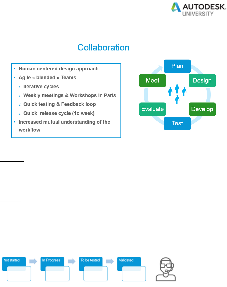
In the next section, we will show you how our team organizes itself for an optimal performance
and collaboration. The main characteristics of our collaboration are as follows:
Page 11
The team:
• GEM: Software experts with 3D formworks background
• VCF: Formwork optimization expert with Revit API background
• Autodesk Project Management & Technical Support
The tool:
For collaborating in this agile, interactive environment, VCF and Autodesk decided to work with
JIRA. This allows the team to track epics, user stories, issues and enhancements on a common
platform. Testing, Acceptance, Validation happens in one place which provides a maximum of
transparency and centralization of information. It also provides a good forum for alignment and
visualizing the progress of development, which is organized in Sprints.

Page 12
Prerequisites to the development project
Before diving into project development, it is important to state some fundamental prerequisites.
In this section, we will see what are these prerequisites.
General ideas to consider
Start with choosing the right personal for the job as project leader and product manager. You want
people with enough real-world experience to understand and emphasis all critical issues and at
the same time having the ability to abstract and leave out unnecessary details. Let them ask the
right questions to all the right people. This may steal some time from your everyday workforce.
The goal is to capture and highlight all the really important tasks and how the software should
support these.
Abstract and generalize the workflow and tasks to the right level, where it can be documented
and unambiguously discussed between software developers and product manager. This is
necessary to make the developers comprehend the critical issues in full.
Now you can decide which existing tools you want to use, and which features you need to add on
top.
Be flexible: Benefit from questions, ideas and also problems occurring during software
development to rethink your existing workflow abstraction and update it or even the workflow
itself. You don’t want to miss that chance to improve your workflow.

Page 13
VCF’s BIM workflow
VCF has built along the years some workflows and the plugin had to fit in there. In this section,
we will describe some parts of our workflow and their impact on the tool specification.
Leverage Revit strength
Vinci Construction France has compared other the years many BIM software to support its
process. Revit was chosen because of its following proven capabilities (Figure 6: Vertical
formwork layout drawing in Revit):
• Schedules for drawing quantifications: it helps visualize quantity tables directly on the
sheets, next to the drawing.
• The combination of the phasing module and parts command in Revit. The phasing module
can perform a sequence simulation and save you a huge number of graphic filters. The
parts command enables us to divide Revit components into pouring objects that can be
phased independently.
• Color filtering by attributes and legends to graphically show building construction options
and make sure that everything is up to date.
• Equipment library creation: VCF has built other the years a set of highly parametric
equipment families in Revit.
• The power of linked files associated to the parts command for a good discipline
collaboration between the Methods and the Structural Engineer: this point was important
because we didn’t want to create our pouring objects (= parts in Revit) inside the structural
Engineer Revit file, but at the same time the pouring objects should reflect the original
structural components. Revit allows us to do that out of the box: therefore, we had to
assume that the plugin is able to extract the geometry the same way, no matter if the
pouring object (= Revit part) is coming from a wall which resides in the host file or in the
linked file (Figure 7: Creating parts from a linked file).

Page 14
Figure 6: Vertical formwork layout drawing in Revit

Page 15
Figure 7: Creating parts from a linked file
Modeling rules
Because the plugin is going to read the geometry from the modeled Revit elements, it was
important to state correctly our modeling rules.
We had to specify for example which Revit categories we use to model the components that may
be casted with a vertical formwork (Figure 8: Revit categories involved in the geometry analysis).
Figure 8: Revit categories involved in the geometry analysis

Page 16
To extract the correct bill of quantities for construction planning, Methods Engineers need to
model the building vertical components with the correct pouring height: therefore, we assumed
that the plugin could directly figure out the correct formwork height based on the buildings
components modeled and could put a warning if the wall is not entirely covered (Figure 9: wall
height cutting rules).
Figure 9: wall height cutting rules
Finally, set the correct junction priority between two walls depending on their relative sequence
does matter, not only to extract a more accurate pouring volume, but also to tell the plugin the
exact starting formwork starting point on the next sequence (because there is physically a wall
already casted on a previous phase). Fortunately, Revit let you easily change the junction priority
depending on the sequence (Erreur ! Source du renvoi introuvable.).
Figure 10: Wall junction priority order in Revit
Existing families and data

Page 17
Layout an entire building with formwork families in Revit may overload the document: therefore,
it is critical to create some very lightweight families to save Revit performance. For that reason,
we chose to build a geometrical simple but highly parametric family that supports several vertical
formwork system providers just by changing some parameters value (Figure 11: One family THAT
SUPPORTS SEVERAL FORMWORK SYSTEM PROVIDERS).
Figure 11: One family THAT SUPPORTS SEVERAL FORMWORK SYSTEM PROVIDERS
If you are interested on the way we designed our equipment Revit library, there is an interesting
AU class we did in 2015 that describes in detail the process:
CS10454: Create Complex Building Site Tools with Revit Families and API

Page 18
On the other hand, we need to report all the detailed accessories involved each day for two
reasons:
- A more precise crane activity and human resources calculation.
- A better stock optimization and logistic delivery.
During the development specification phase, we decided not to rely on the families’ instances and
properties to compute the data, even though there is a shared nested component feature in Revit
that enables us to quantify nested components. Why not using it? Because today we control the
entire process by using our own families, but tomorrow these families may come directly from the
formwork system provider: this hypothetical change should have a minimum impact to our
development: to achieve this we decided to make the quantity calculation process totally
independent from the drawing. This has been managed through the catalogue files (more details
in the Assembly definition section).
Tool presentation
In this section, we will go through the key functionalities of our plugin.
Overall architecture
As you can see below (Figure 12: Overall architecture), the development has been divided into
two sections:
- The configuration mode: it runs outside of Revit and let the user define the “catalogues
files”: these are xml files that defines all the data needed for the plugin. We chose to make
this open so that we can later integrate similar system providers without changing one line
of code.
- The Revit plugin: it runs inside of Revit: it analyses the pouring geometries and their
defined phases and display all the necessary information in the “Optimization table”. This
summarized table then let the user pick an available assembly definition and assign it to
the poured objects in the drawing while checking if conditions are met. Then the stock is
automatically calculated based on the assembly instances assigned to the pouring objects
in the drawing.

Page 19
Figure 12: Overall architecture
On the following sub-sections, we will talk about each module more in depth.
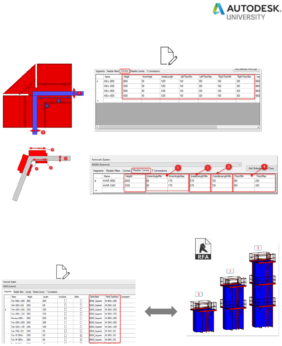
Assembly definition
The assembly definition is a set of xml files that defines several information for each formwork
system provider:
- The composition of an assembly instance: the assembly can be one sided, double sided
and composed vertically and horizontally of different standard panels, and also specific
accessories. This panel composition is used for the detailed stock calculation, the crane
activity as well as for the human resources analysis (Figure 13: Assembly definition).
- The dimensions and the rules that describes the formwork assembly and its expected
behavior. The dimensions are used to place the formwork in relation to one another in the
drawing and check if the overall formwork length and height cover correctly the pouring
segment. The rules are specifically used for the corners connections system to check if
the angle and wall thickness conditions are met (Figure 14: Dimensions and rules
description).
- The information that maps the assembly definitions to the family library: each formwork
assembly definition has an associated pre-existing family and type (Figure 15: Assembly
definition and family mapping).

Page 20
Figure 13: Assembly definition
Page 21
Figure 14: Dimensions and rules description
Figure 15: Assembly definition and family mapping
Geometry analysis

Page 22
The heart of the plugin - and probably the most complex part - is the geometry analysis. The goal
of this 2D analysis is to get the poured object footprint and then analyses the poured object
sequence and the relative sequences of all the connected poured objects:
Figure 16: 2D geometry analysis
The result should display for each poured segment its extremities condition types (blocked, open,
continuous, special connections…):
Figure 17: Poured segment extremity condition types

Page 23
These results are important for the following reasons:
- Detect situations where special corners/connection formwork can be placed (two walls
connected and within the same phase).
- Detect illegal situations where formwork placement is not allowed (Figure 18: Illegal case
example). The user is warned and can correct the pouring sequence accordingly.
- Calculate the minimum and maximum formwork length needed to cover the poured
segment (Figure 19: Formwork min/max length to cover calculation).
Figure 18: Illegal case example

Page 24
Figure 19: Formwork min/max length to cover calculation
Once the condition types and formwork length to cover are calculated for each poured segment
in the drawing, the plugin display the results on a nicely formatted table where the user can
interact with the drawing while doing its formwork optimization.
Optimization table
The optimization table (Figure 20: The optimization tableFigure 20: The optimization table) is the
main User Interface where the user does most of the interactions:
- Interaction with the geometrical analysis to collect key layout data for each poured
segment (1): phase, extremity condition types, remaining minimum formwork length to
cover, minimum formwork height…
- Interaction with the pre-existing assembly definitions to create new custom formwork
assembly definitions ready to assign
- Interaction with Revit to assign formwork assembly instances to the poured object (2).
During the assignment, feedbacks are provided to the users regarding:

Page 25
o The formwork assembly instance availability within a phase: indeed, a formwork
assembly instance cannot be used twice the same day.
o The reuse rates (3): this helps the user optimize the stock: for example, if the
assembly instance is used during 8 phases out of 10, this will result on a rate of
80%. The closer the percentage is to 100%, the better the optimization is.
- Interaction with the stock to evaluate the stock “live” and to control available assemblies.
Figure 20: The optimization table
Going beyond
Although the plugin gives to our Method Engineers full satisfaction, we plan to integrate in a near
future lots of additional useful features to the application.
Automatic optimization
Currently the user must assign manually each assembly instance to the pouring element – by
clicking a check box on the optimization table. But we found out that the plugin has technically all
the information needed (length to cover, extremity types, available formworks assemblies,
dimensions and connection rules) to process automatically the formwork assignment for all the
poured segments at once for an even greater productivity.

Page 26
Clash analysis and visual checking
Clashes between vertical formwork tierods and openings frames is an issue. The openings with
the exact frame thickness does exist in the Revit model and the exact tierods position inside the
formwork panel can be defined inside the catalogue files. With all this information, it is then
possible to run a clash analysis:
Figure 21: Tierods position inside the formwork assembly
In addition, Method Engineers needs to represent the formwork stabilizations (Figure 22: Space
requirement between formwork assemblies) as well as the formwork opening state (Figure 23:
Formwork assembly opening state) in the drawing: the reason is to visually check if the space
requirement is sufficient to position the formwork and reinforce inside the panels:
Figure 22: Space requirement between formwork assemblies

Page 27
Figure 23: Formwork assembly opening state
Integrate automatic phasing
To optimize the formwork, we need to sequence the building components first. But sometimes we
need to go back and forth between the pouring sequencing and the formwork optimization
because the two are interlinked (for example we may optimize the exact wall pouring division
based on the formwork panels sizes).
In VCF, we plan to develop a module in Revit that automatically creates and logically sequences
the pouring based on the building geometry, logistic rules as well as structural and architectural
constraints. Once this development done, we plan to link both optimizations (pouring sequencing
and formwork) together to get faster and more optimized results.

Page 28
Figure 24: automatic phasing
Run analysis on Forge for quicker results
Last year, VCF has started to develop a Forge application that allows us to bring the result of the
sequence and formwork optimization to the building site without extra cost (simple viewer on a
browser): For more information about this application, you can have a look to VCF’s presentation
this year during the Forge devCon:
FDC226365 - Moving Your Jobsite Supervision to Cloud with Forge and Revit
The final step will be to deport the Revit optimization logic on Forge: sometimes our building site
operators are facing some logistic problems on site. They need a way to quickly recalculate a
sequence and the corresponding formwork optimization to find out a solution. That final step will
complete our willing to bring the power of BIM to the building site:

Page 29
Figure 25: Deporting Revit custom optimization tools on Forge
