
Gigabyte Management Console
User's Guide
Rev. 1.0

Copyright
© 2021 GIGA-BYTE TECHNOLOGY CO., LTD. All rights reserved.
The trademarks mentioned in this manual are legally registered to their respective owners.
Disclaimer
Information in this manual is protected by copyright laws and is the property of GIGABYTE.
Changes to the specifications and features in this manual may be made by GIGABYTE
without prior notice. No part of this manual may be reproduced, copied, translated, transmitted, or
published in any form or by any means without GIGABYTE's prior written permission.
Documentation Classications
In order to assist in the use of this product, GIGABYTE provides the following types of documentation:
UserManual:detailedinformation&stepsabouttheinstallation,congurationandusethis
product(motherboard),coveringhardware,BIOSandBMCrmware.
ServiceGuide:detailedinformation&stepsabouttheinstallation,congurationanduseof
this product (server barebones), covering hardware & BIOS
Quick Installation Guide: a short guide with visual diagrams that you can reference easily for
installation purposes
Please see the support section of the online product page to check the current availability of these
documents
For More Information
Forrelatedproductspecications,thelatestrmwareandsoftware,andrelatedinformation,pleasevisit
our website at:
http://www.gigabyte.com
For GIGABYTE distributors and resellers, additional sales & marketing materials are available from our
reseller portal:
http://reseller.b2b.gigabyte.com
For further information & technical assistance, please contact your GIGABYTE sales representative.
You may also message GIGABYTE server directly by email, Facebook or twitter
Email: server[email protected]
Facebook: https://www.facebook.com/gigabyteserver
Twitter: https://twitter.com/GIGABYTEServer

- 3 -
Table of Contents
Chapter 1 Getting Started ...............................................................................................5
1-1 Software Requirement ..................................................................................... 5
1-2 GigabyteManagementConsoleNetworkConguration .................................. 6
1-3 Log In Gigabyte Management Console ............................................................ 7
1-3-1 Required Browser Settings: ......................................................................................9
1-4 Quick Button and Logged-in User .................................................................. 10
1-5 Help ................................................................................................................ 11
1-6 Menu Bar ........................................................................................................ 11
Chapter 2 Enter Gigabyte Management Console .........................................................13
2-1 Dashboard ...................................................................................................... 13
2-2 Sensor ............................................................................................................ 14
2-2-1 Sensor Detail ..........................................................................................................15
2-3 System Inventory ........................................................................................... 17
2-3-1 CPU Inventory ........................................................................................................17
2-3-2 DIMM Inventory ......................................................................................................18
2-3-3 PCI Inventory ..........................................................................................................18
2-3-4 HDD Inventory ........................................................................................................19
2-3-5 NIC Inventory ..........................................................................................................19
2-3-6 GPU Inventory ........................................................................................................20
2-4 FRU Information ............................................................................................. 22
2-5 Logs & Reports .............................................................................................. 24
2-5-1 IPMI Event Log .......................................................................................................24
2-5-2 System Log .............................................................................................................26
2-5-3 Audit Log ................................................................................................................27
2-5-4 Video Log ...............................................................................................................28
2-6 Settings .......................................................................................................... 29
2-6-1 Captured BSOD .....................................................................................................29
2-6-2 Date & Time ............................................................................................................30
2-6-3 External User Services ...........................................................................................31
2-6-4 KVM Mouse Settings ..............................................................................................42
2-6-5 Log Settings ............................................................................................................44
2-6-6 Media Redirection Settings .....................................................................................47
2-6-7 Network Settings ....................................................................................................54
2-6-8 NVMe MI Management ...........................................................................................61
2-6-9 PAM Order Settings ................................................................................................63
2-6-10 Platform Event Filter ...............................................................................................64
2-6-11 Services ..................................................................................................................73

- 4 -
2-6-12 SMTP Settings ........................................................................................................77
2-6-13 SSL Settings ...........................................................................................................80
2-6-14 System Firewall ......................................................................................................85
2-6-15 User Management ..................................................................................................95
2-6-16 Video Recording ...................................................................................................100
2-6-17 Fan Policy .............................................................................................................109
2-6-18 Power Consumption ............................................................................................. 111
2-7 Remote Control ............................................................................................ 103
2-8 Images Redirection ...................................................................................... 109
2-8-1 Remote Media ......................................................................................................110
2-9 Power Control ...............................................................................................111
2-10 Maintenance Group ...................................................................................... 112
2-10-1 BackupConguration ...........................................................................................113
2-10-2 Firmware Image Location .....................................................................................115
2-10-3 Firmware Update ..................................................................................................116
2-10-4 HPM Firmware Update .........................................................................................122
2-10-5 Firmware Information ............................................................................................125
2-10-6 PreserveConguration .........................................................................................126
2-10-7 RestoreConguration ...........................................................................................131
2-10-8 Restore Factory Defaults ......................................................................................132
2-10-9 System Administrator ............................................................................................133
2-10-10 Sign Out ................................................................................................................134

- 5 - Getting Started
1-1 Software Requirement
• Client machine with 8GB RAM.
• If the client machine has 4GB RAM, there will be lag in Video/keyboard/mouse
functionality.
•
Supported Browsers
• Chrome latest version.
• IE 11 and above.
• Firefox (with limited support).
Note: It is advisable to use Chrome or IE for H5Viewer, since Firefox has its own
memory limitations
Chapter 1 Getting Started

Getting Started - 6 -
1-2 Gigabyte Management Console Network Conguration
Follow the instruction to enable the console redirection function.
1. You can gather the IP address on the POST screen.
2. Or, Go to BIOS setup menu.
3. Select Server Management.
4. Select BMC network Conguration.
5. DeneCongurationAddresssourcetoDynamicBmcDhcporStatic.
6. Save and Exit.
7. The BMC IP Address will appear on the IPv4 Address parameter.
8. SavethecongurationandexitBIOSsetupmenu.

- 7 - Getting Started
1-3 Log In Gigabyte Management Console
To access the Gigabyte Management Console, the BMC Web utility will prompt you to enter the
User Name and Password.
Theeldsareexplainedasfollows:
For basic login to the BMC Web UI, use the following login:
• Username: admin
• Password: Refer to unique MB serial number.
NOTE!
If your motherboard / server version is older than G9 (upgrade version), then use the
following login:
Username:admin
Password: password
This serial number can be found on the serial number sticker located on the motherboard of
every GIGABYTE server motherboard and system. The unique pre-programmed password will
be the last 11 characters of the serial number. For example, for the below serial number, the
password will be “JG4P6400027

Getting Started - 8 -
GIGABYTEwillalsoafxnewstickersthatdisplaytheuniqueBMCpassword(examplebelow)to
both the product box (packaging) and to the CPU cover (for motherboards sold separately) or the
server chassis.
Please see the reference guide below / attached for where to find locations of this sticker
according to product / model type.
Products that have been implemented with this change will be indicated as version G9 on the
“Upgrade Version” sticker located on the motherboard / motherboard anti-static packaging /
server chassis / server packaging
Remember Username: Check this option to remember your login credentials.
Sign me in: After entering the required credentials, click the Sign me in to login to GUI.
I forgot my password: If you forget your password, you can generate a new one using this link.
Enter the username, click on Forgot Password link. This will send the newly generated
passwordtotheconguredEmail-IDfortheuser.

- 9 - Getting Started
1-3-1 Required Browser Settings:
Allow le download from this site: For Internet Explorer, Choose Tools ->Internet Options
->Security Tab, based on device setup, select among Internet, Local intranet, trusted sites and
restricted sites. Click Custom level.... In the Security Settings - Zone dialog opened, under
settings, find Downloads option, Enable File download option. Click OK to the entire dialog
boxes.
ForallOtherBrowsers,acceptledownloadwhenprompted.
Enable javascript for this site: The icon indicates whether the javascript setting is enabled in
browser.
Enable cookies for this site: The icon indicates whether the cookies setting are enabled in
browser.
Cookies must be enabled in order to access the website.

Getting Started - 10 -
1-4 Quick Button and Logged-in User
The user information and quick buttons are located at the top right of the Web GUI. A screenshot
of the logged-in user information is shown below.
User Information
The logged-in user information shows the logged-in user, his/her privilege and the four quick
buttons allowing you to perform the following functions:
Logged-in user and its privilege level
Thisoptionshowsthelogged-inusernameandprivilege.Therearevekindsofprivileges.
User: Only valid commands are allowed.
Operator: All BMC commands are allowed except for the configuration commands that can
change the behavior of the out-of-hand interfaces.
Administrator: All BMC commands are allowed.
No Access: Login access denied.
OEM: All OEM commands are allowed.
Notication:Clicktheicontoviewthenoticationmessages.
Refresh: Click the icon to reload the current page.
Sync: Click the icon to synchronize with Latest Sensor and Event Log updates.
Sign-out: Click the icon to log out of the Web GUI.
Warning: Click to view the warning messages.

- 11 - Getting Started
1-5 Help
Help - The Help icon (?) is Located at the top right of the each page in Web GUI. Click this help
icontoviewmoredetailedelddescriptions.
1-6 Menu Bar
The menu bar displays the following:

Getting Started - 12 -
This page intentionally left blank

- 13 - Gigabyte Server Management Console
Chapter 2 Enter Gigabyte Management Console
2-1 Dashboard
The Dashboard page gives the overall information about the status of a device.
To open the Dashboard page, click Dashboard from the menu bar. It displays the following:
Dashboard
A brief description of the Dashboard page is given below.
BMC Up Time
It indicates the Power On time.
Pending Deassertions
It lists the all pending events incurred by various sensors and occupied/available space in logs
can be viewed. To know about the pending events details, click the More info link. This navigates
to the Event Log page.
Access Logs
A graphical representation of all events incurred by various sensors and occupied/available space
in logs can be viewed, if you click on the More info link, you can view the Audit Log page.
Today & 30 Days (Event Logs)
This page displays the list of event logs occurred by the different sensors on this device. Click
Details link on Today and 30 days to view the event logs for Today and 30 days respectively.
Sensor Monitoring
It lists all the critical sensors on the device. If you click on any list sensor, you can view the
Sensor detail page with the Sensor information and Sensor Events details.

Gigabyte Server Management Console - 14 -
2-2 Sensor
The Sensor Readings page displays all the sensor related information.
To open the Sensor Readings page, click Sensor from the menu. Click on any sensor to show
more information about that particular sensor, including thresholds and a graphical representation
of all associated events.
A sample screenshot of Sensor Readings page is shown below.
The Sensor Readings page contains the following information:
In this Sensor Reading page, Live readings for all the available sensors with details like Sensor
Name, Status, Current Reading and Behavior will be appeared, else you can choose the sensor
type that you want to display from the list. Some examples for sensors are Temperature Sensors,
Fan Sensors, Watchdog Sensors and Voltage Sensors etc.
Note: Four DIMM Temp sensors are deployed for monitoring the DIMM temperature on the
system. Users must take notice that the live reading of each DIMM Temp sensor indicates the
temperatureofaDIMMgroup,notthetemperatureofaspecicDIMM.

- 15 - Gigabyte Server Management Console
Note: Four DIMM Temp sensors are deployed for monitoring the DIMM temperature on
the system. Users must take notice that the live reading of each DIMM Temp sensor
indicatesthetemperatureofaDIMMgroup,notthetemperatureofaspecicDIMM.
2-2-1 Sensor Detail
Select a particular Sensor from the Critical Sensor or Normal Sensor lists. The Sensor
Information as Live Widget and Thresholds for the selected sensor will be displayed as shown
below.
Note:For Illustrative Purpose, a sample screenshot of Sensor detail page with Change
Thresholds option is shown and explained below.
Note: Widgets are little gadgets, which provide real time information about a particular
sensor.Usercantrackasensor'sbehavioroveraspecicamountoftimeatspecic
intervals.The result will be displayed as a line graph in the widget. The session will not
expire, until the widgets gets a live data of the last widget that is kept opened.
For the selected sensor, this widget gives a dynamic representation of the readings for

Gigabyte Server Management Console - 16 -
the sensor.
There are six types of thresholds:
• Lower Non-Recoverable (LNR)
• Lower Critical (LC)
• Lower Non-Critical (LNC)
• Upper Non-Recoverable (UNR)
• Upper Critical (UC)
• Upper Non-Critical (UNC)
The threshold states could be Lower Non-critical - going low, Lower Non-critical - going high,
Lower Critical - going low, Lower Critical - going high, Lower Non-recoverable - going low, Lower
Non-recoverable - going high, Upper Non-critical - going low, Upper Non-critical - going high,
Upper Critical - going low, Upper Critical - going high, Upper Non-recoverable - going low, Upper
Non-recoverable - going high.
A graphical view of these events (Number of Entries vs. Thresholds) can be viewed as shown in
the Sensor Readings page screenshot.

- 17 - Gigabyte Server Management Console
2-3 System Inventory
The System Inventory page displays the following information:
• CPU Inventory
• DIMM Inventory
• PCI Inventory
• HDD Inventory
• NIC Inventory
• GPU Inventory (Nvidia A100 only)
A screenshot displaying the menu items under System Inventory is shown below.
A detailed description of System Inventory is given below.
2-3-1 CPU Inventory
This page displays all detected CPUs on this device. Select one CPU to see the details of
that entry or click on Expand All to view all entries in details. Click Download SMBIOS le to
downloadtheSMBIOSle.

- 18 - Gigabyte Server Management Console
2-3-2 DIMM Inventory
This page displays all detected DIMMs on this device. It allows you to see memory attributes,
individual memory details or all entries in detail by clicking on Expand All. Click Download
SMBIOS letodownloadtheSMBIOSle.
2-3-3 PCI Inventory
This page displays all detected PCI cards on this device. It allows you to see on-board PCI cards,
add-on PCI cards or all entries in detail by clicking on Expand All. Click Download SMBIOS le
todownloadtheSMBIOSle.

- 19 - Gigabyte Server Management Console
2-3-4 HDD Inventory
This page displays all detected HDDs on this device. It allows you to see on-board HDDs, add-
on HDDs or all entries in detail by clicking on Expand All. Click Download SMBIOS file to
downloadtheSMBIOSle.
2-3-5 NIC Inventory
This page displays all detected NICs on this device. It allows you to on-board NICs, add-on NICs
or all entries in detail by clicking on Expand All. Click Download SMBIOS le to download the
SMBIOSle.

- 20 - Gigabyte Server Management Console
2-3-6 GPU Inventory
This page displays all detected GPU card on this device. It allows you to view GPU card all
entries in detail by clicking on Expand All.
Detail information for GPU
• GPU Information
• Capabilities
• NVLink Information
Temperature Information for GPU
• GPU Temperature
• Extended Precision GPU Temperature
Status Information for GPU
• Accumulated Utilization
• Power Supply

- 21 - Gigabyte Server Management Console
Power Information for GPU
• Power Consumption
Clock Information for GPU
• Graphics Clock Frequency
• -Memory Clock Frequency

- 22 - Gigabyte Server Management Console
2-4 FRU Information
FRU Information page displays the BMC’s FRU device information. FRU page shows information
like Basic Information, Chassis Information, Board Information and Product Information of the
FRU device.
To open the FRU Information page, click FRU Information from the menu bar. Select a FRU
Device ID from the FRU Information section to view the details of the selected device. A
screenshot of FRU Information page is shown below.
Thefollowingeldsaredisplayedherefortheselecteddevice:
Available FRU Devices
• FRU device ID - Select the device ID from the drop down list
• FRU Device Name - The device name of the selected FRU device.
Chassis Information
• Chassis Information Area Format Version
• Chassis Type
• Chassis Part Number
• Chassis Serial Number
• Chassis Extra

Gigabyte Server Management Console - 23 -
Board Information
• Board Information Area Format Version
• Language
• Manufacture Date Time
• Board Manufacturer
• Board Product Name
• Board Serial Number
• Board Part Number
• FRU File ID
• Board Extra
Product Information
• Board Information Area Format Version
• Language
• Manufacture Date Time
• Board Manufacturer
• Board Product Name
• Board Serial Number
• Board Part Number
• FRU File ID
• Board Extra

- 24 - Gigabyte Server Management Console
2-5 Logs & Reports
The Logs & Reports page displays the following information:
• IPMI Event Log
• System Log
• Audit Log
• Video Log
A screenshot displaying the menu items under Logs & Reports is shown below.
A detailed description of Logs & Reports is given below.
2-5-1 IPMI Event Log
This page displays the list of event logs occurred by the different sensors on this device. Double
clickonarecordtoseethedetailsofthatentry.Youcanusethesensortypeorsensornamelter
optionstoviewthosespeciceventsoryoucanalsosortthelistofentriesbyclickingonanyof
the column headers.
To open the Event Log page, click Logs & Reports > IPMI Event Log from the menu bar.
A sample screenshot of Event Log page is shown below.

Gigabyte Server Management Console - 25 -
TheEventLogpageconsistsofthefollowingelds:
Filter By Date: Filtering can be done by selecting Start Date and End Date.
Note:Date should be in MM/DD/YYYY format.
By default, all log time will be displayed in BMC time zone.
Filter By Type: The category could be either All Events, System Event Records, OEM Event
Records, BIOS Generated Events, SMI Handler Events, System Management Software Events,
System Software - OEM Events, Remote Console software Events, Terminal Mode Remote
Console software Events.
Note:Once the Filter By Date and Filter type are selected, the list of events will
be displayed with the Event ID, Time Stamp, Sensor Type, Sensor Name and
Description.
Event Log Statistics: Displays the statistical graph for the selected date.
Clear Event Logs: To delete all the event logs.
Download Event Logs: To download the event logs.
Procedure
1. FromtheFilterByDateeld,selectthetimeperiodbyStart Date and End Date using
Calendar for the event categories.
2. From the Filter By Type eld,selecttheType of the event and Sensor name to view the
events for the date. The events will be displayed based on the selected time period.
3. To clear all events from the list, click Clear All Event Logs.
4. To download the event logs, click Download Event Logs.

- 26 - Gigabyte Server Management Console
2-5-2 System Log
To open the System Log page, click Logs & Reports > System Log from the menu bar. A
sample screenshot of System Log page is shown below.
A sample screenshot of Video Log page is shown below.
ToviewSystemLog,clicktheSystemLogtabtoviewallsystemevents.Entriescanbeltered
based on Filter By Date (Start Date and End Date) and Event Category like Alert, Critical, Error,
Notication,Warning,Debug,EmergencyandInformation.
Download Event Logs: To download the event logs.

- 27 - Gigabyte Server Management Console
2-5-3 Audit Log
Audit Log page will display all the system events occurred in this device that has been already
congured.
Note:LogshavetobeconguredunderSettings-> Log Settings > Advanced Log
Settings in order to display any entries.
To open the Event Log page, click Logs & Reports > Audit Log from the menu bar.
A sample screenshot of Audit Log page is shown below.
To view Audit Log, click the Audit Log tab to view all audit events for this device.
Download Event Logs: To download the event logs.

- 28 - Gigabyte Server Management Console
2-5-4 Video Log
To open the Video Log page, click Logs & Reports > Video Log from the menu bar. A sample
screenshot of Video Log page is shown below.
Note: Video Trigger Settings should be enabled, to display the Video Log page. Video Trigger
Settings can be configured under Settings -> Video Recording ->Auto Video Settings ->
Video Trigger Settings.
A sample screenshot of Video Log page is shown below.
Click on the Video Log entry to view the Video. A sample screenshot of Video Log - Video page is
shown below.
Videowillbeallowedtoplay/downloadonlyiflesizeislesserthan40MB.Browsers
have various memory restrictions, due to this browser cannot store and process data
greaterthan40MB(approximately).Iflesizeisgreaterthan40MB,userwillbenotied
with a message to use Java player Application.

Gigabyte Server Management Console - 29 -
2-6 Settings
This group of pages allows you to access various configuration settings. A screenshot of
CongurationGroupmenuisshownbelow.
A detailed description of the Settings menu is given below.
2-6-1 Captured BSOD
This page displays a snapshot of the blue screen captured if the host system crashed since last
reboot. A screenshot of Captured BSOD is shown below.
Note: KVM service should be enabled to display the BSOD screen. KVM Service can be
cong¬uredunderSettings->Services->KVM.

- 30 - Gigabyte Server Management Console
2-6-2 Date & Time
ThiseldisusedtosetthedateandtimeontheBMC.ASamplescreenshotofDate&Timeis
shown below.
TheDate&Timesectionconsistsofthefollowingelds:
Configure Date & Time: Displays Time zone list containing the UTC offset along with the
locations and Navigational line to select the location which can be used to display the exact local
time.
Select Time Zone:ThiseldisusedtosetthedateandtimeontheBMC.
Automatic Date & Time: To automatically synchronize Date and Time with the NTP Server.
Primary NTP Server:TocongureaprimaryNTPservertousewhenautomaticallysettingthe
date and time.
Secondary NTP Server:TocongureasecondaryNTPservertousewhenautomaticallysetting
the date and time.
Save:Tosavetheconguredsettings.
Note:If the timezone is selected as Manual Offset, the map selection will be disabled.
TheTime¬Zonesettingswillbereectedonlyaftersavingthesettings.

Gigabyte Server Management Console - 31 -
Procedure
1. Select the Timezone location either using drop down or Map.
2. Enable Automatic Date & Time option to enable/disable the use of NTP servers to
automatically set the date and time.
• InthePrimaryNTPServerandSecondaryNTPServerelds,specifytheNTPserversof
the device respectively.
Note: SecondaryNTPserverisoptionaleld.IfthePrimaryNTPserverisnotworking
ne,thentheSecondaryNTPServerwillbeused.
3. Click Save button to save the settings.
2-6-3 External User Services
LDAP/E-Directory Settings
The Lightweight Directory Access Protocol (LDAP)/E-Directory Settings is an application
protocol for querying and modifying data of directory services implemented in Internet Protocol (IP)
networks.
In Web GUI, LDAP is an Internet protocol that BMC can use to authenticate users. If you have
anLDAP servercongured on yournetwork, you canuseit as aneasy way toadd, manage
and authenticate BMC users. This is done by passing login requests to your LDAP Server. This
meansthatthereisnoneedtodeneanadditionalauthenticationmechanism,whenusingthe
BMC. Since your existing LDAP Server keeps an authentication centralized, you will always know
whoisaccessingthenetworkresourcesandcaneasilydenetheuserorgroup-basedpolicies
to control access.
To open External User Services page, click Settings > External User Services from the menu
bar. A sample screenshot of External User Services page is shown below.

- 32 - Gigabyte Server Management Console
To open LDAP/E-DIRECTORY Settings page, click Settings > External User Services >
LDAP/E-Directory Settings from the menu bar.
A sample screenshot of External User Services page is shown below.
TheeldsofLDAP/E-DirectorySettingspageareexplainedbelow.
General Settings:TocongureLDAP/E-DirectorySettings.OptionsareEnableLDAP/E-Directory
Authentication, IP Address, Port and Search base.
Role Groups: To add a new role group to the device. Alternatively, double click on a free slot to
add a role group.
Procedure
1. In the LDAP/E-Directory Settings page, click General Settings. A sample screenshot of
General LDAP Settings page is given below.

Gigabyte Server Management Console - 33 -
2. Click Enable LDAP/E-Directory Authentication, to enable LDAP/E-Directory Settings.
Note: Congureproperportnumber,whenSSLisenabled.
3. Select the Common Name Type as IP Address.
4. EntertheIPaddressofLDAPserverintheServerAddresseld.
Note: IP Address made of 4 numbers separated by dots as in ‘xxx.xxx.xxx.xxx’.
Each Number ranges from 0 to 255.
First Number must not be 0.
Supports IPv4 Address format and IPv6 Address format.
CongureFQDNaddress,whenusingStartTLSwithFQDN.
5. Specify the LDAP Port in the Port eld.
Note: Default Port is 389. For SSL connections, default port is 636. The Port value
ranges from 1 to 65535.
6. Specify the Bind DN that is used during bind operation, which authenticates the client to
the server.
Note: Bind DN is a string of 4 to 64 alpha-numeric characters.
It must start with an alphabetical character.
Special Symbols like dot(.), comma(,), hyphen(-), underscore(_), equal-to(=) are allowed.
Example: cn=manager, ou=login, dc=domain, dc=com
7. Enter the password in the Passwordeld.
Note: Password must be at least 1 character long.
Blank space is not allowed
Thiseldwillnotallowmorethan48characters.
8. Enter the Search Base.TheSearchbaseallowstheLDAPservertondwhichpartof
the external directory tree to be searched. The search base may be something equivalent
to the organization, group of external directory.

- 34 - Gigabyte Server Management Console
Note: Search base is a string of 4 to 63 alpha-numeric characters.
It must start with an alphabetical character.
Special Symbols like dot(.), comma(,), hyphen(-), underscore(_), equal-to(=) are allowed.
Example: ou-login, dc-domain, dc-com
9. SelectAttributeofUserLogintondtheLDAP/E-Directoryserverwhichattributeshould
be used to identify the user.
Note:It only supports cn or uid.
10. Select CA Certicate FilefromtheBrowseeldtoidentifythecerticateofthetrusted
CA certs.
11. Select the CA Certicate Filetondtheclientcerticatelename.
12. Select Private Keytondtheclientprivatekeylename.
Note:Allthe3lesarerequired,whenStartTLSisenabled.
13. Click Save to save the settings.
To add a new Role Group
1. In the LDAP/E-Directory Settings page, click Role Groups and select a blank row.
2. Click Add Role Group or alternatively double click on the blank row to open the Add
Role group page as shown in the screenshot below.
3. IntheGroupNameeld,enterthenamethatidentiestherolegroup.

Gigabyte Server Management Console - 35 -
Note: Role Group Name is a string of 255 alpha-numeric characters.
Special symbols hyphen and underscore are allowed.
4. IntheGroupDomaineld.EntertheRoleGroupDomainwheretherolegroupislocated.
Note: Domain Name is a string of 4 to 64 alpha-numeric characters.
It must start with an alphabetical character.
Special Symbols like dot(.), comma(,), hyphen(-), underscore(_), equal-to(=) are allowed.
Example: cn=manager, ou=login, dc=domain, dc=com
5. Inthe Group Privilegeeld, enterthelevel ofprivilege (User,Administrator, Operator,
None) to assign to this role group.
6. Select one or both of the required options
• KVM Access
• VMedia Access
7. Click Save to save the new role group and return to the Role Group List.
Active Directory Settings
An active directory is a directory structure used on Microsoft Windows based computers and
servers to store information and data about networks and domains. An active directory (sometimes
referred to as AD) does a variety of functions including the ability to provide information on
objects. It also helps to organize these objects for easy retrieval and access, allows access by
end users and administrators and allows the administrator to set security up for the directory.
ActiveDirectoryallowsyoutoconguretheActiveDirectoryServerSettings.Thedisplayedtable
showsanyconguredRoleGroups andtheavailableslots.Youcanmodify,addor deleterole
groups from here. Group domain can be the AD domain or a trusted domain. Group Name should
correspond to the name of an actual AD group.
Note: To view the page, you must be at least a User and to modify or add a group, you must be
an Administrator.

- 36 - Gigabyte Server Management Console
To open Active Directory Settings page, click Settings > External User Settings > Active
Directory from the menu bar. A sample screenshot of Active Directory Settings page is shown
below.
TheeldsofActiveDirectorypageareexplainedbelow.
General Settings:This optionis used tocongureActive DirectoryGeneral Settings. Options
are Enable Active Directory Authentication, Secret User Name, Secret Password, User Domain
name, and up to three Domain Controller Server Addresses.
Role Groups: To add a new role group to the device. Alternatively, double click on a free slot to
add a role group.

Gigabyte Server Management Console - 37 -
Procedure
Entering the details in General Active Directory Settings page:
1. Click on General Settings to open the General Active Directory Settings page.
2. In the Active Directory Settings page, check or uncheck the Enable Active directory
Authentication check box to enable or disable Active Directory Authentication
respectively.
Note:If you have enabled. Active Directory Authentication, enter the required information
to access the Active Directory server.
3. Specify the Secret user name and password in the Secret User Name and Secret
Passwordeldsrespectively.
Note: Secret username/password for AD is not mandatory. When secret username &
password is empty, Authentication fails will be always treated as Invalid Password error.
For Invalid Password error PAM will not try other Authentication Methods. So it is
recommended to keep AD in the last location in PAM order.
User Name is a string of 1 to 64 alpha-numeric characters.
It must start with an alphabetical character.
It is case-sensitive.
Special characters like comma, period, colon, semicolon, slash, backslash, square
brackets,
Blank space is not allowed, angle brackets, pipe, equal, plus, asterisk, question mark,

- 38 - Gigabyte Server Management Console
ampersand, double quotes, space are not allowed.
Password must be at least 6 character long and will not allow more than 127 characters.
4. SpecifytheDomainNamefortheuserintheUserDomainNameeld.E.g.MyDomain.
com
5. CongureIPaddresses inDomain Controller Server Address1, Domain Controller
Server Address2 and Domain Controller Server Address3
Note: IP address of Active Directory server: At least one Domain Controller Server
Addressmustbecongured.IPAddressmadeof4numbersseparatedbydotsasin
“xxx.xxx.xxx.xxx”.
Each number ranges from 0 to 255.
First number must not be 0.
Domain Controller Server Addresses will supports IPv4 Address format and IPv6
Address format.
6. Click Save to save the entered settings and return to Active Directory Settings page.
Role Groups
To open Role Group page, click Settings > External User Settings > Active Directory > Role
Groups from the menu bar. A sample screenshot of Role Groups page is shown below.
TheeldsofRoleGrouppageareexplainedbelow.
Role Group Name:ThenamethatidentiestherolegroupintheActiveDirectory.
Note: Role Group Name is a string of 64 alpha-numeric characters.
Special symbols hyphen and underscore are allowed.

Gigabyte Server Management Console - 39 -
Group Name:ThisnameidentiestherolegroupinActiveDirectory.
Note: Role Group Name is a string of 64 alpha-numeric characters.
Special symbols hyphen and underscore are allowed.
Group Domain: The domain where the role group is located.
Note:Domain Name is a string of 255 alpha-numeric characters.
Special symbols hyphen, underscore and dot are allowed.
Group Privilege: The level of privilege to assign to this role group.
KVM Access: To provide access to KVM for AD authenticated role group user.
VMedia Access: To provide access to VMedia for AD authenticated role group user.
To add a new Role Group
1. In the Active Directory Settings page, select a Role Group and click Add Role Group or
alternatively double click on the blank row to open the Add Role group page as shown in
the screenshot below.
2. In the Group Name field, enter the name that identifies the role group in the Active
Directory.
Note: Role Group Name is a string of 64 alpha-numeric characters.
Special symbols hyphen and underscore are allowed.
3. IntheGroupDomaineld,enterthedomainwheretherolegroupislocated.
Note: Domain Name is a string of 255 alpha-numeric characters. - Special symbols
hyphen, underscore and dot are allowed.
4. In the Group Privilegeeld,enterthelevelofprivilegetoassigntothisrolegroup.

- 40 - Gigabyte Server Management Console
5. Select the required options
• KVM Access
• VMedia Access
6. Click Save to add the new role group and return to the Role Group List.
To Delete a Role Group
1. In the Role Groups Page, select the row that you wish to delete
2. Click Delete Role Group.
RADIUS Settings
RADIUS is a modular, high performance and feature-rich RADIUS suite including server, clients,
development libraries and numerous additional RADIUS related utilities.
In Web GUI, this page is used to set the RADIUS Authentication.
To open RADIUS Settings page, click Settings > External User Settings > RADIUS Settings
from the menu bar. A sample screenshot of RADIUS Settings page is shown below.
TheeldsofGeneralRADIUSSettingspageareexplainedbelow.
Enable RADIUS Authentication: Option to enable/disable RADIUS authentication.
Server Address: The IP address of RADIUS server.
Note: IP Address (Both IPv4 and IPv6 format).
FQDN(FullyQualiedDomainName)format.
Port: The RADIUS Port number.
Note: Default Port is 1812.
Port value ranges from 1 to 65535.
Secret: The Authentication Secret for RADIUS server.
Note:Thiseldwillnotallowmorethan31characters.
Secret must be at least 4 characters long.

Gigabyte Server Management Console - 41 -
Blank space is not allowed.
Enable KVM Access:ThiseldprovidesaccesstoKVMforRADIUSauthenticatedusers.
Enable VMedia Access:ThiseldprovidesaccesstoVMediaforRADIUSauthenticatedusers.
Save:Tosavetheconguredsettings.
Procedure
1. Enable the RADIUS Authentication check box to authenticate the RADIUS.
2. Click Advanced RADIUS Settings. This opens the Radius Authorization window as
shown below.
Note:ForAuthorizationPurpose,conguretheRadiususerwithVendorSpecic
Attribute in Server side.
Example: 1
testadmin Auth-Type: =PAP, Cleartext-Password:=”admin”
Auth-Type:=PAP,Vendor-Specic=”H=4”
Example: 2
test operator Auth-Type: = PAP, Cleartext-Password:= “operator”
Auth-Type:=PAP,Vendor-Specic=”H=3”
IfyouchangetheVendor-Specicvalueinserverthenyoushouldchangethesame
values in this page.
3. Click Save to save the changes made.

Gigabyte Server Management Console - 42 -
2-6-4 KVM Mouse Settings
In BMC Web GUI, Redirection Console handles mouse emulation from local window to remote
screenineither ofthreemethods.Userhastobe anAdministrator tocongurethis option.To
view the Supported Operating Systems for Mouse Mode, click Mouse Mode.
To open KVM Mouse setting page, click Settings >KVM Mouse Setting from the menu bar.
A sample screenshot of KVM Mouse Settings page is shown below.
TheeldsofKVMMouseSettingspageareexplainedbelow.
Relative Positioning (Linux): Relative mode sends the calculated relative mouse position
displacement to the server.
Absolute Positioning (Windows): The absolute position of the local mouse is sent to the server.
Other Mode (SLES-11 OS Installation): To have the calculated displacement from the local mouse
in the center position sent to the server.
Save: To save the current changes.
Procedure
1. Choose either of the following as your requirement:
• Set mode to Absolute
Note: Applicable for all Windows versions, versions above RHEL6, and versions above
FC14
• Set mode to Relative
Note: Applicable for all Linux versions, versions less than RHEL6, and versions less
than FC14
• Mode to Other Mode

Gigabyte Server Management Console - 43 -
Note: Recommended for SLES-11 OS Installation
2. Click Save button to save the changes made.

- 44 - Gigabyte Server Management Console
2-6-5 Log Settings
In BMC Web GUI, System and Audit log page displays a list of system logs and audit logs
occurred in this device.
To open Log Settings page, click Settings > Log Settings from the menu bar. A sample
screenshot of Log Settings page is shown below.
TheeldsofLogSettingspageareexplainedbelow.
SEL Settings Policy
To open SEL Settings Policy page, click Settings > Log Settings > SEL Settings Policy from
the menu bar. A sample screenshot of SEL Settings Policy page is shown below.

Gigabyte Server Management Console - 45 -
Advanced Log Settings
To open Advanced Log Settings page, click Settings > Log Settings > Advanced Log Settings
from the menu bar. A sample screenshot of Advanced Log Settings Policy page is shown below.
Thispageisusedtocongurethelogpolicyfortheeventlog.Theeldsareasfollows.
Enable System Log:ThiseldistoenableordisabletheSystemLogs.
Location:SpeciestheLocationforsystemlogs,whetheritshouldbepreservedinaLocal Log
or on a Remote Log.
Note:Localleresidesat/var/log/
File Size:Thiseldistospecifythesizeoftheleinbytesiftheselectedlogtypeislocal.
Note:Sizerangesfrom3to65535.Loglesarerotatedwhentheygrowbiggerthan
size bytes mentioned, with regards for the last rotation time interval (1 minute).
Rotate Count:Tobackuptheloginformationinbackuples.
Note: Values supported are 0 and 1.
Whenloginformationexceedsthelesize,theoldloginformationisautomatically
movedtobackuplesbasedontherotatecountvalue.Ifrotatecountiszero,thenold
log information gets cleared permanently.
File Size and Rotate Count options will be available only when Local Log is enabled.
Remote Log Server:ThiseldistospecifytheRemoteserveraddresstologthesystemevents.
Note: Server address will support the following:
IPv4 address format.
FQDN(Fullyqualieddomainname)format.
Remote Server Port:ThiseldistospecifytheRemoteServerportaddresstologthesystem
events.
Note: Remote Log Server and Remote Server Port options will be available only when
Remote Log is enabled.

- 46 - Gigabyte Server Management Console
Enable Audit Log: To enable or disable the audit log.
Save: To save the current changes.
Procedure
1. In the System Logeld,enableordisabletheoption.
2. Select the Log type: Local Log or Remote Log.
3. IfLocallogisselected,enterthelesize intheFile Sizeeldand rotatecountinthe
Rotate Counteld.
Note:IfRemotelogisselected,theeldslesizeandrotatecountneednotbe
mentioned.
4. If remote log is selected specify the Server Address of the remote server, where the
system events are logged.
5. In the Audit Logeld,checkorunchecktheEnable option as desired.
6. Click Save to save the changes.
Steps to congure the remote server to enable syslogging
Note: This example uses FC13 as the remote machine to log syslog.
On FC machine, disable the following lines for UDP in /etc/rsyslog.conf:
1. MODLOAD imudp
2. UDPSERVER 514

Gigabyte Server Management Console - 47 -
2-6-6 Media Redirection Settings
Thispageis usedtocongure themediainto BMCforredirection.Toopen MediaRedirection
page, click Settings > Media Redirection Settings from the menu bar.
A sample screenshot of Media Redirection page is shown below.

- 48 - Gigabyte Server Management Console
TheeldsofMediaRedirectionpageareexplainedbelow.
• General Settings
• VMedia Instance Settings
• Remote Session
• Active Redirections
General Settings
ThisoptionisusedtocongureGeneralMediaSettings.
To open General Media Settings section, click Settings > Media Redirection Settings > General
Settings.
Remote Media Support: To enable or disable Remote Media support, check/uncheck the ‘Enable’
check box.
If it is selected, then the following Remote Media types will be displayed.
• Mount CD/DVD
• Mount Harddisk
Onselectingtheindividualmediatypes,itsrespectivecongurationswillbedisplayed.Youcan
conguredifferentsettings for differentRemoteMediatypes.Asamplescreenshot of General
Settings page is shown below.

Gigabyte Server Management Console - 49 -
Note: You can also select all the media types simultaneously.
Server Address for CD/DVD Images: Displays the address of the server where the
remote media images are stored.
Same settings for Harddisk Images: Enable/Disable to select same media type data
congurationsforalltheremotemediatypes.
Mount Harddisk: Enable/Disable to Mount Harddisk.
Server Address for Harddisk Images: Address of the server where the remote media images
are stored.
Path in server: Source path to the remote media images.
Share Type for Harddisk: To Select Share Type for Floppy.
Domain Name, Username, and Password: If share Type is Samba(CIFS), then enter user
credentials to authenticate on the server.
VMedia Instance Settings
ThispageisusedtocongureVirtualMediadevicesettings.ToopenVMediaInstanceSettings
page, click Settings > Media Redirection Settings > VMedia Instance Settings from the menu
bar.
A sample screenshot of VMedia Instance Settings page is shown below.

- 50 - Gigabyte Server Management Console
Thefollowingeldsaredisplayedinthispage:
CD/DVD device instances: The number of CD/DVD devices supported for Virtual Media
redirection.
Harddisk instances: The number of harddisk devices supported for Virtual Media redirection.
Remote KVM CD/DVD device instances: The number of CD/DVD devices supported for KVM
Virtual Media redirection.
Remote KVM Hard disk instances: The number of Hard disk devices supported for KVM Virtual
Media redirection.
Emulate SD Media as USB disk to Host: To emulate SD Media on BMC as a USB device to
Host Server.
Power Save Mode: To enable or disable the virtual USB devices visibility in the host. If this option
is enabled, Virtual media devices will be connected to the Host machine only at the instance
launching KVM session. If this option is disabled, Virtual media devices will remain connected to
the host machine all the time irrespective of KVM session status.
Save:Tosavetheconguredsettings.
Note: VirtualMediacongurationchangeswillrestartallthemediaservices.So
congurationchangeswillbeblockedwhenanyactivemediaredirectionispresent.
Procedure
1. Select the number of Floppy devices, CD/DVD devices, Harddisk devices and Remote
KVM Floppy, CD/DVD and Hard disk Devices from the respective drop-down list.
Note: Maximum of four devices can be added in Floppy, CD/DVD and Harddisk drives.

Gigabyte Server Management Console - 51 -
2. Select the Emulate SD Media as USB disk to Host option to enable/disable the SD
card support in the host.
3. Check the Power Save Mode option to enable/disable the Virtual USB devices visibility
in the host.
4. Click Save to save the changes made else click Reset to reset the previously saved
values.
Note: When KVM is launched from Standalone Application, if there are two device
panels for each device, and when you click the Connect button, then the redirected
device panel will be disabled.
Unmounting device will make the driver disconnect device when using Auto Attach.
Hence, when unmounting one USB key, the other USB key will be disconnected and
then reconnected.
Remote Session
InBMCWeb,thispageisusedtocongureRemoteSessioncongurationsettings.“KVMSingle
Port Application” is enabled by default. On disabling, “KVM Single Port Application”, “Encrypt
H5Viewer KVM packets” will be enabled by default. On enabling “KVM Single Port Application”,
“Encrypt H5Viewer KVM packets” will be disabled if it is enabled already.
To open Remote Session page, click Settings > Media Redirection Settings > Remote
Session from the menu bar.
A sample screenshot of Remote Session page is shown below.

- 52 - Gigabyte Server Management Console
TheeldsofCongureRemoteSessionpageareexplainedbelow.
KVM Single Port Application: To Enable/Disable single port support by runtime. On changing
thisconguration,KVMandVMediaSessionswillberestarted.Ifthissupportisenabled,KVM
session will not use its dedicated port whereas both Web and KVM sessions will be established
only via Web Port. If this support is disabled, KVM and Web sessions will use their own dedicated
ports respectively.
Enable KVM Encryption: To Enable/Disable Enable KVM Encryption for the next redirection
session. If KVM Encryption is enabled, the KVM session will use the Secure port which has been
conguredinSettings->ServicesPage.
Note: If “Allow Non-Secure communication for KVM/Media” in the PRJ option is enabled,
then KVM/Media can use non-secure communication. i.e. The KVM or Media Encryption
will be able to disable.
If KVM Encryption is disabled, the KVM session will use the Non-Secure port which has
beenconguredinSettings->Services Page.
Note: This option is disabled if Single Port is enabled.
Keyboard Language: This option is used to select the keyboard supported languages.
Retry Count: This option is used to retry the redirection session for certain number of attempts.
Retry Time Interval(Seconds): This option is used to give time interval for each attempts.
Server Monitor OFF Feature Status: To enable/disable Server Monitor OFF. If this option is
enabled, you can Lock or Unlock the Local host monitor from the remote KVM window. If this
option is disabled, you cannot Lock or Unlock the Local host monitor from the remote KVM
window.
Automatically OFF Server Monitor, When KVM Launches: To enable/disable Automatically
OFF Server Monitor, When KVM Launches.
Save: To save the current changes.
Note: It will automatically close the existing remote redirection either KVM or Virtual
media sessions on Single Port enable/Disable.
Note: Installation of Operating System on the servers via BMC CD ISO image over
remote KVM may take 1 to 2 hours.
Procedure
1. Check or uncheck the KVM Single Port Application option to enable Single Port
Application support in BMC.
2. Choose the Keyboard Language from the list of keyboard supported languages.
3. Enter a value in the Retry Counteldtosetthe numberof attemptsfor retryingthe
redirection session.
4. Enter a value in the Retry Time Interval (Seconds)eldtogivetimeintervalforeach
attempts.
5. Check the Server Monitor OFF Feature Status check box to enable Local Monitor ON/

- 53 - Gigabyte Server Management Console
OFF command during runtime.
6. Check the Automatically OFF Server Monitor, When KVM Launches check box to
automatically Lock the local monitor during H5Viewer launch.
7. Click Save to save the current changes.
Active Redirections
This page displays a list of Media which are being redirected currently. It shows current status
and other basic information about the Media.
Thefollowingeldsaredisplayedinthispage.
Media Type: The type Media devices (CD/DVD) supported for Active Redirections.
Media instances: The number of Media devices supported for Active Redirections.
Client Type: The type Media devices (CD/DVD) supported for Active Redirections.
Image Name: The name of Media devices supported image for Active Redirections.
Redirection Status: The status Media for Active Redirections.
Client IP: The IP of the connected Media devices (CD/DVD) supported for Active Redirections.
Note: Local/Remote Media connection will use loopback socket for communication. So
‘~’ symbol will be displayed for loopback ip(127.0.0.1 (or) ::1 ) in media session information
page.

Gigabyte Server Management Console - 54 -
2-6-7 Network Settings
The Network Settings page is used to configure the network settings for the available LAN
channels. It also allows users to manage the DNS settings or configure Network Controller
Sideband Interface of a device. To open the Network Settings page, click Settings > Network
Settings from the menu bar.

- 55 - Gigabyte Server Management Console
Network IP Settings
To open Network IP Settings page, click Settings > Network Settings > Network IP Settings
from the menu bar. A sample screenshot of Network IP Settings page is shown below.
TheeldsofNetworkIPSettingspageareexplainedbelow.
Enable LAN: To enable or disable the LAN Settings.
LAN Interface: Lists the LAN interfaces.
MAC Address:ThiselddisplaystheMACAddressofthedevice.Thisisareadonlyeld.
Enable IPv4: This option is to enable/disable the IPv4 settings in the device.
Enable IPv4 DHCP: This option is to enable IPv4 DHCP support for the selected interface.
IPv4 Address, IPv4 Subnet Mask, and IPv4 Default Gateway:Theseeldsareforspecifying
thestaticIPv4address,SubnetMaskandDefaultGatewaytobeconguredtothedevice.
Note: IP Address made of 4 numbers separated by dots as in “xxx.xxx.xxx.xxx”.
Each Number ranges from 0 to 255.
First Number must not be 0.
Enable IPv6:ToEnable/DisabletheIPv6congurationsettings.
Enable IPv6 DHCP:ToEnable/DisabletheIPv6settingsinthedevice.Itdynamicallycongures
IPv6addressusingDHCP(DynamicHostCongurationProtocol).
IPv6 Index:TospecifyastaticIPv6Indextobeconguredtothedevice.E.g.:0
IPv6 Address:TospecifyastaticIPv6addresstobeconguredtothedevice.E.g.:2004::2010

Gigabyte Server Management Console - 56 -
Subnet Prex length:TospecifythesubnetprexlengthfortheIPv6settings.
Note: Value ranges from 0 to 128.
Default Gateway: Specify v6 default gateway for the IPv6 settings.
Note: IfcorefeatureIPV6_COMPLIANCEisenabled,theIPV6defaultGatewayeldwill
not be displayed.
Enable VLAN: To enable/disable the VLAN support for selected interface.
VLAN ID:TheIdenticationforVLANconguration.
Note: Value ranges from 2 to 4094.
VLAN Priority:ThepriorityforVLANconguration.
Note:
Value ranges from 0 to 7.
7 is the highest priority for VLAN.
Save: To save the entries.
Procedure
1. Check Enable LAN to enable LAN support for the selected interface.
2. Select the LAN Interfacetobecongured.
3. Check Enable IPv4 to enable IPv4 support for the selected interface.
4. Check Enable IPv4 DHCPtodynamicallycongureIPv4addressusingDHCP.
5. Ifthe eldis disabled, enterthe IPv4 Address, IPv4 Subnet Mask and IPv4 Default
Gateway intherespectiveelds.
6. InIPv6Conguration,ifyouwishtoenabletheIPv6settings,checkEnable IPv6.
7. If the IPv6 setting is enabled, enable or disable the option Enable IPv6 DHCP.
8. Iftheeldisdisabled,entertheIPv6 Address, Subnet Prex length and IPv6 Index in
thegiveneld.
9. InVLANConguration,ifyouwishtoenabletheVLANsettings,checkEnable LAN.
10. Enter the VLAN IDinthespeciedeld.
11. 11. Enter the VLAN Priorityinthespeciedeld.
12. Click Save to save the entries.

- 57 - Gigabyte Server Management Console
DNS Conguration
The Domain Name System (DNS) is a distributed hierarchical naming system for computers,
services, or any resource connected to the Internet or a private network. It associates the
information with domain names assigned to each of the participants. Most importantly, it
translatesdomainnamesmeaningfultohumansintothenumerical(binary)identiersassociated
with networking equipment for the purpose of locating and addressing these devices worldwide.
The DNS Server settings page is used to manage the DNS settings of a device.
To open DNS Server Settings page, click Settings > Network Settings > DNS Conguration
fromthemenubar.AsamplescreenshotofDNSCongurationpageisshownbelow.

Gigabyte Server Management Console - 58 -
Domain Name Service Conguration
DNS Enabled:Toenable/disablealltheDNSServiceCongurations.
mDNS Enable:Toenable/disablethemDNSSupportCongurations.
Host Name Settings: Choose either Automatic or Manual settings.
Host Name: It displays host name of the device. If the Host setting is chosen as Manual, then
specify the host name of the device.
Note: Value ranges from 1 to 64 alpha-numeric characters.
Special characters ‘-’(hyphen) and ‘_’(underscore) are allowed.
It must not start or end with a ‘-’(hyphen). IE browsers won't work correctly if any part of
the host name contain underscore (_)character.
BMC Registration Settings
BMC Interface: Options to register the BMC through the Interfaces (eth0ð1).
Register BMC: To register BMC through registration method.
Registration Method
Options to register the BMC are through NS Update or DHCP Client FQDN or Hostname.
TSIG Conguration
Both: Check this option to modify TSIG authentication for both interfaces.
Eth 0&1:
• TSIG Authentication Enabled: Check this box to enable TSIG authentication while
registeringDNSviansupdate.SeparateTSIGlescanbeuploadedforeachLAN
interface.
• Current TSIG Private File:TheinformationofCurrentTSIGprivatelealongwith
its uploaded date/time will be displayed (readonly).
• New TSIG Private File:BrowseandnavigatetotheTSIGprivatele.
Note:TSIGleshouldbeofprivatetype.
Domain Setting: Select whether the domain interface will be configured manually or
automatically.
• Automatic-IfyouSelectAutomatic,theDomainNamecannotbeconguredasit
willbedoneautomatically.Theeldwillbedisabled.
• Manual - If the Domain setting is chosen as Manual, then specify the domain name
of the device.
Note: If you select “Automatic” it displays the Domain Interface option. If
you select “Manual” it displays “Domain name”.
• Domain Name: It displays the domain name of the device.
Domain Name Server Setting
Automatic - If you select Automatic “DNS Interface” option should be explained.
Manual -SpecifytheDNS(DomainNameSystem)serveraddresstobeconguredfortheBMC.

- 59 - Gigabyte Server Management Console
IP Priority:
• If IP Priority is IPv4, it will have 2 IPv4 DNS servers and 1 IPv6 DNS server.
• If IP Priority is IPv6, it will have 2 IPv6 DNS servers and 1 IPv4 DNS server.
Note:ThisisnotapplicableforManualconguration.
DNS Server 1, 2 & 3
TospecifytheDNS(DomainNameSystem)serveraddresstobeconguredfortheBMC.
Note: IPv4 Addresses should be given in dotted decimal representation.
IPv6 Addresses are supported and must be global unicast addresses.
DNS Server Address will support the following:
• IPv4 Address format.
• IPv6 Address format.
Save: To save the current changes.
Procedure
1. InDomainNameServiceConguration,EnableDNSService.
• Check the option DNS EnabledtoenablealltheDNSServiceCongurations.
2. Choose the Host Name Setting either Automatic or Manual.
Note: If you choose Automatic, you need not enter the Host Name and if you choose
Manual, you need to enter the Host Name.
3. Enter the Host NameinthegiveneldifyouhavechosenManualConguration.
4. Under Register BMC, choose the BMC’s network port to register with DNS settings.
Check Register BMC option to register with DNS settings.
• Nsupdate - Choose Nsupdate option to register with DNS server using nsupdate
application.
• DHCP Client FQDN - Choose DHCP Client FQDN option to register with DNS
Server using DHCP option 81.
• Hostname - Choose Hostname option to register with DNS server using DHCP
option 12.
Note: Hostname option should be selected, if the DHCP client FQDN option is not
supported by DHCP server.
5. Check Both option to modify TSIG authentication for both interfaces (eth0&1).
6. In Eth 0&1 TSIG Conguration, Check TSIG Authentication Enabled option to enable/
disable TSIG authentication while registering DNS via nsupdate.
• ThecurrentlenamewillbedisplayedinCurrentTSIGPrivateleinfoeld.
• Toviewanewone,clickNewTSIGprivateletobrowseandnavigatetotheTSIG
privatele.
7. In the Domain Settings,
• Select the domain settings (Automatic or Manual).
• EntertheDomainNameinthegiveneldiftheoption“Manual”isbeingselectedin
domainsettingseld.

- 60 - Gigabyte Server Management Console
8. In Domain Name Server Setting,
• Select the DNS Name Server Setting.
• Choose the IP Priority, either IPv4 or IPv6.
• Enter the DNS Server address.
9. In DNS Server1, DNS Server2 and DNS Server3, enter the server addresses to be
conguredfortheBMC.
10. Click Save to save the entries.

Gigabyte Server Management Console - 61 -
2-6-8 NVMe MI Management
NVMe-MI Subsystem Information
In selecting any particular NVMe SSD, the corresponding NVMe SSD Subsystem Information,
Port Information, Subsystem Health Status Poll and Set Health Status Change will be displayed.
Click on 'Clear All' button to clear all Composite Controller Status Flags at a time under
'Subsystem Health Status Poll' information tab.
Click on 'Clear' button to clear individual Composite Controller Status Flags under 'Set Health
Status Change' information tab.

Gigabyte Server Management Console - 62 -
NVMe-MI Vital Product Data
On selecting any particular NVMe SSD, the corresponding SSD's Product Information will be
displayed. It displays detailed information like IPMI Version, Product Name, Part Model, Product
Version etc.. of the NVMe SSD. On Click of 'Multi Record Informaion' tab NVMe MultiRecord and
NVMe PCIe Port MultiRecord will be displayed.

Gigabyte Server Management Console - 63 -
2-6-9 PAM Order Settings
ThispageisusedtocongurethePAMorderingforuserauthenticationintotheBMC.
To open PAM Ordering page, click Settings > PAM Order Settings from the menu bar. A sample
screenshot of PAM Order page is shown below:
TheeldsofSetttings > PAM Ordering page are explained below.
PAM Module: It shows the list of available PAM modules supported in BMC.
Note: It is recommended to not to keep same username for different PAM modules.
If Authentication fails, the reason of fail could be invalid User or Invalid Password.
If Radius Authentication fails, we can't differentiate whether it is invalid user or invalid
password. So it is always treated as Invalid username error and PAM will try other
Authentication Methods.
If AD contains secret username & password as empty, Authentication fails will be always
treated as Invalid Password error. For Invalid Password error PAM will not try other
Authentication Methods. So it is recommended to keep AD in the last location in PAM
order.
Procedure
1. Select the required PAM module and click and drag the required PAM module. It can be
moved UP or DOWN to change its arrangement order.
2. Click Save to save any changes made.
Note: Wheneverthecongurationismodied,thewebserverwillberestarted
automatically. Logged-in session will be logged out.

- 64 - Gigabyte Server Management Console
2-6-10 Platform Event Filter
Platform Event Filter (PEF) provides a mechanism for configuring the BMC to take selected
actions on event messages that it receives or has internally generated. These actions include
operations such as system power-off, system reset, as well as triggering the generation of an
alert.
InBMCWebGUI,thePEFManagementisusedtocongurethefollowing:
• Event Filters
• Alert Policies
• LAN Destinations
To open PEF Management Settings page, click Settings > Platform Event Filter from the menu
bar. Each tab is explained below.

Gigabyte Server Management Console - 65 -
Event Filters
A PEFimplementationisrecommended to provideat least 40entriesin the eventlter table.
Asubsetoftheseentriesshouldbepre-conguredforcommonsystemfailureevents,suchas
over-temperature, power system failure, fan failure events, etc. Remaining entries can be made
available for ‘OEM’ or System Management Software configured events. Note that individual
entriescanbetaggedasbeingreservedforsystemuse-sothisratioofpre¬conguredentries
torun-timecongurableentriescanbereallocatedifnecessary.
TheeldsofPlatformEventFiltersTabareexplainedbelow.
ThispagecontainsPre-congured40EventswithPEFIDs.
Procedure
1. ClicktheEventFilterssectiontoconguretheeventltersintheavailableslots.
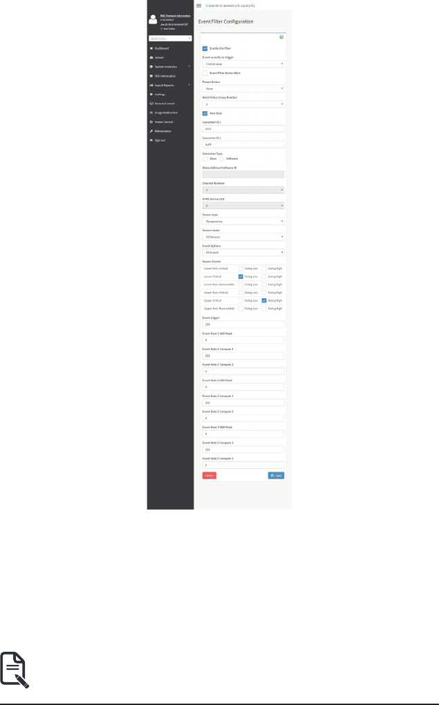
2. To Add an Event Filter entry, select a free section to open the Event Filter entry page. A
samplescreenshotofEventFilterCongurationpageisshownbelow.
- 66 - Gigabyte Server Management Console
IntheEventFilterCongurationsection:
• InEnablethislter,checkthisoptiontoenablethePEFsettings.
• In Event Severity to trigger, select any one of the Event severity from the list.
• CheckEventFilterActionAlerttoenablealertsforeventlteractions.
• Select any one of the Power Action either Power down, Power reset or Power cycle
from the drop down list
• ChooseanyoneoftheconguredAlertPolicyGroupNumberfromthedropdown
list.
Note:AlertPolicyhastobecongured-underSettings->PEF->Alert Policy.

Gigabyte Server Management Console - 67 -
• CheckRawDataoptiontolltheGeneratorIDwithrawdata.
• Generator ID 1eldisusedtogiverawgeneratorID1datavalue.
• Generator ID 2eldisusedtogiverawgeneratorID2datavalue.
Note: In RAWdataeld,specifyhexadecimalvalueprexwith‘0x'.
• In the Event Generator section, choose the event generator as Slave Address - if
event was generated from IPMB. Otherwise as System Software ID - if event was
generated from system software.
• In the Slave Address/Software IDeld,specifycorrespondingI2CSlaveAddress
or System Software ID.
• Choose the particular Channel Number that event message was received over.
Or choose ‘0’ if the event message was received via the system interface, primary
IPMB, or internally generated by the BMC.
• Choose the corresponding IPMB Device LUN if event generated by IPMB.
• Select the Sensor Typeofsensorthatwilltriggertheeventlteraction.
• In the SensorNameeld,choosetheparticularsensorfromthesensorlist.
• Choose Event OptiontobeeitherAllEventsorSensorSpecicEvents.
• IntheSensorEventseld,choosethetypeofeventlevels.
• Event TriggereldisusedtogiveEvent/Readingtypevalue.
Note: Value ranges from 1 to 255.
• Event Data 1 AND Maskeldisusedtoindicatewildcardedorcomparedbits.
Note: Value ranges from 1 to 255.
• Event Data 1 Compare 1 & Event Data 1 Compare 2eldsareusedtoindicate
whether each bit position’s comparison is an exact comparison or not.
Note: Value ranges from 1 to 255.
• Event Data 2 AND MaskeldissimilartoEventData1ANDMask.
• Event Data 2 Compare 1 & Event Data 2 Compare 2eldsaresimilartoEvent
Data 1 Compare 1 and Event Data 1 Compare 2 respectively.
• Event Data 3 AND MaskeldissimilartoEventData1ANDMask.
• Event Data 3 Compare 1 & Event Data 3 Compare 2eldsaresimilartoEvent
Data 1 Compare 1 and Event Data 1 Compare 2 respectively.
3. Click Savetosavethechangesandreturntoeventlterlist.
4. Click Deletetodeletetheexistinglter.

- 68 - Gigabyte Server Management Console
Alert Policies
ThispageisusedtoconguretheAlertPolicyforthePEFconguration.Youcanadd,deleteor
modify an entry in this page.
TheeldsofPlatformEventFilter-AlertPoliciessectionareexplainedbelow.
Policy Group Number:DisplaysthePolicynumberoftheconguration.
Enable this alert: To enable or disable the policy settings.
Policy Action: To choose any one of the Policy set values (0-5) from the list.
0 - Always send alert to this destination.
1 - If alert to previous destination was successful, do not send alert to this destination. Proceed to
next entry in this policy set.
2 - If alert to previous destination was successful, do not send alert to this destination. Do not
process any more entries in this policy set.
3 - If alert to previous destination was successful, do not send alert to this destination. Proceed to
next entry in this policy set that is to a different channel.
4 - If alert to previous destination was successful, do not send alert to this destination. Proceed to
next entry in this policy set that is to a different destination type.
LAN Channel: To choose a particular channel from the available channel list.
DestinationSelector:Tochooseaparticulardestinationfromthecongureddestinationlist.
Note:LANDestinationhastobecongured-underSettings->Platform Event Filters
>LAN Destinations.
Event Specic Alert String:Tospecifyanevent-specicAlertString.
Alert String Key: To specify which string is to be sent for this Alert Policy entry.
Save: To save the Alert Policies entries.
Delete:TodeletetheselectedconguredAlertPolicy.
Procedure
1. IntheAlertPoliciesSection,select theslot forwhich youhave toconguretheAlert
policy. That is, In the Alert Policies page, if you have chosen Alert Policy Group Number
as4,youhavetocongurethe4thslot(theslotwithPolicyNumber4)intheAlertPolicy
Tab.

Gigabyte Server Management Console - 69 -
2. Select the slot and click on the empty slot to open the Alert Policies page as shown in
the screenshot below.
3. Select Policy Group Number from the drop-down list.
4. Check Enable this alert to enable the policy settings.
5. Choose any of the Policy Action from the list.
6. Choose particular LAN Channel from the available channel list.
7. In the Destination Selector, choose particular destination from the configured
destination list.
Note: LANDestinationhastobeconguredunderSettings-> Platform Event Filters-
>LAN Destinations.
That is if you select the number 4 for destination selector in Alert Policy Entry page, then
youhavetocongurethe4thslot(LANDestinationNumber4)intheLANDestinations
tab.
8. Enable Event Specic Alert String,iftheAlertpolicyentryisEventSpecic.
9. In the Alert String Keyeld, chooseanyonevalue thatisusedtolookuptheAlert
String to send for this Alert Policy entry.
Note: UsingWebUI,AlertstringscannotbeconguredbutoptionforEventSpecic
alert strings can be enabled/disabled. There is an option to select only the alert string
keys,butalertstringshastobeconguredusingIPMICommand(SetPEFCong
Parameter 'Alert String").
10. Click Save to save the new alert policy and return to Alert Policy list.
11. Click Deletetodeleteaconguration.

- 70 - Gigabyte Server Management Console
LAN Destinations
ThispageisusedtoconguretheLANdestinationofPEFconguration.Asamplescreenshotof
LAN Destination page is given below.
TheeldsofPlatformEventFilters-LANDestinationsareexplainedbelow.
SelectanyemptyslottocongureLANDestinations.
Select the LAN Channel: To select the LAN Channel number
LAN Channel: Displays LAN Channel Number for the selected slot (read-only).
LAN Destination: Displays ID for setting Destination Selector of Alert Policy (read-only).
Destination Type: Destination type can be either an SNMP Trap or an E-mail alert. For E-mail
alerts,thefourelds- SNMPDestinationAddress,BMC UserName, EmailsubjectandEmail
messageneedstobelled.TheSMTPserverinformationalsohastobeadded-underSettings
->SMTP Settings.ForSNMPTrap,onlytheSNMPDestinationAddresshastobelled.

Gigabyte Server Management Console - 71 -
SNMP Destination Address: If Destination type is SNMP Trap, then enter the IP address of the
system that will receive the alert. Destination address will support the following:
• IPv4 address format.
• IPv6 address format.
BMC User Name: If Destination type is Email Alert, then choose the user to whom the email
alert has to be sent. Email address for the user has to be configured under Settings-->User
Management.
Email Subject & Email Message:These eldsmustbe conguredifemail alertischosen as
destinationtype.Anemail will besent tothecongured emailaddressof theuser in caseof
anyseverityeventswithasubjectspeciedinsubjecteldandwillcontainthemessageeld’s
contentastheemailbody.Theseeldsarenotapplicablefor‘AMI-Format’emailusers.
Note: UsershouldbeconguredunderSettings-->UserManagement
Save: To add a new entry to the device. Alternatively, double click on a free slot.
Delete:TodeletetheselectedconguredLANDestination.
Procedure
1. In the LAN Destinationssection, choosethenumber ofslotstobecongured.This
should be the same number of slot that you have selected in the Alert Policies -
DestinationSelectoreld.ThatisifyouhavechosentheDestinationSelectoras4inthe
AlertPoliciespageofAlertPoliciestab,thenyouhavetocongurethe4thslotofLAN
Destination page.
2. Select the slot and click on the empty slot. This opens the LAN Destination entry.

- 72 - Gigabyte Server Management Console
3. In the LAN Channel Numbereld,the LANChannel Numberfor theselected slotis
displayedandthisisareadonlyeld.
4. In the LAN Destinationeld,thedestinationforthenewlyconguredentryisdisplayed
andthisisareadonlyeld.
5. In the Destination Typeeld,selecttheoneofthetypes.
6. In the SNMP Destination Addresseld,enterthedestinationaddress.
7. If the destination type is Email alert, select the BMC User Name from the list of users.
Note: E-mailaddressshouldbeconguredunderSettings-->User Management.
8. In the Email Subjecteld,enterthesubject.
9. In the Email Messageeld,enterthemessage.
10. Click Save to save the new LAN destination and return to LAN destination list.
11. Click Deletetodeleteaconguration.
12. Click Send Test Alert tosendsamplealerttocongureddestination.
Note: TestalertcanbesentonlywithenabledSMTPconguration.SMTPsupportcan
be enabled under Settings->SMTP Settings.

Gigabyte Server Management Console - 73 -
2-6-11 Services
This page displays the basic information about services running in the BMC. Only Administrator
can modify the service.
To open Services page, click Settings > Services from the menu bar. A sample screenshot of
Services page is shown below.
TheeldsofServicespageareexplainedbelow.
Services: Displays service name of the selected slot (read-only).
Status: Displays the current status of the service, either active or inactive state.
Interfaces: It shows the interface in which service is running.
Nonsecure Port:Thisportisusedtocongurenonsecureportnumberfortheservice.
• Web default port is 80
• KVM default port is 7578
• CD Media default port is 5120
• FD Media default port is 5122
• HD Media default port is 5123
• Telnet default port is 23
• SOLSSH default port is 52123
Note: SSH service will not support non secure port. If single port feature is enabled,
KVM, CD Media, FD Media and HD Media ports cannot be edited. Port value ranges
from 1 to 65535.
Secure Port:Usedtoconguresecureportnumberfortheservice.
• Web default port is 443

- 74 - Gigabyte Server Management Console
• KVM default port is 7582
• CD Media default port is 5124
• FD Media default port is 5126
• HD Media default port is 5127
• SSH default port is 22
Note: Telnet service and SOLSSH will not support secure port. If single port feature is
enabled, KVM, CD Media, FD Media and HD Media ports cannot be edited. Port value
ranges from 1 to 65535.
Port listening status on various feature settings:
Single port
enabled
Single port
disabled
Only KVM
encryption
enabled
Only Media
encryption
enabled
Both KVM
and Media
encryption
enabled
Adviser
(video server)
7578 (LP)
7578 (LP)
7578 (EO)
7578 (LP)
7578 (EO)
7578(LP)
7578 (EO)
7578(LP)
7582 (EO)
Cdserver 5120 (LP)
5120 (LP)
5120 (EO)
5120 (LP)
5120 (EO)
5120 (LP)
5124 (EO)
5120 (LP)
5124 (EO)
Fdserver 5122 (LP)
5122 (LP)
5122 (EO)
5122 (LP)
5122 (EO)
5122 (LP)
5126 (EO)
5122 (LP)
5126 (EO)
Hdserver 5123 (LP)
5123 (LP)
5123 (EO)
5123 (LP)
5123 (EO)
5123 (LP)
5127 (EO)
5123 (LP)
5127 (EO)
Note: LP - Loopback, EO - Exposed Outside.
Theadviserwillalwaysbelisteningtoloopbackaswellaskvmconguredinterface
as mentioned in the above table. So that the H5Viewer client can connect to the video
server.
Themediaserverswillbelisteningtoloopbackaswellasconguredinterfaceas
mentioned in the above table. So that the lmedia/rmedia and H5Viewer/JViewer client
can connect to the media servers.
Timeout: Displays the session timeout value of the service. For web, SSH and telnet service,
usercancongurethesessiontimeoutvalue.
Note: Web timeout value ranges from 300 to 1800 seconds.
KVM timeout value ranges from 300 to 1800 seconds.
SSH and Telnet timeout value ranges from 60 to 1800 seconds.
SSH and Telnet timeout value ranges from 60 to 1800 seconds.
SSHandtelnetservicewillbeusingthesametimeoutvalue.IfyoucongureSSH
timeout value, it will be applied to telnet service also and vice versa.

Gigabyte Server Management Console - 75 -
If KVM is launched then the web session timeout will not take effect.
Maximum Sessions: Displays the maximum number of allowed sessions for the service.
Active Sessions: To view the current active sessions for the service.
Procedure to view the Active Sessions:
1. Click View Icon ( ) to view the details about the active sessions for the service.
2. This opens the Active Session screen (for example - Service Sessions) as shown in the
screenshot below.
Session Type: Displays the type of the active sessions.
User: Displays the name of the user.
Client IP:DisplaystheIPaddressesthatarealreadyconguredfortheactivesessions.
Privilege: Displays the access privilege of the user.
3. Select a slot and click Terminate icon ( ) to terminate the particular session of the service.
To modify the existing services:
4. SelectaslotandclickEditicon()tomodifythecongurationoftheservice.
Note:Wheneverthecongurationismodied,theservicewillberestartedautomatically.
User has to close the existing opened session for the service if needed.

- 76 - Gigabyte Server Management Console
Procedure to modify the existing services:
1. SelectaslotandclickEditicon()tomodifythecongurationoftheservice.
Note: Wheneverthecongurationismodied,theservicewillberestartedautomatically.
User has to close the existing opened session for the service if needed.
2. This opens the Service Conguration screen as shown in the screenshot below.
3. Service Nameisareadonlyeld.
4. Activate the Current State by enabling the Active check box.
Note: Interfaces, Non-secure port, Secure port, Time out and Maximum Sessions will not
be active unless the current state is active.
5. Choose any one of the available interfaces from the Interface Name drop-down list.
6. EntertheNonsecureportnumberintheNon-securePorteld.
7. Enter the Secure Port Number in the Secure Porteld.
8. Enter the timeout value in the Timeout eld.
Note: The values in the Maximum Sessionseldcannotbemodied.
9. Click Save to save all changes you have made, else click Cancel to exit.

Gigabyte Server Management Console - 77 -
2-6-12 SMTP Settings
Simple Mail Transfer Protocol (SMTP) is an Internet standard for electronic mail (e-mail)
transmission across Internet Protocol (IP) networks.
UsingBMCWebGUI,youcanconguretheSMTPsettingsofthedevice.
To open SMTP Settings page, click Settings > SMTP Settings from the menu bar. A sample
screenshot of SMTP Settings page is shown below.
TheeldsofSMTPSettingspageareexplainedbelow.
LAN Interface: Displays the list of LAN channels available
Sender Email ID: A valid ‘Sender Address’ to indicate the BMC, whenever e-mail is sent.
Primary Server Name: The ‘Machine Name’ of the BMC, from where the e-mail is sent.
Note: Machine Name is a string of maximum 15 alpha-numeric characters.
Space, special characters are not allowed.
Primary SMTP Support: To enable/disable SMTP support for the BMC.
Primary SMTP Port: To specify the SMTP Normal Port.
Primary Secure SMTP Port: To specify the SMTP Secure Port.
Note: For Primary SMTP Port - Default Port is 25, and the Port value ranges from 1 to
65535.
For Primary Secure SMTP Port - Default Port is 465, and the Port value ranges from 1 to
65535.

- 78 - Gigabyte Server Management Console
Primary Server IP: The IP addressoftheSMTPServer.Itisamandatoryeld.
Note: IP Address made of 4 numbers separated by dots as in “xxx.xxx. xxx.xxx”.
Each Number ranges from 0 to 255.
First Number must not be 0.
Supports IPv4 Address format and IPv6 Address format.
Primary SMTP Authentication: To enable/disable SMTP Authentication.
Note: SMTP Server Authentication Types supported are:
• CRAM-MD5
• LOGIN
• PLAIN
If the SMTP server does not support any one of the above authentication types, the user will get
an error message stating “Authentication type is not supported by SMTP Server.”
Primary Username: Enter username to access SMTP Accounts.
Note: User Name can be of length 4 to 64 alpha-numeric characters, dot(.), dash(-), and
underline(_).
It must start with an alphabet.
Other Special Characters are not allowed.
Primary Password: Enter password for the SMTP User Account.
Note: Password must be at least 4 characters long.
Blank space is not allowed.
Thiseldwillnotallowmorethan64characters.
Primary SMTP STARTTLS Enable: To enable STARTTLS support for the SMTP Client.
• Upload SMTP CA Certicate File:Filethat containsthecerticate ofthetrusted
CAcerts.CACERTkeyleshouldbeofpemtype,LOGIN
• Upload SMTP Certicate File:Clientcerticatelename.CERTkeyleshouldbe
of pem type.
• Upload SMTP Private Key:Clientprivatekeylename.SMTPkeyleshouldbeof
pem type.
Note: To enable STARTTLS support, the respective SMTP support option should be
enabled.
Secondary SMTP Support:ItliststheSecondarySMTPServerconguration.Itisanoptional
field. If the Primary SMTP server is not working fine, then it uses Secondary SMTP Server
conguration.
Note: Options of Secondary SMTP Support are same as Primary SMTP Support.
Save:TosavethenewSMTPserverconguration.

Gigabyte Server Management Console - 79 -
Procedure
1. Select the LAN Interface from the drop-down list.
2. Enter the Sender Email IDinthespeciedeld.
3. Check Primary SMTP Support option to enable SMTP support for the BMC.
4. Enter the Machine Name of the SMTP Server in the Primary Server Name.
Note: - Machine Name is a string of maximum 15 alpha-numeric characters.
Space, special characters are not allowed.
5. Enter IP address of the SMTP Server in the Primary Server IPeld.Itisamandatory
eld.
6. Enter the Primary SMTP Portinthespeciedeld.
7. Enter the Primary Secure SMTP Port inthespeciedeld.
8. Enable the check box Primary SMTP Authentication if you want to authenticate SMTP
Server.
9. Enter your Primary User name and Primary Passwordintherespectiveelds.
10. Enable the check box Primary SMTP SSLTLS Enable to send data through secure Port.
Note: If this option is selected, STARTTLS option and Normal Port will be hidden.
11. Check the Secondary SMTP Support option to enable Secondary SMTP support for the
BMC.
12. Enter the Secondary Server Name, Secondary Server IP, Secondary SMTP Port and
Secure Port valuesintherespectiveelds.
13. Enable the check box SMTP Server Authentication if you want to authenticate SMTP
Server.
14. Enter your Secondary User name and Password intherespectiveelds.
15. Enable the check box Secondary SMTP SSLTLS to send data through secure Port.
Note: If this option is selected, STARTTLS option and Normal Port will be hidden.
16. Click Save to save the entered details.

- 80 - Gigabyte Server Management Console
2-6-13 SSL Settings
The Secure Socket Layer protocol was created by Netscape to ensure secure transactions
between web servers and browsers. The protocol uses a third party, a Certicate Authority (CA),
to identify one end or both end of the transactions.
Using BMC Web GUI, configure SSL certificate into the BMC. Using this, the device can be
accessed in a secured mode.
ToopentheSSLCerticateCongurationpage,clickSettings>SSLSettingsfromthemenubar.
There are three tabs in this page.
• Upload SSL Certicateoptionisusedtouploadthecerticateandprivatekeyle
into the BMC.
• Generate SSL CerticateoptionisusedtogeneratetheSSLcerticatebasedon
congurationdetails.
• View SSL Certificate option is used to view the uploaded SSL certificate in
readable format.
AsamplescreenshotofUploadSSLCerticatepageisshownbelow.

Gigabyte Server Management Console - 81 -
TheeldsofSSLSettings-UploadSSLSettingstabareexplainedbelow.
Current Certicate:Currentcerticateanduploadeddate/timewillbedisplayed(read-only).
New Certicate:Certicateleshouldbeofpemtype
Current Private Key: Current Private key information will be displayed (read-only).
New Private Key:Privatekeyleshouldbeofpemtype
Upload:TouploadtheSSLcerticateandprivacykeyintotheBMC.
Note: After successful upload, HTTPs service will restart to use the newly uploaded SSL
certicate.
TheeldsofSSLSettings-GenerateSSLCerticateareexplainedbelow.
Common Name(CN):Commonnameforwhichcerticateistobegenerated.
• Maximum length of 64 characters.
• It is a string of alpha-numeric characters.
• Special characters ‘#’ and ‘$’ are not allowed.
Organization(O):Organizationnameforwhichthecerticateistobegenerated.
• Maximum length of 64 characters.
• It is a string of alpha-numeric characters.
• Special characters ‘#’ and ‘$’ are not allowed.
Organization Unit(OU):Overallorganization sectionunitname forwhichcerticate istobe
generated.
• Maximum length of 64 characters.
• It is a string of alpha-numeric characters.
• Special characters ‘#’ and ‘$’ are not allowed.

- 82 - Gigabyte Server Management Console
City or Locality(L): City or Locality of the organization (mandatory).
• Maximum length of 128 characters.
• It is a string of alpha-numeric characters.
• Special characters ‘#’ and ‘$’ are not allowed.
State or Province(ST): State or Province of the organization (mandatory).
• Maximum length of 64 characters.
• It is a string of alpha-numeric characters.
• Special characters ‘#’ and ‘$’ are not allowed.
Country(C): Country code of the organization (mandatory).
• Only two characters are allowed.
• Special characters are not allowed.
Email Address: E-mail Address of the organization (mandatory).
Valid for:Validityofthecerticate.
• Value ranges from 1 to 3650 days.
Key Length:Thekeylengthbitvalueofthecerticate.
Save:TogeneratethenewSSLcerticate.
Note: HTTPsservicewillgetrestarted,tousethenewlygeneratedSSLcerticate.

Gigabyte Server Management Console - 83 -
TheeldsofSSLSettings-ViewSSLCerticateareexplainedbelow.
Basic Information: This section displays the basic information about the uploaded SSL
certicate.Itdisplaysthefollowingelds:
• Version Serial Number
• Signature Algorithm
• Public Key
• Issuer Common Name(CN)
• Issuer Organization(O)
• Issuer Organization Unit(OU)
• Issuer City or Locality(L)
• Issuer State or Province(ST)
• Issuer Country(C)
• Issuer E-mail Address
• Valid From
• Valid Till

- 84 - Gigabyte Server Management Console
Procedure
1. ClicktheUploadSSLCerticatetab,BrowsetheNewCerticateandNewPrivatekey.
2. ClickUploadtouploadthenewcerticateandprivatekey.
3. InGenerateSSLCerticate,enterthefollowingdetailsintherespectiveelds:
• The Common Name forwhichthecerticateistobegenerated.
• The Organizationforwhichthecerticateistobegenerated.
• The Organization Unit nameforwhichcerticatetobegenerated.
• The City or Locality of the organization
• The State or Province of the organization
• The Country of the organization
• The Email address of the organization.
• ThenumberofdaysthecerticatewillbevalidintheValid Foreld.
4. Choose the Key Lengthbitvalueofthecerticate
5. Click Savetogeneratethecerticate.
6. Click View SSLCerticatetabtoview theuploadedSSLcerticate inuserreadable
format.
Note: OnceyouUpload/Generatethecerticates,onlyHTTPsservicewillgetrestarted.
You can now access your Web securely using the following format in your IP Address
eldfromyourInternetbrowser:https://<yourBMC'sIPaddresshere>
For example, if your BMC's IP address is 192.168.0.30, enter the following:
https://192.168.030
Pleasenotethe<s>after <http>.Youmustacceptthecerticatebeforeyouareableto
access your Web.

Gigabyte Server Management Console - 85 -
2-6-14 System Firewall
InMegaRAC GUI, the System Firewallpage allows you to conguretherewall settings.The
rewallrulecanbesetforanIPorrangeofIPAddressesorPortnumbers.Toviewthispage,you
mustatleastbeanoperator.Onlyadministratorscanaddordeletearewall.
To open System Firewall page, click Settings > System Firewall from the menu bar.
General Firewall Settings
Click General Firewall Settings page. A sample screenshot of General Firewall Settings page is
shown below.

- 86 - Gigabyte Server Management Console
To View Existing Firewall Settings
Click General Firewall Settings > Existing Firewall Settings icon. A blank page will be opened
if you did not add anything in “Add Firewall Settings”. If any settings are added, then the added
rule will be listed in “Existing Firewall Settings” page. A sample screenshot of Existing Firewall
Settings page is shown below.
The Existing Firewall Settings page allows you to remove any particular Existing Firewall
Settings.

- 87 - Gigabyte Server Management Console
Procedures
1. Click General Firewall Settings > Existing Firewall Settings icon. A sample screenshot of
Existing Firewall Settings page is shown below.
• Block All: The blocked incoming IP’s and Port’s can be viewed.
• Flush All:Toushallthesystemrewallrules(Read-Only).
• SelectTimeouttoenableordisablerewallruleswithtimeout.
• Time Out :TherespectiverewallruleeffectStartTime,EndDate,StartTime,EndTimewill
be displayed.
• Delete:ToDeletethesystemrewallrules.

Gigabyte Server Management Console - 88 -
Add Firewall Settings
Click General Firewall Settings > Add Firewall Settings. This opens the Add Firewall Settings
page as shown below.
1. Select Block All to block all the incoming IP’s and Port’s.
2. Select Flush Alltoushallthesystemrewallrules.
3. Select Timeouttoenableordisablerewallruleswithtimeout.
4. Enter Start Timetostarttherespectiverewallruleeffectfromthistime.
5. Enter End Timetoendtherespectiverewallruleeffectfromthistime.
Note: The time should be in the dd-mm-yy:hh-mm format.
6. Click Save to save the changes made else click Cancel to go back to the previous
screen.

- 89 - Gigabyte Server Management Console
IP Address Firewall Rules
Click IP Firewall Rules page. A sample screenshot of IP Firewall Rules page is shown below.
TheeldsofIP Address Firewall tab are explained below.
To View Existing IP Rules or a range of IP Addresses
Click Settings > System Firewall > IP Address Firewall Rules > Existing IP Rules. A blank
page will be opened if you did not add anything in “Add IP Rule”. If any rule is added, then the
added rule will be listed in “Existing IP Rules” page.
A sample screenshot of Existing IP Rules page is shown below.
The Existing IP Rules page allows you to remove any particular Existing IP Rules.
Procedures
1. Select the Existing IP Rules you want to remove.
2. Click on Delete to remove the selected Existing IP Rules.

Gigabyte Server Management Console - 90 -
IP Single (or) Range Start-ToshowtheconguredPortAddressorRangeofPorts.
IP Range End-ToshowtheconguredPortAddressorRangeofPorts.
Enable Timeout - To enable/disable Timeout.
Start Date-Therespectiverewallruleeffectwillstartfromthisdate.
Start Time -Therespectiverewallruleeffectwillstartfromthistime.
End Date-Therespectiverewallruleeffectwillendfromthisdate.
End Time -Therespectiverewallruleeffectwillendfromthistime.
Rule - To indicate the current setting of the listed Port or Range of Port rules (Allow or Block)
status.
Delete - To delete the selected slot.
Procedures
1. Click Settings > System Firewall > IP Address Firewall Rules > Add New IP Rule to
add a new IP or range of IP address.

- 91 - Gigabyte Server Management Console
2. In the Add new rule for IP page, Enter the IP address and a range of IP addresses in
the IP Single or IP Range Starteld.
Note: IP Address will support IPv4 Address format only:
IPv4 Address made of 4 numbers separated by dots as in xxx.xxx.xxx.xxx.
Each number ranges from 0 to 255.
First number must not be 0.
IPv6 Address made of 8 groups of 4 Hexadecimal digits separated by colon as in
xxxx:xxxx:xxxx:xxxx:xxxx:xxxx:xxxx:xxxx.
3. Enter IP range end value in the IP Range Endeld.
4. Enable Timeout toenablerewallruleswithtimeout.
5. Enter Start Date tostarttherespectiverewallruleeffectfromthisdate.
6. Enter End Date toendtherespectiverewallruleeffectfromthisdate.
7. Enter Start Timetostarttherespectiverewallruleeffectfromthistime.
8. Enter End Timetoendtherespectiverewallruleeffectfromthistime.
Note: The date and time should be in the YYYY/MM/DD and hh-mm format respectively.
9. Determine the rule to block or accept.
10. Click Save to save the changes made.

Gigabyte Server Management Console - 92 -
Port Firewall Rules
Click Port Firewall Rules page. A sample screenshot of Port Firewall Rules page is shown
below.
TheeldsofPortFirewallRulestabareexplainedbelow.
To view Existing Port Rules
Click Settings > System Firewall > Port Firewall Rules > Existing Port Rules. A blank page
will be opened if you did not add anything in “Add New port Rule”. If any rule is added, then the
added rule will be listed in “Existing Port Rules” page.
A sample screenshot of Existing Port Rules is shown below.
The Existing Port Rules page allows you to remove any particular Existing Port Rules.

- 93 - Gigabyte Server Management Console
Procedures
1. Select the Existing Port Rules you want to remove.
2. Click on Delete to remove the selected Existing Port Rules.
TheeldsofSystemFirewall-ExistingPortRulespageareexplainedbelow.
Port Single (or) Range Start-TocongurethePortorRangeofPortAddresses.
Port Range End-TocongurethePortorRangeofPortAddresses.
Protocol-ThiseldspeciestheprotocolsfortheconguredPortorPortRanges.
Network Type - This field specifies the affected network type for the particular Port or Port
Ranges.
Enable Timeout-Toenableordisablerewallruleswithtimeout.
Start Date-Therespectiverewallruleeffectwillstartfromthistime.
Start Time-Therespectiverewallrulewillstartfromthistime.
End Date-Therespectiverewallruleeffectwillendonthisdate.
End Time-Therespectiverewallrulewillendatthistime.
Rule - To indicate Allow or Block status.
Delete-Todeletetheentrytotherewallruleslist.

Gigabyte Server Management Console - 94 -
Procedure to add Port/Range of ports
1. To add a new range of Port address, click the Add button
2. In the Add new rule for Port window, enter the port number or a range of port numbers
in the Port Single (or) Range Starteld.
3. Enter the end value in the Port Range Endeld.
4. Select the Protocol to be either TCP or UDP or Bot.
5. Select the Network Type. It may be IPv4 or IPv6 or Both.
6. Select Timeouttoenableordisablerewallruleswithtimeout.
7. Enter Start Timetostarttherespectiverewallruleeffectfromthistime.
8. Enter Start Datetostarttherespectiverewallruleeffectfromthisdate.
9. Enter End Datetoendtherespectiverewallruleeffectonthisdate.
10. Enter End Timetoendtherespectiverewallruleeffectatthistime.
Note: The time should be in the YYYY/MM/DD:hh-mm format.
11. Select the Rule to determine the rule to Block or Allow.
12. Click Save to save the changes made.

- 95 - Gigabyte Server Management Console
2-6-15 User Management
In BMC Web GUI, the User Management page allows you to view the current list of user slots for
the server. You can add a new user and modify or delete the existing users.
To open User Management page, click Settings > User Management from the menu bar. A
sample screenshot of User Management page is shown below.
Click user icon ( ) and select any free slot to add a new user from the User Management main
page.
Note: The Free slots are shown as “Disabled” in all columns for the slot.
TheeldsofUserManagementpageareexplainedbelow.
User ID: Displays the ID number of the user.
Note: The list contains a maximum often users only.
User Name: Displays the name of the user.
User Access: To enable or disable the access privilege of the user.
Network Privilege: Displays the network access privilege of the user.
SNMP Status: Displays if the SNMP status for the user is enabled or Disabled.
E-mail ID: Displays e-mail address of the user.
Add User: To add a new user.
Delete User: To delete an existing user.

Gigabyte Server Management Console - 96 -
Procedure to add a new User
1. To add a new user, select a free section and click on the empty section. This opens the
Add User screen as shown in the screenshot below.
2. EnterthenameoftheuserintheUserNameeld.
Note: User Name is a string of l to 16 alpha-numeric characters.
It must start with an alphabetical character.
It is case-sensitive.
Special characters ‘-’(hyphen), ‘_’(underscore), ‘@’(at sign) are allowed.
For 20 Bytes password, LAN session will not be established.
3. Set Password Size for the new password.
4. In the Password and Conrm Password elds,enterandconrmyournewpassword.
Note: Password should be the combination of alphabets, numbers, symbol and upper
case characters.
Blank space is not allowed.
Thiseldwillnotallowmorethan16/20charactersbasedonPasswordsizeeldvalue.
Thiseldwillnotallowthebelowmentionedcharacters.
The password should be a string, if you try to set password using “ipmitool user set
password”.

- 97 - Gigabyte Server Management Console
Hex Char
00 NUL ‘\0’
01 SOH (start of heading)
02 STX (start of text)
03 ETX (end of text)
04 EOT (end of transmission.)
05 ENQ (enquiry)
06 ACK (acknowledge)
07 BEL ‘\a’ (bell)
08 BS ‘\b’ (backspace)
09 HT ‘\t’ (horizontal lab)
0A LF ‘\n' (new Line)
0B VT ‘\v’ (vertical tab)
0C FF ‘\f’ (form feed)
0D CR ‘\r’ (carriage ret)
0E SO (shift out)
0F SI (shift in)
10 DLE (data link escape)
11 DC1 (device control 1 )
12 IDC2 (device control 2)
13 DG3 (device control 3)
14 DC4 (device control 4)
15 NAK (negative ack.)
16 SYN (synchronous idle)
17 ETB (end of trans. blk)
18 CAN (cancel)
19 EM (end of medium)
19 EM (end of medium)
1A SUB (substitute)
1B ESC (escape)
1C FS(leseparator)
1D GS (group separator)
1E RS (record separator)
1F US (unit separator)
20 SPACE
7F DEL

Gigabyte Server Management Console - 98 -
5. Enable or Disable the Enable User Access Privilege.
Note: Enabling User Access will intern assign the IPMI messaging privilege to user.
It is recommended that the IPMI messaging option should be enabled for the user to
enable the User Access option, while creating User through IPMI.
6. IntheNetworkPrivilegeandSerialPrevilegeelds,selecttheprivilegesassignedtothe
user which could be Administrator, Operator, User, OEM or None.
7. Check KVM Access to assign the KVM privilege for the user.
8. Check VMedia Access assign the VMedia privilege for the user.
Note: It is recommended that the privileges support to KVM and VMedia should be
provided only to the ADMIN user and shouldn't be provided to USER and OPERATOR
privilege level users. The Admin user can provide the privilege support to USER and
OPERATOR privilege level users at their own risk.
VMedia Privilege only restricts initiating / starting media redirection. If a device is already
being redirected and attached to the host, then in host it will be visible as normal device.
Hence, it will be accessible to all the KVM sessions, which includes ‘KVM Privilege only’
sessions as well.
9. Check the SNMP Access check box to enable SNMP access for the user.
Note: Passwordeldismandatory,ifSNMPStatusisenabled.
10. Choose the SNMP Access level option for user from the SNMP Access level (SHA or
MD5) drop-down list. Either it can be Read Only or Read Write.
11. Choose the SNMP Authentication Protocol (SHA or MD5) to use for SNMP settings
from the drop down list.
Note: Passwordeldismandatory,ifAuthenticationprotocolischanged.
12. Choose the Encryption algorithm to use for SNMP settings from the SNMP Privacy
protocol (AES or DES) drop-down list.
13. In the Email ID eld,entertheemailIDoftheuser.Iftheuserforgetsthepassword,the
newpasswordwillbemailedtotheconguredemailaddress.
Note: SMTPServermustbeconguredtosendemails.
Email Format: Two types of formats are available:
• AMI-Format: The subject of this mail format is ‘Alert from (your Host name)’. The
mail content shows sensor information, ex: Sensor type and Description.
• Fixed-Subject Format: This format displays the message according to user's
setting. You must set the subject and message for email alert.
14. In the Upload SSH Keyeld,clickBrowseandselecttheSSHkeyle.
Note: SSHkeyleshouldbeofpubtype.
15. Click Save to save the new user and return to the users list.

- 99 - Gigabyte Server Management Console
To Modify User
1. To modify the existing user, click on the active user tab. This opens a User screen as
shown in the screenshot below.
2. Check Change Password, if you wish to change the existing Password.
3. Follow the steps (3 to 15) of Procedure to add a new User.
4. Click Save to save the changes and return to the users list.
5. Click Delete to delete the user.

Gigabyte Server Management Console - 100 -
2-6-16 Video Recording
The Video Recording consists of the following:
1. Auto Video Settings
• Video Trigger Settings
• Video Remote Storage
• Pre-Event Video Recordings
2. SOL Settings
• SOL Trigger Settings
• SOL Video Remote Storage
• SOL Recorded Video
3. JAVA SOL
A sample screenshot of the Video Recording is given below.
A detailed description of the menu items are given below.
Auto Video Settings
The Auto Video Settings page allows you to configure the events that will trigger auto video
recording function of the KVM server and view the current list of user slots for the server. You can
add a new user and modify or delete the existing users.
Thispage is usedto congure theeventsthat will triggerauto video recordingfunction of the
KVM server.

- 101 - Gigabyte Server Management Console
To triggers for Auto Video Recording, click Video Recording > Auto Video Settings > Video
Trigger Settings from the menu bar. A sample screenshot of Video Trigger Settings page is
shown below.
Video Trigger Settings
Event List:Itshowsthe listofavailable eventstobe congured.Theeventsare mentioned
below.
• Critical Events (Temperature/Voltage)
• Non Critical Events (Temperature/Voltage)
• Non Recoverable Events (Temperature/Voltage)
• Fan state changed Events

Gigabyte Server Management Console - 102 -
• Watchdog Timer Events
• Chassis Power on Events
• Chassis Power off Events
• Chassis Reset Events
• LPC Reset Events
• Date and Time Event
• Pre-Event Video Recording
• Pre-crash
• Pre-reset
Save: To save the current changes.
Procedure
1. Check the events to be enabled.
2. To set particular Date and Time Event, check the option Date and Time Event.
a) Choosethemonth,dayandyearfromtheDateeld
b) Enter/ChoosetheTimeinhh:mmformatintherespectiveelds.
Note: KVM service should be enabled to perform auto-video recording. The date and
time should be in advance to the system date and time.
3. Click Pre-Event Video RecordingtoeditthePre-Eventvideorecordingcongurations.
A sample screenshot of Pre-Event Video Recordings page is shown as below.
a) To set video quality, select ranges (very low, low, high, average and normal) from
Video Quality drop-down list.
b) To set compression mode, select modes (high, normal, low, no) from Compression
Mode drop-down list.
c) To set number of frames per second, select frames/sec (1-4) from Frames Per

- 103 - Gigabyte Server Management Console
Second drop-down list.
d) To set duration of video, select second (10-60) from Video Duration drop-down list.
e) Click Save to save the changes made on the Pre-Event Video Recording.
4. Select Crash Reset either Pre-crash or Pre-reset.
5. 5. Click Save to save the changes.

Gigabyte Server Management Console - 104 -
Video Remote Storage
To Video Remote Storage capture host video before critical event like crash or reset occurs, click
Video Recording > Auto Video Settings > Video Remote Storage.
A Sample screenshot of Video Remote Storage is as shown below.
1. Check Record Video to Remote Server to enable the Remote Video Support.
Note: Bydefault,videoleswillbestoredinlocalpathofBMC.Ifremotevideosupport
isenabled,thenthevideoleswillbestoredonlyinremotepath,notwithinBMC.
2. Enter Maximum Duration (Sec) of the video.
3. Enter Maximum Size (MB) of the video.
4. Enter Maximum Dumps of the video.
Note: The Maximum Duration of the video should be in the range from 1 to 3600
seconds. The Maximum Size of the video should be in the range from 1 to 500 mb.
TheMaximumDumpsshouldbeintherangefrom1to100.Therecordedvideole
shouldmeeteitherthesizeconstraintordurationconstraint,accordingtothecongured
settings,dependingonwhichconstraintismetrst.
5. Enter the Server Address.
Note: Server address will support the following:
IP Address (Both IPv4 and IPv6 format).
FQDN(Fullyqualieddomainname)format.
6. Enter the source path in Path in Server eld
7. Select the Share Type (NFS/CIFS). If the selected share type is (CIFS), enter the User
Name, Password and Domain Nameintherespectiveelds.
8. Click Save to save the settings.

- 105 - Gigabyte Server Management Console
Pre-Event
Pre-Eventvideorecordingleswillbenamedaspereventcaptured.Forexample-ifanyvideois
recordedforCrashEvent,therecordedlewillbenamedaspre_crash_video_x.dat, where x is
lecount,similarlyifitisrecordedforreseteventitwillbenamedaspre_reset_video_x.dat.
Post-Event
Post-Eventvideorecordingleswillbenamedasshownbelow.
video_dump_<Hostname>_%Y%m%dT%H%M%S.dat.
File Count and Duration for Pre and Post Event Recordings are as shown in the below table:
Auto Video Recording (Post
Event)
Pre-Event Video
Recording(only for Crash/reset
event)
Time Limits 20 seconds or 5.5MB video
allowed if Local Storage.
Default-10sec, but can be
congurableupto60sec.
300 seconds recording allowed if
Remote Storage (Remote Path).
Video File Count Local Storage: 2 (After 2, if video
recording starts, the oldest video
file among the two files will be
replaced with the new video)
1 if local storage/3 if remote
storage. (Once Max file count
reached,willDeleteOldvideole
tostorenewle.)
Remote Storage: maximum
configured dump value of video
lesforRemoteStorage.

Gigabyte Server Management Console - 106 -
SOL Settings
To open SOL Set page, click Settings > Video Recording > SOL Settings from the menu bar.
A sample screenshot of SOL Settings page is shown below.
TheSOLSettingsconsistsofthreeelds:
• SOL Trigger Settings
• SOL Video Remote Storage
• SOL Recorded Video
SOL Trigger Settings
Event List:Itshowsthelistofavailableeventstobecongured.Theeventsareshownbelow.
• Critical Events (Temperature/Voltage)
• Non Critical Events (Temperature/Voltage)
• Non Recoverable Events (Temperature/Voltage)
• Fan state changed Events
• Watchdog Timer Events
• Chassis Power on Event
• Chassis Power off Event
• Chassis Reset Events
• LPC Reset Events
• Date and Time Events
• Save: To save the current changes.

- 107 - Gigabyte Server Management Console
A sample screenshot of SOL Trigger Settings page is shown as below.
Procedure
1. ChecktheeventstobeenabledtocongurewhicheventonthepagewilltriggertheSOL
video recording option to start.
2. To set particular Date and Time Event, check the option Date and Time Event.
a) Choose the month, day and year from the Dateeld
b) Enter the Time inhh:mm:ssformatintherespectiveelds.
Note: The date and time should be in advance to the system date and time.
3. Click Save to save the changes.
SOL Video Remote Storage
Thispageallowsyoutocongurerecordedvideoles.Thesamplescreenshotandvariouselds
of SOL Video Remote Storage are given below.

Gigabyte Server Management Console - 108 -
Procedure for SOL Video Remote Storage:
1. Click SOL Video Remote Storage.
2. Enter Log Size (KB). The value will support maximum length of 10 digits.
3. EnterLogFileCount.ThedefaultnumberofLoglescountrangesfrom1to10.
SOL Recorded Video
Thispagedisplaysthelistofavailablerecordedvideolesonthesystem.ClickonDownload
icon to download and save the video. Click on Delete icon to delete the selected video.
A sample screenshot of SOL Recorded Video is given below.
JAVA SOL
This page allows you to download JAVA SOL. A sample screenshot of JAVA SOL is given below.
Note: AcompatibleJREmustbeinstalledinthesystempriortothelaunchofJNLPle.

- 109 - Gigabyte Server Management Console
2-6-17 Fan Policy
The Fan Policy consists of the following:
1. AddNewFanProle
AsamplescreenshotoftheFanProleisgivenbelow.
Procedure to add Fan Prole
Toaddfanprole:

Gigabyte Server Management Console - 110 -
1. Namethetheprole
2. Select the Algorithm. Choose the mapping function of temperature and fan speed at this
policy.
3. Select Sensor Type, current or temperature.
4. Set the Initialize Type.
5. Select the reference device sensor.
6. Select the controlled fan.
7. Click New to a new policy reference table
8. Set reference temperature and fan speed duty
9. Click Savetosavetheconguration.
10. Clickarrowicontorunthefanprole.

- 111 - Gigabyte Server Management Console
2-6-18 Power Consumption
The Power Consumption is a simple display page for basic power consumption reading
information.Itemonthispagearenon-congurable.

Gigabyte Server Management Console - 112 -
This page intentionally left blank

- 103 - Gigabyte Server Management Console
2-7 Remote Control
The system and browser requirements for Remote Control are given below.
System Requirements
• Client machine with 8GB RAM.
• If the client machine has 4GB RAM, there will be lag in Video/keyboard/mouse
functionality.
Supported Browsers
• Chrome latest version.
• IE 11 and above.
• Firefox (with limited support).
Note: It is advisable to use Chrome or IE for H5Viewer, since Firefox has its own
memory limitations.
To open Remote Control page, click Remote Control from the menu bar. A sample screenshot of
the Remote Control page is shown below.
A detailed description of the menu items are given on the next page.

Gigabyte Server Management Console - 104 -
Open the Remote Control page, click Launch KVM. A sample screenshot of the Remote KVM
page is shown below.
Click Launch KVM to open the Remote Control KVM page.
Stop KVM: Stops the H5Viewer video redirection.
Video Record: This menu contains the following sub menu items:
• Record Video: This option is to start recording the screen.
• Stop Recording: This option is used to stop the recording.
Record Settings: This option is used to set Video Recording Duration.
Note: TheMaximumvideolesizeallowedisaround40MB.Ifthevideolesizereaches
itsmaxsizelimit,therecordedleisdownloadedandrecordingwillbeinprogressuntil
theconguredvideorecordingtimeisreached.Thevideoleissavedasvideo_date-
month-year_hr-min-sec_partno in client side video recording.
Usershavetotakecareofsavingthevideolesindifferentbrowsers.
When H5viewer focus is lost and if video recording is in progress, the recording will be
stoppedwithanoticationmessageandtherecordedvideolewillbediscarded.Dueto
browserlimitation,Settimeout/setintervalwillbedelayedfromspeciedtimeofinterval
when browser window loses focus, Hence, video server will not send the video packets
to H5viewer and so the video recording will be stopped.
Note:Windows 2016 installation takes 1 hour and 52 minutes to install on Ironman
through the BMC ISO redirection.

- 105 - Gigabyte Server Management Console
Send Keys: This option is used to key items.
This menu contains the following sub menu items:
• Hold Down
• Press and Release
Hold Down
This menu contains the following sub menu items:
Right Ctrl Key:Thismenuitemcanbeusedtoactastheright-side<CTRL>keywhenin
Console Redirection.
Right Alt Key:Thismenuitemcanbeusedtoactastheright-side<ALT>keywheninConsole
Redirection.
Right Windows Key:Thismenuitemcanbeusedtoactastheright-side<WIN>keywhenin
Console Redirection.
Left Ctrl Key:Thismenuitemcanbeusedtoactastheleft-side<CTRL>keywheninConsole
Redirection.
Left Alt Key:Thismenuitem canbeused toactas theleft-side<ALT> keywheninConsole
Redirection.
Left Windows Key:Thismenuitem canbeused toactas theleft-side<WIN> keywhenin
Console Redirection. You can also decide how the key should be pressed: Hold Down or Press
and Release.
Press and Release
Ctrl+Alt+Del:Thismenuitemcanbeusedtoactasifyoudepressedthe<CTRL>,<ALT>and
<DEL>keysdownsimultaneouslyontheserverthatyouareredirecting.
Left Windows Key:Thismenuitem canbeused toactas theleft-side<WIN> keywhenin
Console Redirection. You can also decide how the key should be pressed: Hold Down or Press
and Release.
Right Windows Key:Thismenuitemcanbeusedtoactastheright-side<WIN>keywhenin
Console Redirection.
Context Menu Key: This menu item can be used to act as the context menu key, when in
Console Redirection.
Print Screen Key: This menu item can be used to act as the print screen key, when in Console
Redirection.
Hot Keys:This menuisusedtoaddtheuser congurableshortcutkeys toinvokeinthehost
machine.TheconguredkeyeventsaresavedintheBMC.
This menu contains the following sub menu items:
• Add Hot Keys - This menu is used to enable macros. Click Add to macros.

Gigabyte Server Management Console - 106 -
Browse File:UsedtoselecttheCDimageletoberedirectedtothehost.
Start Media:RedirectstheselectedCDimageletothehost.
Stop Media: Stops the CD media redirected to the host.
Procedure To Start KVM
1. Click Start KVM to start the H5Viewer video redirection. A sample screenshot is as
shown below.
2. Click Browse to select CD Image.
3. ClickStartMediatoredirecttheselectedCDimageletotheHost.Asamplescreenshot
is as shown below.

- 107 - Gigabyte Server Management Console
4. To stop the CD Image redirection, click Stop Media.
Settings
Keyboard Layout
List of Host Physical Keyboard languages supported in SPX H5Viewer.
• English U.S
• German
• Japanese
Video
This menu contains the following sub menu items:
Pause Video: This option is used for pausing Console Redirection.
Resume Video: This option is used to resume the Console Redirection when the session is
paused.
Refresh Video: This option can be used to update the display shown in the Console Redirection
window.
Host Display
Display on: If you disable this option, the display will be shown on the screen in Console
Redirection
Display off: If you enable this option, the server display will be blank but you can view the screen
in Console Redirection. If you disable this option, the display will be back in the server screen.
Capture Screen: This option helps to take the screenshot of the host screen and save it in the
client’s system.
Mouse
Show Client Cursor: This menu item can be used to show or hide the local mouse cursor on the
remote client system.
Mouse Mode: This option handles mouse emulation from local window to remote screen using
eitherofthetwomethods.Only‘Administrator’hastherighttocongurethisoption.
• Absolute mouse mode: The absolute position of the local mouse is sent to the
server if this option is selected.
• Relative mouse mode: The Relative mode sends the calculated relative mouse
position displacement to the server if this option is selected.
• Other mouse mode: This mouse mode sets the client cursor in the middle of the
clientsystemandwillsendthedeviationtothehost.Thismousemodeisspecic
for SUSE Linux installation.
Note: Client cursor will be hidden always. If you want to enable, use Alt + C to access
the menu.
Options
The Bandwidth Usage option allows you to adjust the bandwidth. You can select one of the
following options:

Gigabyte Server Management Console - 108 -
Block Privilege Request: To enable or disable the access privilege of the user.
Keyboard/Mouse Encryption: This option allows you to encrypt keyboard inputs and mouse
movements sent between the connections.
0 Best Quality - 7: This option allows you to adjust the screen resolution.
Power
The power options are to perform any power cycle operation. Click on the required option to
perform the following operation:
Reset Server: To reboot the system without powering off (warm boot).
Immediate Shutdown: To perform Power OFF Immediately.
Orderly Shutdown: To Power OFF the server in proper order.
Power ON Server: To Power ON the server.
Active Users
Click this option to display the active users and their system ip address.
Active KVM Session can be terminated when there are multiple KVM Session from Master [FULL
Privilege KVM Session].
Help
Click this option to get more information About H5Viewer. The KVM Remote Console utility
version and plugin version will be displayed.
Zoom 100%
Displays the zoom percentage. Users can click Options from the menu bar and then select Zoom
In or Zoom Out to adjust the zoom percentage.
Power ON/OFF
Click this option to Power ON/OFF the server.

- 109 - Gigabyte Server Management Console
2-8 Images Redirection
Thispageisusedto conguretheimagesintoBMC forredirection.This canbedone either
by uploading an image into BMC say, Local Media or by mounting the image from the remote
system, Remote Media.
To open Images Redirection page, click Images Redirection from the menu bar. A sample
screenshot of Images Redirection page is shown below.
TheeldsofImagesRedirectionpageareexplainedbelow.
• Local Images
• Remote Images
Note: VMedia Privilege only restricts initiating / starting media redirection. If a device is
already being redirected and attached to the host, then in host it will be visible as normal
device. Hence it will be accessible to all the KVM sessions. Which includes ‘KVM
Privilege only' sessions as well.

Gigabyte Server Management Console - 110 -
2-8-1 Remote Media
Thedisplayedtable showsconguredimagesonBMC.Youcancongure imagesofremote
media server.
Note: Morethanoneimagecanbeconguredforeachimagetype.Atmaximum4
imagescanbecongurable.
Toconguretheimage,youneedtoenableRemoteMediasupportunder
Settings->Media Redirection - > General Settings.
To start/stop redirection and to delete an image, you must have Administrator Privileges.
Free slots are denoted by “~”
TheeldsofRemoteMediatabareasfollows:
Media Type: Displays type of Media such as CD/DVD, Floppy and Harddisk.
Media Instance: Displays total media instance count.
Image Name: Displays the default recovery image name on the server.
Status: Displays the status of the media.
Session Index: Displays Media Server Session Index.
Start/Stop Redirection: To start or stop Media redirection
Pause: To pause the Media redirection.
Refresh Image List: To get latest Image lists from the Remote Storage.
Procedure
1. To Start/Stop Redirection andcongureremote mediaimages, click(Start/Stopicon)
and make sure Remote Media Support option is enabled.
Note: The Start Redirection button is active only for VMedia enabled users.
2. Selectaconguredslotandclick(Start/Stopicon)tostarttheremotemediaredirection.
It is a toggle button, if the image is successfully redirected, then click (Start/Stop icon) to
stop the remote media redirection.
Note: Redirection needs to be stopped to clear the image.

- 111 - Gigabyte Server Management Console
2-9 Power Control
This page allows you to view and control the power of your server.
To open Power Control, click Power Control from the menu bar. A sample screenshot of Power
Control is shown below.
The various options of Power Control are given below.
Power Off: To immediately power off the server.
Power On: To power on the server.
Power Cycle:Thisoptionwillrstpoweroff,andthenrebootthesystem(coldboot).
Hard Reset: This option will reboot the system without powering off (warm boot).
ACPI Shutdown: This option to initiate operating system shutdown prior to the shutdown.
Perform Action: Click this option to perform the selected operation.
Procedure
Select an action and click Perform Action to proceed with the selected action.
Note: DuringExecutionyouwillbeaskedtoconrmyourchoice.Uponconrmation,you
will be informed about the status after few minutes.
Note: It is advisable to use Chrome or IE for H5Viewer, since Firefox has its own
memory limitations.

Gigabyte Server Management Console - 112 -
2-10 Maintenance Group
This group of pages allows you to do maintenance tasks on the device. The menu contains the
following items:
• BackupConguration
• Firmware Image Location
• Firmware Information
• Firmware Update
• HPM Firmware Update
• PreserveConguration
• RestoreConguration
• Restore Factory Defaults
• System Administrator
A sample screenshot of Maintenance is shown below.
A detailed description is given below.

- 113 - Gigabyte Server Management Console
2-10-1 Backup Conguration
This pageallowsyoutoselectthespeciccongurationitemstobebackedupincaseof“Backup
Conguration”.
ToopenBackupCongurationpage,clickMaintenance > Backup Conguration from the menu
bar.AsamplescreenshotofBackupCongurationpageisshownbelow.
ThevariouseldsofBackupCongurationpagearegivenbelow.
Check All-Toselectallthecongurationlist.
Download Cong -To downloadand savethe conguration lesbackup fromBMC toclient
system.
Procedure
1. Click Check Allto backuptheselectedcongurationitems.The BackupConguration
page will appear as shown above screenshot.
2. Click Download Congtosavethebackupletotheclientsystem.
3. Cick OKtoperformthebackupaction.TheBackuplewillbesavedintheclientsystem.
4. Click Cancel to cancel the backup process.
TFTP server conguration
TheTFTPservercongurationisusedforexportingthebackuple.
Note: Ensure that no other TFTP servers are enabled, if so remove all other servers with
allcongurationles.Loginas“super”usermeans“root”user.
Procedure to make the default tftp server
1. Install the application which is needed.
>apt-get install xinetd tftp tftpd

Gigabyte Server Management Console - 114 -
2. EditthecongurationleforTFTP.
>vi /etc/xinetd.d/tftp
Edit the le as below:
service tftp
{
protocol = udp
port = 69
socket_type = dgram
wait = yes
user = nobody
server = /usr/sbin/in.tftpd
server_args=<DIRtowhichtheletobeaccess>
disable = no
}
#EOF
#example:server_args = /tftpboot
Note: No arguments to be passed to the server_args other than directory.
######################################
>vi /etc/xinetd.conf
Add to the le:
defaults
{
# Please note that you need a log_type line to use log_on_success and log_on_failure.
The default is the following:
# log_type = SYSLOG daemon info
}
includedir /etc/xinetd.d
>vi /etc/inetd.conf
ftp stream tcp nowait root /usr/sbin/tcpd /usr/sbin/ in.ftpd
tftpdgramudpwaitnobody/usr/sbin/tcpd/usr/sbin/in.tftpd<DIR>
3. Restart the server.
>/etc/init.d/xinetd restart
4. Givepermissiontotheletoaccessbyall.
>mkdir<DIR>
>chmod-R777<DIR>
>chown-Rnobody<DIR>
For Example:

- 115 - Gigabyte Server Management Console
mkdir /tftpboot
chmod -R 777 /tftpboot
chown -R nobody /tftpboot
5. Toreceivetheleyouhavetotouchtheleandgivepermissiontoaccessbyallusers
>touch<DIR>/conf.bak
>chmod777<DIR>/conf.bak
6. Even after all this step has been done and still facing error of timeout:
a) Checkwith/etc/xinetd.d/tftpleanduncommenttheEOF(Removethe‘#’
before the EOF alone).
b) Restart the server.
2-10-2 Firmware Image Location
ThispageisusedtocongurermwareimageintotheBMC.
To open Firmware Image Location, click Maintenance > Firmware Image Location from the
menu bar.
A sample screenshot of Firmware Image Location page is shown below.
The various options of Image Transfer Protocol are given below.
Image Location Type:TypeoflocationtotransferthermwareimageintotheBMCeitherWeb
Upload during Flash or TFTP Server.
TFTP Server Address:Addressoftheserverwherethermwareimageisstored.
Note: The Server supports both IPv4 and IPv6 addresses
IP Address made of 4 numbers separated by dots as in “xxx.xxx.xxx.xxx”.
Each number ranges from 0 to 255.
First number must not be 0.
IPv6 Address made of 8 groups of 4 Hexadecimal digits separated by colon as in
“xxxx:xxxx:xxxx:xxxx:xxxx:xxxx:xxxx:xxxx.”

Gigabyte Server Management Console - 116 -
Hexadecimal digits are expressed as lower-case letters.
TFTP Image Name:Full Sourcepath withlename ofthermwareimageis storedonTFTP
Server.
TFTP Retry Count: Number of times to be retried in case a transfer failure occurs. Retry count
ranges from 0 to 255.
Save:Tosavetheconguredsettings.
Procedure
1. Select the Image Location Type (Web Upload during ash/ TFTP Server).
2. If the protocol selected is TFTP, enter the IP address of the server in the TFTP Server
Addresseld.
3. Enter the TFTP Image Nameinthegiveneld
4. Enter the TFTP Retry Count value.
5. Click Save to save the changes.
2-10-3 Firmware Update
This wizard takes you through the process of firmware upgradation. A reset of the box will
automatically follow if the upgrade is completed or cancelled. An option to Preserve All
Configuration is available. Enable it, if you wish to preserve configured settings through the
upgrade.
Warning: Please note that after entering update mode widgets, other web pages
and services will not work. All open widgets will be closed automatically. If upgrade
process is cancelled in the middle of the wizard, the device will be reset.
Note: Thermwareupgradeprocessisacrucialoperation.Makesurethatthechances
ofapowerorcon¬nectivitylossareminimalwhenperformingthisoperation.
OnceyouenterintoUpdateModeandchoosetocancelthermwareashoperation,
the BMC must be reset. This means that you must close the Internet browser and log
back onto the BMC before you can perform any other types of operations.
Once Firmware upgrade using web is started, the regular IPMI command will not be
allowedforsafetyconcernifEnableIPMICommandhandlingduringashingsupportis
disabledinprojectconguration.
Tocongure,choose‘Firmware Image Location’ under Maintenance. To open Firmware Update
page, click Maintenance > Firmware Update from the menu bar.
A sample screenshot of Firmware Update page is shown below.

- 117 - Gigabyte Server Management Console
ThevariouseldsofFirmwareUpdateareasfollows:
• Preserve all Conguration:Topreserveallconguration.
• New signimage Public Key: To select the signimage Public Key to be uploaded.

Gigabyte Server Management Console - 118 -
• Edit Preserve Conguration: To modify the Preserve status settings.
• Select Firmware Image: To select the Firmware image to be uploaded.
• Start Firmware Update: To start the Firmware Update.
Thiswizardtakes youthroughthe processofAMIbasedrmware upgradation.Theprotocol
informationtobeusedforrmwareimagetransferduringthisupdateisasfollows:
Note: Allcongurationitemswillbepreserved/overwriteasdefaultduringtherestore
congurationoperation.
Procedure
1. Click Preserve all Congurationtopreserveallconguration.
2. ClickBrowse to selectrmwareimage.The Firmware updateundergoesthe following
steps:
a) Closing all active client requests
b) Preparing Device for Firmware Upgrade
c) Uploading Firmware Image
Note: Aleuploadpop-upwillbedisplayedforhttp/httpsbutinthecaseoftftples,the
leisautomaticallyuploadeddisplayingthestatusofupload.
d) BrowseandselecttheFirmwareimagetoashandclickUpload.
e) Click Start rmware update start the Firmware Update. A warning message will be
prompted you to proceed further.
f) Click OK to start the Firmware Update. The sample screenshot is shown below
g) Verifying Firmware Image
Ifashingisrequiredforallimages,pleaseselectthefollowingcheckbox:

- 119 - Gigabyte Server Management Console
Ifonlyfewmoduleversionsaredifferent,thosemoduleswillbeashed.
Note: Onlyselectedsectionsofthermwarewillbeupdated.Othersectionsare
skipped.Beforestartingashoperation,youareadvisedtoverifythecompatibility
between image sections.

Gigabyte Server Management Console - 120 -
h) Flashing Firmware Image.
i) Resetting the image. The sample screenshot of Firmware update is as shown below.

- 121 - Gigabyte Server Management Console
Note: The Firmware Update page will be disabled and you will not be able to perform
anyothertasksuntilrmwareupgradeiscompletedandthedeviceisrebooted.Youcan
now follow the instructions presented in the subsequent pages to successfully update
thecard'srmware.Thedevicewillresetifupdateiscanceled.Thedevicewillalsoreset
uponsuccessfulcompletionofrmwareupdate.

Gigabyte Server Management Console - 122 -
2-10-4 HPM Firmware Update
ThispageallowsyoutoupdatetheHPM(HardwarePlatformManagement)rmware.
To configure, choose ‘HPM Firmware Image Location’ under Maintenance. To open HPM
Firmware Update page, click Maintenance > HPM Firmware Update from the menu bar.
A sample screenshot of HPM Firmware Update page is shown below.
ThevariouseldsofHPMFirmwareUpdateareasfollows:
• New signimage Public Key: To select the signimage Public Key to be uploaded.
• Select Firmware Image: To select the Firmware image to be uploaded.
• Start Firmware Update: To start the Firmware Update.
Thiswizardtakes youthroughthe processofAMIbasedrmware upgradation.Theprotocol
informationtobeusedforrmwareimagetransferduringthisupdateisasfollows:
Note: Allcongurationitemswillbepreserved/overwriteasdefaultduringtherestore
congurationoperation.
Procedure
1. Click Preserve all Congurationtopreserveallconguration.
2. Click Browseto selectrmwareimage.TheFirmware updateundergoesthe following
steps:

- 123 - Gigabyte Server Management Console
a) Closing all active client requests
b) Preparing Device for Firmware Upgrade
c) Uploading Firmware Image
Note: Aleuploadpop-upwillbedisplayedforhttp/httpsbutinthecaseoftftples,the
leisautomaticallyuploadeddisplayingthestatusofupload.
d) BrowseandselecttheFirmwareimagetoashandclickUpload.
e) Click Start rmware update start the Firmware Update. A warning message will be
prompted you to proceed further.
f) Click OK to start the Firmware Update. The sample screenshot is shown below.
g) Verifying Firmware Image.
Ifashingisrequiredforallimages,pleaseselectthefollowingcheckbox:
Ifonlyfewmoduleversionsaredifferent,thosemoduleswillbeashed.

Gigabyte Server Management Console - 124 -
Note: Onlyselectedsectionsofthermwarewillbeupdated.Othersectionsare
skipped.Beforestartingashoperation,youareadvisedtoverifythecompatibility
between image sections.
h) Flashing Firmware Image.
i) Resetting the image. The sample screenshot of Firmware update is as shown below.
Note: The HPM Firmware Update page will be disabled and you will not be able to
performanyothertasksuntilrmwareupgradeiscompletedandthedeviceisrebooted.
You can now follow the instructions presented in the subsequent pages to successfully
updatethecard'srmware.Thedevicewillresetifupdateiscanceled.Thedevicewill
alsoresetuponsuccessfulcompletionofrmwareupdate.

- 125 - Gigabyte Server Management Console
2-10-5 Firmware Information
Thiswizardtakesyouthroughtheprocessofrmwareupgradation.AresetoftheboxwillThis
pageisusedtoconguretheFirmwareInformationsettings.
To open System Administrator page, click Maintenance > Firmware Information from the menu
bar. A sample screenshot of Firmware Information page is shown below.
ThevariouseldsofFirmwareInformationpagearegivenbelow.
BMC Firmware Information:
Build Date: Describes the Build Date of the active BMC image.
Build Time: Describes the Build Time of the active BMC image.
Firmware version: Describes the Firmware version of the active BMC image.
BIOS Firmware Information:
Product Manufacturer: Describes the hardware manufacturer.
Product Name: Describes the model name of the device.
Build Date: Describes the Build Date of the device.
Firmware version: Describes the BIOS version of the device.
CPLD Firmware Information:
Firmware version: Describes the CPLD Firmware version.

Gigabyte Server Management Console - 126 -
2-10-6 Preserve Conguration
Thispageallowstheusertocongurethepreservecongurationitems,whichwillbeusedbythe
Restorefactorydefaultstopreservetheexistingcongurationwithoutoverwritingwithdefaults/
FirmwareUpgradeconguration,
Toopen Preserve Congurationpage, click Maintenance > Preserve Conguration from the
menu bar.
AsamplescreenshotofPreserveCongurationpageisshownbelow.
ThevariouseldsofPreserveCongurationareasfollows:
Click here to go to Firmware Update or Restore Conguration: This link will redirect to the
FirmwareUpdateorRestoreCongurationpagewhichneedstobepreserved.
Check All:Tochecktheentirecongurationlist.
Save: To save the current changes.
Note: ThiscongurationisusedbyRestoreFactoryDefaultsprocess.
Files Preserved
SDR
Followingleswillbepreserved:
SDR.dat:ThislecontainsthesensordatarecordinformationthatisusedinIPMI.
Dependency Congurations - NIL
FRU

- 127 - Gigabyte Server Management Console
Followingleswillbepreserved:
FRU.bin:ThislecontainsthelogicaleldreplaceableunitdatathatareusedbyIPMI.
Dependency Congurations - SDR
FRU
Followingleswillbepreserved:
FRU.bin:ThislecontainsthelogicaleldreplaceableunitdatathatareusedbyIPMI.
Dependency Congurations - SDR
SEL
FollowingleswillbepreservedwhenDeleteSELreclaimspaceisdisabled:
SEL.dat:ThislecontainsthesystemeventlogsthatarebeingloggedbytheIPMI.
FollowingleswillbepreservedwhenDeleteSELreclaimspaceisenabled:
Selreclaiminfo.ini -ThelecontainstheSELrepositoryinformation.
SEL folder -Thisfoldercontainsthemultiplelesofeventlogs.
Dependency Congurations - IPMI
IPMI
ThefollowinglesarepreservedinIPMIconguration:
IPMI.conf: This file contains the IPMI configurations such as SEL rep size, SDR rep size,
interfacespecic,enable/disable,Primary/Secondary,IPMBBusnumberetc.
Dependency Congurations - NIL
Network
Tosave network settingsrelated with IPMI(LAN IPor DHCPconguration), select“IPMI” and
“Network”optionssimultaneously.Afterrestore conguration,theNetwork Congurationwillbe
preservedsuccessfully.Followingleswillalsobepreserved:
dhcp.conf:ThisleistocongurethehostnameintheFQDNformat.
dns.conf:Thisle isusedto congurethe DNSregistration methodand DNSserverforthe
particularinterface,hostname:ThisleisusedtostoretheHostnameoftheBMC.
hostname.conf:ThisleisusedtocongurethehostnamecreationmethodManual/Automatic
for the BMC.
Vlaninterfaces:ThislehelpstoenablethevlaninterfacefortheparticularLANinterface
vlansetting.conf: This file is to store the vlan ID and Vlan priority for the particular VLAN
interface entry.
bond.conf:ThisleistoenablethebondinterfaceforthespeciedLANinterfaces.
Interfaces:This leisto conguretheIP/IPV6 addressesforthe LANinterfaceusing static/
DHCP method.
activeslave.conf:This leisto congure theactive interface for thespecied bond interface.
Thisledependsonbond.conf.
hosts:ThisleisusedtostorethehostnametomaptheIPaddress.
hosts.allow:Thislecontainsthelistofhoststhathaspermissiontoaccessthesystem
hosts.deny:Thislecontainsthelistofhostthatdoesnotallowaccessingthesystem
resolv.conf: This file is used to store the nameserver and domain name for hostname

Gigabyte Server Management Console - 128 -
registration.
dhcp6c-script:Thisle isusedto congurethe domainname, DNSserverIPv6 addressand
NTP address.
dhcp6c.conf:ThisleistoconguretheIPv6parametersfortheDHCPv6clients.
ncsicfg.conf:ThisleistoconguretheNCSIrelatedcongurations.
nsupdate.conf:ThisleistocongurethechannelID,packageIDfortheNCSIinterface.
phycfg.conf:Thisle istocongure thelink speed,duplex andMTUvalueforthe specied
interface.
dhcp.preip_4:ThisleistostorethepreIPv4address.Thislewillbecreatedatruntime.
dns.conf:Thisle isusedto congurethe DNSregistration methodand DNSserverforthe
particular interface.
hostname:ThisleisusedtostoretheHostnameoftheBMC.
hostname.conf:ThisleisusedtocongurethehostnamecreationmethodManual/Automatic
for the BMC.
Vlaninterfaces:ThislehelpstoenablethevlaninterfacefortheparticularLANinterface
vlansetting.conf: This file is to store the vlan ID and Vlan priority for the particular VLAN
interface entry.
bond.conf:ThisleistoenablethebondinterfaceforthespeciedLANinterfaces.
Interfaces:This leisto conguretheIP/IPV6 addressesforthe LANinterfaceusing static/
DHCP method.
activeslave.conf:This leisto congure theactive interface for thespecied bond interface.
Thisledependsonbond.conf.
hosts:ThisleisusedtostorethehostnametomaptheIPaddress.
hosts.allow:Thislecontainsthelistofhoststhathaspermissiontoaccessthesystem
hosts.deny:Thislecontainsthelistofhostthatdoesnotallowaccessingthesystem
resolv.conf: This file is used to store the nameserver and domain name for hostname
registration.
dhcp6c-script:Thisle isusedto congurethe domainname, DNSserverIPv6 addressand
NTP address.
dhcp6c.conf:ThisleistoconguretheIPv6parametersfortheDHCPv6clients.
ncsicfg.conf:ThisleistoconguretheNCSIrelatedcongurations.
nsupdate.conf:ThisleistocongurethechannelID,packageIDfortheNCSIinterface.
phycfg.conf:Thisle istocongure thelink speed,duplex andMTUvalueforthe specied
interface.
dhcp.preip_4:ThisleistostorethepreIPv4address.Thislewillbecreatedatruntime.
NTP
Followingleswillbepreserved:
ntp.conf: This file contains the NTP dameon protocol configuration parameters such as
synchronization sources, nodes and other related information
ntp.stat:Thislecontainstheautoormanualnetworktypeprotocols
adjtime:Thislecontainsthetimetosynchronizethesystemclock
Localtime:Thisle isthesystem linkto thele localtime orto thecorrect timezone inthe
system timezone directly.
Dependency Congurations - IPMI

- 129 - Gigabyte Server Management Console
SNMP
Followingleswillbepreserved:
snmp_users.conf: This file contains the SNMP user configurations such as user name and
passwordencryptionmechanismforthespecicusers.
snmpcfg.conf:ThislecontainstheSNMPusersprivilegelevelssuchasrouserandrwuser.
Dependency Congurations - NIL
SSH
Followingleswillbepreserved:
sshd_cong:ThislecontainsthekeywordargumentpairsofcongurationssuchasAddress
family,AcceptEnv,Allow,users,authorizedkeylesetc.
ssh_host_dsa_key, ssh_host_rsa_key:Theselescontaintheprivatepartsofthehostkeys.
ssh_host_dsa_key.pub, ssh_host_rsa_key.pub:Theselescontainthepublicpartsofthehost
keys.
Dependency Congurations - NIL
KVM
Followingleswillbepreserved:
vmedia.conf:This le containsthe modes of media suchas cd,fd,hd and enable anddisable
agsforlmedia,rmediaandsdservers.
stunnel.conf:Thislecontainstheinformationaboutthestunnelconguration.Itwillalsocontain
advisor and media server’s secure port if secure connection is enabled.
usermacro.conf:Thislesavestheuserdenedmacrofromthejviewer.
rmedia.conf: This file contains the image name and the remote machine information like IP
address, user name, password, domain name and share type.
Dependency Congurations - NIL
Authentication
Followingleswillbepreserved:
activedir.conf: This file contains the configurations such as sslenable, timeout, racdomain,
adtype,adlterdc1,adlterdc2,adlterdc3,username,password,androlegroupinformationsuch
as name domain and privileges.
openLdapGroup.conf:This lecontainsthe oprnmldaprole groupinformationsuch asname
domain and privilege.
nsswitch.conf:Thislecontainsthesourcestoobtainthenameserviceinformationintherange
of categories and in what order
pam_withunix:ThislecontainsthePAMOrderofmodulessuchasIPMI,LDAP,RADIUSand
UNIX.
pam_wounix: This contains the PAM Order of modules such as IPMI, LDAP and RADIUS.
group:ThislecontainstheLinuxgroup.Itstoresthegroupinformationordenestheusergroup
information in Linux.
passwd:ThislecontainstheuserlogininformationfortheLinuxsystem
shadow:Thislecontainstheencryptedpasswordinformationfortheclients.

Gigabyte Server Management Console - 130 -
ldap.conf:This lecontainsthe ldap servercongurationdetails such asbindn,binpw,pam_
password, nss_reconnect_tries, port, port secondary, host, host secondary.
radius.conf: This file contains the radius server IP address, port number, secret, timeout,
privilege etc.
Dependency Congurations – NIL
Syslog
System Event Log
Web
Web Settings
Extlog
Audit Log & System Log
Redish
RedshAuditLog
Procedure
1. Click Firmware Update or Restore Configuration link to view Firmware Update or
RestoreCongurationpageaccordingly.
2. SelecttherequiredPreserveCongurationitemsbyeitherchoosingtheitemsindividually
by selecting the appropriate check boxes or by selecting all or none using Check All.
3. Click Save to save the changes.

- 131 - Gigabyte Server Management Console
2-10-7 Restore Conguration
ThispageallowsyoutorestorethecongurationlesfromtheclientsystemtotheBMC.
To open Restore Configuration page, click Maintenance > Restore Configuration from the
menubar.AsamplescreenshotofRestoreCongurationpageisshownbelow.
ThevariouseldsRestoreCongurationpagearegivenbelow.
Cong File-Thisoptionisusedtoselectthelewhichwasbackupearlier.
Upload -Touploadthebackupletorestorethebackuples.
Procedure for Restore Conguration:
1. ClickBrowsetoselectthecongurationlethatneedstobebackupandusedtorestore
theconguration,whenneeded.
2. ClickUploadtorestorethebackuples.TheRestoreCongurationpagewillappearas
shown below.
3. ClickOKtouploadthenewcongurationleandrestore.

Gigabyte Server Management Console - 132 -
2-10-8 Restore Factory Defaults
In BMC Web GUI, this option is used to restore the factory defaults of the device firmware.
This section lists the configuration items that will be preserved during restore factory default
conguration.
Warning: Please note that after entering restore factory widgets, other web pages and
services will not work. All open widgets will be closed automatically. The device will reset
and reboot within few minutes.
To open Restore Factory Defaults page, click Maintenance > Restore Factory Defaults from
the menu bar. A sample screenshot of Restore Factory Defaults page is shown below.
Procedure
1. ClickPreserveCongurationtoredirecttoPreserveCongurationpage,whichisusedto
preservetheparticularcongurationnottobeoverwrittenbythedefaultconguration.
2. ClickRestoreFactoryDefaultstorestorethefactorydefaultsofthedevicermware

- 133 - Gigabyte Server Management Console
2-10-9 System Administrator
ThispageisusedtoconguretheSystemAdministratorsettings.
To open System Administrator page, click Maintenance > System Administrator from the menu
bar. A sample screenshot of System Administrator page is shown below.
ThevariouseldsofSystemAdministratorpagearegivenbelow.
Username:UsernameofSystemAdministratorisareadonlyeld.
Enable User Access: To enable user access for system administrator.
Change Password: To change the user’s password.
Note: Thiseldwillnotallowmorethan64characters.
Password must be at least 8 characters long and blank space is not allowed.
Save:Tosavethenewcongurationforsystemadministrator.
Procedure
1. Check Enable User Access to enable user access for system administrator..
2. Enable Change Password option to change the user password. This action enables the
passwordelds.
3. Enter the new password in the Passwordeld.
4. Re-enter the password in the Conrm Password eld.
5. Click Save to save the changes.

Gigabyte Server Management Console - 134 -
2-10-10 Sign Out
To log out from the Web GUI, click the admin on the top right corner of the screen. A sample
screenshot of admin option is shown below.
Click Sign Out to perform log out from the Web GUI. A Warning message will be prompted you to
proceed further, click OK to log out else Cancel to retain the Web GUI.
