
BITZER COMPRESSOR RECIPROCATING RETROFIT GUIDE
TECHNICAL INFORMATION
BA-101-2 AUS

BITZER COMPRESSOR RECIPROCATING RETROFIT GUIDE
The BITZER Group is the world’s largest independent manufacturer of refrigeration and air conditioning compressors with subsidiaries and production sites
for reciprocating, screw, scroll compressors and pressure vessels all over the globe.
BITZER ranks among the leading manufacturers of refrigerant compressors with the highest degree of reliability and product quality. Some 3,000 employees
in more than 90 countries stand behind this success, people who are dedicated to putting all of their energy into making sure that the temperature will be
perfect in the future too.
The compressor is the heart of any refrigeration or air conditioning system, it must beat dependably. For over 80 years, the name BITZER has stood for
worldwide leading compressor technology which gives you complete confidence in any refrigeration or air conditioning application.
The BITZER Compressor Reciprocating Retrofit Guide is an extension to our technical support. It has been created as an easy-to-use tool to compare the
major compressor brands and their models to the equivalent and latest BITZER models. We are positive that you will find this guide a handy tool whether
you are engineering, retrofitting an old system or replacing a compressor to the latest BITZER model.
BITZER, the heart of freshness.

1
- New valve plate design
2
- New cylinder head design -
less pulsation
3
- Optimized gas fl ow for
minimum pressure drop
4
- New piston and connecting
rod design
5
- Specially adapted highly
effi cient motor

EXPLANATION OF MODEL DESIGNATION
Index for number of cylinders
(double with tandem compressor)
Identifi cation letter for bore x stroke
Identifi cation letter for BITZER ECOLINE series
Code for centrifugal lubrication
Code for motor size
Identifi cation letter for ester oil charge
Motor code
4
N E S - 20 Y - 40P
E S - 20 Y - 40P4 N
E
4 N S - 20 Y - 40P
S
4 N E
- 20 Y - 40P
4 N E S
- 20 Y - 40P
20
4 N E S - 20
- 40P
Y
4 N E S - 20 Y -
40P

TABLE OF CONTENTS
5
// Page 6 - Compressor Comparison: 2KES-05Y..2HES-2Y // Page 22 - Compressor Comparison: 4JE-13Y..4HE-25Y
// Page 7 - Technical Data: 2KES-05Y..2HES-2Y // Page 23 - Compressor Comparison: 4GE-20Y..4GE-30Y
// Page 8 - Compressor Comparison: 2GES-2Y..2FES-3Y // Page 24 - Compressor Comparison: 4FE-25Y..4FE-35Y
// Page 9 - Technical Data: 2GES-2Y..2FES-3Y // Page 25 - Technical Data: 4JE-13Y..4FE-35Y
// Page 10 - Dimensional Drawings: 2KES-05Y..2FES-3Y // Page 26 - Dimensional Drawings: 4JE-13Y..4FE-35Y
// Page 11 - Compressor Comparison: 2EES-2Y..2CES-4Y // Page 27 - Dimensional Drawings: 4JE-13Y..4FE-35Y
// Page 12 - Technical Data: 2EES-2Y..2CES-4Y // Page 28 - Compressor Comparison: 6JE-22Y..6GE-40Y
// Page 13 - Dimensional Drawings: 2EES-2Y..2CES-4Y // Page 29 - Technical Data: 6JE-22Y..6GE-40Y
// Page 14 - Compressor Comparison: 4FES-3Y..4EES-6Y // Page 30 - Dimensional Drawings: 6JE-22Y..6GE-40Y
// Page 15 - Compressor Comparison: 4DES-5Y..4CES-9Y // Page 31 - Compressor Comparison: 6FE-40Y..6FE-50Y
// Page 16 - Technical Data: 4FES-3Y..4CES-9Y // Page 32 - Technical Data: 6FE-40Y..6FE-50Y
// Page 17 - Dimensional Drawings: 4FES-3Y..4CES-9Y // Page 33 - Dimensional Drawings: 6FE-40Y..6FE-50Y
// Page 18 - Compressor Comparison: 4VES-6Y..4TES-12Y // Page 34 - Compressor Comparison: 8GE-60Y..8FE-70Y
// Page 19 - Compressor Comparison: 4PES-10Y..4NES-20Y // Page 35 - Technical Data: 8GE-60Y..8FE-70Y
// Page 20 - Technical Data: 4VES-6Y..4NES-20Y // Page 36 - Dimensional Drawings: 8GE-60Y..8FE-70Y
// Page 21 - Dimensional Drawings: 4VES-6Y..4NES-20Y // Page 37 - Technical Data Explanations

2KES-05Y .. 2HES-2Y
Displacement at
1450 min
-1
(m
3
/h)
BITZER
BITZER
Former Models
Dorin Bock Frascold Copeland China Copeland DWM
4.06 2KES-05Y 2KC-05.2 H40CC
-
A05-4Y
-
DKM-50
H75CC DKM-5X
DKM-75
DKM-7X
DKM-100
5.21 2JES-07Y 2JC-07.2 H100CC HG12P/60-4 S A05-5Y
-
DKJ-75
A07-5Y DKJ-7X
A07-6Y DKJ-100
A1-6Y DKJ-10X
DKJ-150
DKJ-15X
6.51 2HES-1Y 2HC-1.2 H150CC HG12P/75-4 A1-7Y
-
DKSJ-100
2HES-2Y 2HC-2.2 HG12P/75-4 S A1.5-7Y DKSJ-10X
DKSJ-150
DKSJ-15X
BITZER COMPRESSOR COMPARISON
6

Pipe connections Electrical data
Compressor
type
Motor
version
Displacement
at 1450 min
-1
Number of
cylinders
Oil
charge Weight
DL
Discharge
line
SL
Suction
line
CR
- Steps -
Motor
connection
Max.
Operating
current
Max.
Power
consumption
(m³/h) dm³ kg mm inch mm inch %
①
Volt
②
Amp.
③
kW
③
2KES-05Y
1 4.06 2 1.0 43
12
½
16
⅝
-
/ Y
4.9/2.8 1.5
2JES-07Y 1 5.21 2 1.0 43 12 ½ 16 ⅝
220..240∆/
380..420Y/3/50 6.4/3.7 1.9
2HES-1Y
2
6.51 2 1.0
44
12½16⅝
265..290∆/
6.7/3.8 2.0
2HES-2Y
145
440..480Y/3/60
7.8/4.5 2.4
TECHNICAL DATA
2KES-05Y .. 2HES-2Y
7

Displacement at
1450 min
-1
(m
3
/h)
BITZER
BITZER
Former Models
Dorin Bock Frascold Copeland China Copeland DWM
7.58 2GES-2Y 2GC-2.2 H180CC HG12P/90-4 A1.5-8Y
-
DKL-150
HG12P/90-4 S DKL-15X
DKL-20X
9.54 2FES-2Y 2FC-2.2 H200CC HG12P/110-4 B1.5-9.1Y LA10-0200 DKSL-15X
2FES-3Y 2FC-3.2 H220CC HG12P/110-4 S B1.5-10.1Y
LA10-020E
DKSL-200
B2-10.1Y DKSL-20X
DLE-201
DLE-20X
2GES-2Y .. 2FES-3Y
BITZER COMPRESSOR COMPARISON
8

TECHNICAL DATA
Pipe connections Electrical data
Compressor
type
Motor
version
Displacement
at 1450 min
-1
Number
of
cylinders
Oil
charge Weight
DL
Discharge
line
SL
Suction
line
CR
- Steps -
Motor
connection
Max.
Operating
current
Max.
Power
consumption
(m³/h) dm³ kg mm inch mm inch %
①
Volt
②
Amp.
③
kW
③
2GES-2Y 1 7.58 2 1.0 45 12 ½ 16 ⅝
-
220..240∆/
8.7/5.0 2.7
2FES-2Y 2
9.54 2 1.0
45
12½16⅝
380..420Y/3/50
9.2/5.3
2.9
2FES-3Y 1
47
265..290∆/
10.7/6.1
3.4
440..480Y/3/60
2GES-2Y .. 2FES-3Y
9

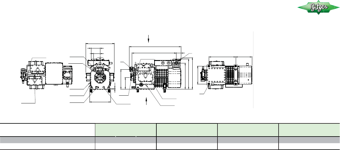
DIMENSIONAL DRAWINGS
2KES-05Y .. 2FES-3Y
68
J
K
74
105
106
202
VIEW A
G
F
'/6/
/3
137)
+3
137)
VIEW B
D1 D
E
9
A
B
H
C
A
,7(0DQG
81)
,7(0
B
L
,7(0
0[
Connection positions
1 High pressure connection (HP)
2 Discharge gas temp. sensor (HP)
or CIC sensor
3 Low pressure connection (LP)
4 CIC System: spray nozzle (LP)
5 Oil fi ll plug
6 Oil drain
7 Oil fi lter (magnetic screw)
8 Oil return (oil separator)
9a Gas equalisation (parallel operation)
9b Oil equalisation (parallel operation)
10 Crankcase heater
11 Oil pressure connection +
12 Oil pressure connection -
16 Connection for oil monitoring
(oil sensor or differential oil pressure
switch “Delta-P”)
21 Connection for oil service valve
A B C D D1 E F G H J K L
mm mm mm mm mm mm mm mm mm mm mm mm
2KES-05Y, 2JES-07Y, 2HES-1Y, 2HES-2Y
343 220 273 208 65 162 148 37 242 247 32 232
2GES-2Y, 2FES-2Y, 2FES-3Y
10

2EES-2Y .. 2CES-4Y
Displacement at
1450 min
-1
(m
3
/h)
BITZER
BITZER
Former Models
Dorin Bock Frascold Copeland China Copeland DWM
11.40 2EES-2Y 2EC-2.2 H280CC HG22e/125-4 D2-11.1Y --
2EES-3Y 2EC-3.2 HG22e/125-4 S
13.40 2DES-2Y 2DC-2.2 - HG22e/160-4
D2-13.1Y LA20-0200 DLF-201
2DES-3Y 2DC-3.2 HG22e/160-4 S D3-13.1Y LA20-020E DLF-20X
LA20-0300 DLF-301
LA20-030E DLF-30X
DLJ-201
DLJ-20X
DLJ-301
DLJ-30X
16.20 2CES-3Y 2CC-3.2 H300CC HG22e/190-4 D2-15.1Y - D2DC-500
2CES-4Y 2CC-4.2 H350CC HG22e/190-4 S D3-15.1Y D2DC-50X
D3-16.1Y
D4-16.1Y
BITZER COMPRESSOR COMPARISON
11

TECHNICAL DATA
2EES-2Y .. 2CES-4Y
Pipe connections Electrical data
Compressor
type
Motor
version
Displacement
at 1450 min
-1
Number of
cylinders
Oil
charge Weight
DL
Discharge
line
SL
Suction
line
CR
- Steps -
Motor
connection
Max.
Operating
current
Max.
Power
consumption
(m³/h) dm³ kg mm inch mm inch %
①
Volt
②
Amp.
③
kW
③
2EES-2Y 2
11.4 2 1.5
68
16 ⅝ 22 ⅞
-
/ Y
10.4/6.0 3.3
2EES-3Y 1 71 13.4/7.5 3.8
2DES-2Y 2
13.4 2 1.5
68
16 ⅝ 22 ⅞
220..240∆/ 13.4/7.5 4.0
2DES-3Y 1 71
380..420Y/3/50 15.0/8.6 4.6
2CES-3Y 2
16.2 2 1.5
70
16 ⅝ 22 ⅞
265..290∆/ 15.8/9.1 5.0
2CES-4Y 1 70 440..480Y/3/60 17.4/10.0 5.6
12

DIMENSIONAL DRAWINGS
Connection positions
1 High pressure connection (HP)
2 Discharge gas temp. sensor (HP)
or CIC sensor
3 Low pressure connection (LP)
4 CIC System: spray nozzle (LP)
5 Oil fi ll plug
6 Oil drain
7 Oil fi lter (magnetic screw)
8 Oil return (oil separator)
9a Gas equalisation (parallel operation)
9b Oil equalisation (parallel operation)
10 Crankcase heater
11 Oil pressure connection +
12 Oil pressure connection -
16 Connection for oil monitoring
(oil sensor or differential oil pressure
switch “Delta-P”)
21 Connection for oil service valve
2EES-2Y .. 2CES-4Y
A B C D D1 E F G H J K L
mm mm mm mm mm mm mm mm mm mm mm mm
2EES-2Y, 2EES-3Y, 2DES-2Y, 2DES-3Y
398 259 307 223 85 198 167 42 266 275 37 262
2CES-3Y, 2CES-4Y
13
81
123
L
90
121
VIEW B
E
D D1
13
VIEW A
J K
G
B
A
C
H
F
A
6/
,7(0DQG
81)
B
241
,7(0
/3
137)
'/
+3
137)
,7(0
0[

Displacement at
1450 min
-1
(m
3
/h)
BITZER
BITZER
Former Models
Dorin Bock Frascold Copeland China Copeland DWM
18.10
4FES-3Y 4FC-3.2 H380CC
HG34e/215-4
D3-18.1Y LA40-0300 DLL-301
4FES-5Y 4FC-5.2 H403CC
HG34e/215-4 S
D4-18.1Y LA40-030E DLL-30X
D3-19.1Y LA40-0400 DLL-401
D4-19.1Y LA40-040E DLL-40X
Q4-20.1E D2DD-500
Q4-20.1Y D2DD-50X
22.70
4EES-4Y 4EC-4.2 H503CC
HG34e/255-4
Q4-21.1Y LA50-0400 D2SA-450 Air
4EES-6Y 4EC-6.2 H551CC
HG34e/255-4 S
Q5-21.1Y LA50-040E D2SA-45X Air
Q4-24.1E D2SA-450
Q4-24.1Y D2SA-45X
Q5-24.1Y D2SA-550
D2SA-55X
DLSG-401
DLSG-40X
D2DL-400 DC
D2DL-40X
D2DL-750
D2DL-75X
14
BITZER COMPRESSOR COMPARISON
4FES-2Y .. 4EES-6Y

Displacement at
1450 min
-1
(m
3
/h)
BITZER
BITZER
Former Models
Dorin Bock Frascold Copeland China Copeland DWM
26.80 4DES-5Y 4DC-5.2 H551CS HG34e/315-4 Q4-25.1Y 2SCW-0550 D2SC-550 Air
4DES-7Y 4DC-7.2 H701CC HG34e/315-4 S Q5-25.1Y 2SCW-055E D2SC-55X Air
Q7-25.1Y D2SC-550
Q5-28.1E D2SC-55X
Q5-28.1Y D2SC-650
Q7-28.1Y D2SC-65X
D2DB-500 DC
D2DB-50X
D2DB-750
D2DB-75X
32.50 4CES-6Y 4CC-6.2 H701CS HG34e/380-4 Q5-33.1E 2SKW-0750 D2SK-650
4CES-9Y 4CC-9.2 H751CC HG34e/380-4 S Q5-33.1Y 2SKW-075E D2SK-65X
Q7-33.1Y D3SA-750
S5-33Y D3SA-75X
S7-33Y D3DA-500 DC
D3DA-50X
D3DA-750
D3DA-75X
15
BITZER COMPRESSOR COMPARISON
4DES-5Y .. 4CES-9Y

TECHNICAL DATA
Pipe connections Electrical data
Compressor
type
Motor
version
Displacement
at 1450 min
-1
Number
of
cylinders
Oil
charge Weight
DL
Discharge
line
SL
Suction
line
CR
- Steps -
Motor
connection
Max.
Operating
current
Max.
Power
consumption
(m³/h) dm³ kg mm inch mm inch %
①
Volt
②
Amp.
③
kW
③
4FES-3Y 2
18.1 4 2.0
82
16 ⅝ 22 ⅞
50
/ Y 16.5/9.5 5.3
4FES-5Y 1 86 18.8/10.8 5.8
4EES-4Y 2
22.7 4 2.0
84
16 ⅝ 28 1⅛
21.2/12.2 6.9
4EES-6Y 1 86 220..240∆/ 23.7/13.6 7.6
4DES-5Y 2
26.8 4 2.0
86
22 ⅞ 28 1⅛
380..420Y/3/50 25.2/14.5 8.1
4DES-7Y 1 89 265..290∆/ 28.7/16.5 8.9
4CES-6Y 2
32.5 4 2.0
91
22 ⅞ 28 1⅛
440..480Y/3/60 30.8/17.7 9.7
4CES-9Y 1
91
35.1/20.2 11.3
16
4FES-3Y .. 4CES-9Y

DIMENSIONAL DRAWINGS
Connection positions
1 High pressure connection (HP)
2 Discharge gas temp. sensor (HP)
or CIC sensor
3 Low pressure connection (LP)
4 CIC System: spray nozzle (LP)
5 Oil fi ll plug
6 Oil drain
7 Oil fi lter (magnetic screw)
8 Oil return (oil separator)
9a Gas equalisation (parallel operation)
9b Oil equalisation (parallel operation)
10 Crankcase heater
11 Oil pressure connection +
12 Oil pressure connection -
16 Connection for oil monitoring
(oil sensor or differential oil pressure
switch “Delta-P”)
21 Connection for oil service valve
4FES-3Y .. 4CES-9Y
A B C D D1 E F G H J K L
mm mm mm mm mm mm mm mm mm mm mm mm
4FES-3Y, 4FES-5Y 432 309 347 293 75 198 221 42 313 361 37 306
4EES-4Y, 4EES-6Y 432 309 352 293 75 198 221 56 316 361 37 306
4DES-5Y 432 309 352 293 75 198 221 56 316 361 42 310
4DES-7Y, 4CES-6Y, 4CES-9Y 457 309 352 293 101 198 246 56 316 386 42 310
17
125
'/ 6/
,7(0DQG
81)
B
A
H
C
F
L
A
J
VIEW B
D1 D
E
13
VIEW A
137)
0[
+3
,7(0 ,7(0
12
B
241
G
K
/3
137)

Displacement at
1450 min
-1
(m
3
/h)
BITZER
BITZER
Former Models
Dorin Bock Frascold Copeland China Copeland DWM
34.70 4VES-6Y ---Q5-36.1Y -
-
4VES-7Y
4VCS-6.2 Q7-36.1Y
4VES-10Y 4VCS-10.2
41.30 4TES-8Y - H751CS HG4/465-4 S8-42E 3SC1-1000 D3SC-750
4TES-9Y 4TCS-8.2 H851CS HG4/465-4 S S8-42Y
3SC1-100E
D3SC-75X
4TES-12Y 4TCS-12.2 H1001CC S12-42Y D3SC-1000
D3SC-100X
D3DC-1000
D3DC-100X
D3DC-750 DC
D3DC-75X
18
BITZER COMPRESSOR COMPARISON
4VES-6Y .. 4TES-12Y

Displacement at
1450 min
-1
(m
3
/h)
BITZER
BITZER
Former Models
Dorin Bock Frascold Copeland China Copeland DWM
48.50 4PES-10Y - H1001CS HG4/555-4 S10-52E 3SS1-1500 D3DS-1000 DC
4PES-12Y 4PCS-10.2 H1501CC HG4/555-4 S S10-52Y
3SS1-150E
D3DS-100X
4PES-15Y 4PCS-15.2 S15-52Y D3DS-1500
D3DS-150X
D3SS-1000
D3SS-100X
D3SS-1500
D3SS-150X
56.20 4NES-12Y - H1501CS HG4/650-4 S12-56E 4SAH-2000 D4SA-1000
4NES-14Y 4NCS-12.2 H2001CC HG4/650-4 S S15-56Y
4SAH-200E
D4SA-100X
4NES-20Y 4NCS-20.2 S20.56Y D4SA-2000
V15-59E D4SA-200X
V15-59Y D4SF-1000
V20-59Y D4SF-100X
D4DA-100X
D4DA-2000
D4DA-200X
D4DF-1000 DC
D4DF-100X
19
BITZER COMPRESSOR COMPARISON
4PES-10Y .. 4NES-20Y

TECHNICAL DATA
Pipe connections Electrical data
Compressor
type
Motor
version
Displacement
at 1450 min
-1
Number
of
cylinders
Oil
charge Weight
DL
Discharge
line
SL
Suction
line
CR
- Steps -
Motor
connection
Max.
Operating
current
Max.
Power
consumption
(m³/h) dm³ kg mm inch mm inch %
①
Volt
②
Amp.
③
kW
③
4VES-6Y 3
34.7 4 2.6
129
22 ⅞ 28 1⅛
50
9.4 6
4VES-7Y
2
129 PW
④
16.6 11
4VES-10Y 1 139 19.9 12
4TES-8Y
3
41.3 4 2.6
134
28 1⅛ 35 1⅜
11.4 7
4TES-9Y 2 134 19.9 13
4TES-12Y 1 141 380..420YY/3/50 25.1 14
4PES-10Y 3
48.5 4 2.6
139
28 1⅛
35 1⅜ 440..480YY/3/60 12.9 8
4PES-12Y 2 139 35 1⅜ 22.7 14
4PES-15Y 1 147 42 1⅝ 28.2 16
4NES-12Y 3
56.2 4 2.6
141
28 1⅛
35 1⅜ 14.9 9
4NES-14Y 2 141 35 1⅜ 26.6 17
4NES-20Y 1 150 42
1⅝
33.2 19
20
4VES-6Y .. 4NES-20Y

DIMENSIONAL DRAWINGS
Connection positions
1 High pressure connection (HP)
2 Discharge gas temp. sensor (HP)
or CIC sensor
3 Low pressure connection (LP)
4 CIC System: spray nozzle (LP)
5 Oil fi ll plug
6 Oil drain
7 Oil fi lter (magnetic screw)
8 Oil return (oil separator)
9a Gas equalisation (parallel operation)
9b Oil equalisation (parallel operation)
10 Crankcase heater
11 Oil pressure connection +
12 Oil pressure connection -
16 Connection for oil monitoring
(oil sensor or differential oil pressure
switch “Delta-P”)
21 Connection for oil service valve
A B C D D1 E F G H J K L
mm mm mm mm mm mm mm mm mm mm mm mm
4VES-6Y, 4VES-7Y, 4VES-10Y 633 303 385 367 140 256 44 61 161 558 42 338
4TES-8Y, 4TES-9Y, 4TES-12Y 633 303 385 367 140 256 44 64 161 557 56 342
4PES-10Y, 4PES-12Y 633 303 385 367 140 256 44 64 161 557 56 342
4PES-15Y 658 303 385 367 162 256 48 110 173 582 56 342
4NES-12Y, 4NES-14Y 633 303 385 367 140 256 44 64 161 557 56 342
4NES-20Y 658 303 385 367 162 256 48 110 173 582 56 342
21
4VES-6Y .. 4NES-20Y
L
F
19
B
152
A
B
H
C
K
A
J
G
'/
,7(0DQG
137)
,7(0
137)
6/
300
5
142
,7(0
0[
,7(0
12
,7(0
0[
+3
137)
+3
137)
VIEW A
/3
81)
,7(0
137)
VIEW B
D D1
E
21

Displacement at
1450 min
-1
(m
3
/h)
BITZER
BITZER
Former Models
Dorin Bock Frascold Copeland China Copeland DWM
63.50 4JE-13Y - H1601CS HG5/725-4
---
4JE-15Y 4J-13.2 H2201CC HG5/725-4 S
4JE-22Y
4J-22.2
73.70 4HE-15Y - H2000CS HG5/830-4 V15-71E 4SLW-1500 D4SH-1500
4HE-18Y 4H-15.2 H2500CC HG5/830-4 S V15-71Y 4SLW-150E D4SH-150X
4HE-25Y 4H-25.2 V25-71Y 4SHH-2500 D4SH-2500
4SHH-250E
D4SH-250X
D4SL-1500
D4SL-150X
D4DH-150X
D4DH-2500
D4DH-250X
D4DL-1500 DC
D4DL-150X
22
BITZER COMPRESSOR COMPARISON
4JE-13Y .. 4HE-25Y

Displacement at
1450 min
-1
(m
3
/h)
BITZER
BITZER
Former Models
Dorin Bock Frascold Copeland China Copeland DWM
84.60 4GE-20Y - H2500CS HG5/945-4 V20-84E 4STW-2000 D6SA-3000
4GE-23Y 4G-20.2 H3000CC HG5/945-4 S V20-84Y
4STW-200E
D6SA-300X
4GE-30Y 4G-30.2 V30-84Y 4SJH-3000 D6SF-2000
4SJH-300E
D6SF-200X
D4SJ-2000
D4SJ-200X
D4SJ-3000
D4SJ-300X
D4ST-2000
D4ST-200X
D4DJ-200X
D4DJ-3000
D4DJ-300X
D4DT-2200 DC
D4DT-220X
23
BITZER COMPRESSOR COMPARISON
4GE-20Y .. 4GE-30Y

Displacement at
1450 min
-1
(m
3
/h)
BITZER
BITZER
Former Models
Dorin Bock Frascold Copeland China Copeland DWM
101.80 4FE-25Y - - - V25-103E 6SLW-2500 D6SH-2000
4FE-28Y V25-103Y 6SLW-250E D6SH-200X
4FE-35Y V35-103Y 6SHH-3500 D6SH-3500
Z25-106E
6SHH-350E D6SH-350X
Z25-106Y D6SL-2500
Z35-106Y D6SL-250X
D6DH-200X
D6DH-3500
D6DH-350X
D6DL-2700 DC
D6DL-270X
24
BITZER COMPRESSOR COMPARISON
4FE-25Y .. 4FE-35Y

TECHNICAL DATA
Pipe connections Electrical data
Compressor
type
Motor
version
Displacement
at 1450 min
-1
Number
of
cylinders
Oil
charge Weight
DL
Discharge
line
SL
Suction
line
CR
- Steps -
Motor
connection
Max.
Operating
current
Max.
Power
consumption
(m³/h) dm³ kg mm inch mm inch %
①
Volt
②
Amp.
③
kW
③
4JE-13Y 3
63.5 4 4.0
179
28 1⅛ 42 1⅝
18.8 11
4JE-15Y 2 190 30.8 19
4JE-22Y 1 190 37.2 21
4HE-15Y 3
73.7 4 4.0
183
28 1⅛
42 1⅝
PW 21.4 13
4HE-18Y 2 190 42 1⅝ 36.7 22
4HE-25Y 1 194 54 2⅛ 50 380..420YY/3/50 44 25
4GE-20Y 3
84.6 4 4.5
192
28 1⅛ 54 2⅛
440..480YY/3/60 24.6 16
4GE-23Y 2 192 43.9 27
4GE-30Y 1 206 51.2 28
4FE-25Y 3
101.8 4 4.5
196
28 1⅛ 54 2⅛
30.5 19
4FE-28Y 2 207 52.8 31
4FE-35Y 1 207 62.1 35
25
4JE-13Y .. 4FE-35Y

DIMENSIONAL DRAWINGS
Connection positions
1 High pressure connection (HP)
2 Discharge gas temp. sensor (HP)
or CIC sensor
3 Low pressure connection (LP)
4 CIC System: spray nozzle (LP)
5 Oil fi ll plug
6 Oil drain
7 Oil fi lter (magnetic screw)
8 Oil return (oil separator)
9a Gas equalisation (parallel operation)
9b Oil equalisation (parallel operation)
10 Crankcase heater
11 Oil pressure connection +
12 Oil pressure connection -
16 Connection for oil monitoring
(oil sensor or differential oil pressure
switch “Delta-P”)
21 Connection for oil service valve
26
B
C
VIEW B
D
E
D1
21
VIEW A
+3
137)
/3
137)
,7(0
137)
12
360
G
,7(0
137)
,7(0
81)
,7(0E
137)
,7(0D
137)
,7(0
81)
,7(0DQG
0[
+3
137)
A
B
A
J
F
H
L
K
157
6/
,7(0
137)
,7(0
137)
'/
,7(0
0[
4JE-13Y .. 4FE-35Y

DIMENSIONAL DRAWINGS
A B C D D1 E F G H J K L
mm mm mm mm mm mm mm mm mm mm mm mm
4JE-13Y, 4JE-15Y 688 456 452 381 151 305 66 110 361 501 56 362
4JE-22Y 688 456 452 381 151 305 66 110 361 501 56 362
4HE-15Y, 4HE-18Y
688 456 452 381 151 305 66 110 361 501 56 362
4HE-25Y
737 456 452 381 200 305 87 127 377 549 56 362
4GE-20Y, 4GE-23Y 706 456 452 381 169 305 76 127 377 519 56 362
4GE-30Y
737 456 452 381 200 305 87 127 377 549 56 362
4FE-25Y, 4FE-28Y
737 456 452 381 200 305 87 127 377 549 56 362
4FE-35Y 737 456 452 381 200 305 87 127 377 549 56 362
27
4JE-13Y .. 4FE-35Y

BITZER COMPRESSOR COMPARISON
Displacement at
1450 min
-1
(m
3
/h)
BITZER
BITZER
Former Models
Dorin Bock Frascold Copeland China Copeland DWM
95.30 6JE-22Y -
-
HG6/1080-4 V25-93Y
--
6JE-25Y 6J-22.2 HG6/1080-4 S V32-93Y
6JE-33Y 6J-33.2
110.50 6HE-25Y - H3000CS HG6/1240-4 -
--
6HE-28Y 6H-25.2 H3500CC HG6/1240-4 S
6HE-35Y
6H-35.2
126.80 6GE-30Y -i H3500CS HG6/1410-4 Z30-126E 6STW-3200 D6SJ-3000
6GE-34Y 6G-30.2 H4000CC HG6/1410-4 S Z30-126Y 6STW-320E D6SJ-300X
6GE-40Y 6G-40.2 Z40-126Y
6SJH-4000
D6SJ-4000
6SJH-400E
D6SJ-400X
D6ST-3200
D6ST-320X
D6DJ-300X
D6DJ-4000
D6DJ-400X
D6DT-3200 DC
D6DT-300X
28
6JE-22Y .. 6GE-40Y

TECHNICAL DATA
Pipe connections Electrical data
Compressor
type
Motor
version
Displacement
at 1450 min
-1
Number
of
cylinders
Oil
charge Weight
DL
Discharge
line
SL
Suction
line
CR
- Steps -
Motor
connection
Max.
Operating
current
Max.
Power
consumption
(m³/h) dm³ kg mm inch mm inch %
①
Volt
②
Amp.
③
kW
③
6JE-22Y 3
95.3 6 4.75
213
35 1⅜ 54 2⅛
26.6 16
6JE-25Y 2 228 46.4 27
6JE-33Y 1 231 53.2 30
6HE-25Y 3
110.5 6 4.75
224
35 1⅜ 54 2⅛
380..420YY/3/50 31.3 19
6HE-28Y 2 228 66 53.2 33
6HE-35Y 1 235 altern. 440..480YY/3/60 64.4 36
6GE-30Y 3
126.8 6 4.75
228
35 1⅜ 54 2⅛
33 38 23
6GE-34Y 2 228 PW
④
65.5 40
6GE-40Y 1 238 73.9 42
29
6JE-22Y .. 6GE-40Y

DIMENSIONAL DRAWINGS
Connection positions
1 High pressure connection (HP)
2 Discharge gas temp. sensor (HP)
or CIC sensor
3 Low pressure connection (LP)
4 CIC System: spray nozzle (LP)
5 Oil fi ll plug
6 Oil drain
7 Oil fi lter (magnetic screw)
8 Oil return (oil separator)
9a Gas equalisation (parallel operation)
9b Oil equalisation (parallel operation)
10 Crankcase heater
11 Oil pressure connection +
12 Oil pressure connection -
16 Connection for oil monitoring
(oil sensor or differential oil pressure
switch “Delta-P”)
21 Connection for oil service valve
30
B
C
,7(0
,7(0DQG
137)
,7(0
137)
,7(0
,7(0E
81)
137)
0[
137)
,7(0D
,7(0
81)
70 K G
12
360
0[
,7(0
137)
,7(0
'/
137)
,7(0
6/
A
B
L
J
H
F
158
A
137)
+3
,7(0
VIEW A
137)
+3
137)
/3
137)
VIEW B
D
D1
E
21
6JE-22Y .. 6GE-40Y

DIMENSIONAL DRAWINGS
A B C D D1 E F G H J K L
mm mm mm mm mm mm mm mm mm mm mm mm
6JE-22Y, 6JE-25Y 766 503 447 381 211 305 76 127 377 740 64 271
6JE-33Y 797 503 447 381 242 305 87 127 377 771 64 271
6HE-25Y, 6HE-28Y 766 503 447 381 211 305 76 127 377 740 64 271
6HE-35Y 797 503 447 381 242 305 87 127 377 771 64 271
6GE-30Y, 6GE-34Y 766 503 447 381 211 305 76 127 377 740 64 271
6GE-40Y 797 503 447 381 242 305 87 127 377 771 64 271
31
6JE-22Y .. 6GE-40Y

BITZER COMPRESSOR COMPARISON
Displacement at
1450 min
-1
(m
3
/h)
BITZER
BITZER
Former Models
Dorin Bock Frascold Copeland China Copeland DWM
151.60 6FE-40Y - H4500CS HG7/1620-4 W40-142Y 6SUW-4000 D8DH-400X
6FE-44Y 6F-40.2 H5000CC HG7/1620-4 S Z40-154E 6SUW-400E D8DH-5000
6FE-50Y 6F-50.2 HG7/1860-4 Z40-154Y 6SKH-5000 D8DH-500X
HG7/1860-4 S Z50-154Y 6SKH-500E D8DL-370X
D8SH-400X
D6SU-400X
D6SK-400X
D6SK-5000
D6SK-500X
32
6FE-40Y .. 6FE-50Y

TECHNICAL DATA
Pipe connections Electrical data
Compressor
type
Motor
version
Displacement
at 1450 min
-1
Number
of
cylinders
Oil
charge Weight
DL
Discharge
line
SL
Suction
line
CR
- Steps -
Motor
connection
Max.
Operating
current
Max.
Power
consumption
(m³/h) dm³ kg mm inch mm inch %
①
Volt
②
Amp.
③
kW
③
6FE-40Y 3
151.6 6 4.75
238
42 1⅝ 54 2⅛
66
altern.
33
380..420YY/3/50
440..480YY/3/60
PW
④
48.5 27
6FE-44Y 2 241 380..400YY/3/50 83.2 46
6FE-50Y 1 241 440..460YY/3/60 96.2 51
33
6FE-40Y .. 6FE-50Y

DIMENSIONAL DRAWINGS
Connection positions
1 High pressure connection (HP)
2 Discharge gas temp. sensor (HP)
or CIC sensor
3 Low pressure connection (LP)
4 CIC System: spray nozzle (LP)
5 Oil fi ll plug
6 Oil drain
7 Oil fi lter (magnetic screw)
8 Oil return (oil separator)
9a Gas equalisation (parallel operation)
9b Oil equalisation (parallel operation)
10 Crankcase heater
11 Oil pressure connection +
12 Oil pressure connection -
16 Connection for oil monitoring
(oil sensor or differential oil pressure
switch “Delta-P”)
21 Connection for oil service valve
A B C D D1 E F G H J K L
mm mm mm mm mm mm mm mm mm mm mm mm
6FE-40Y, 6FE-44Y 790 503 447 381 242 305 87 127 377 729 111 381
6FE-50Y
790 503 447 381 242 305 87 127 377 729 111 381
34
C
D1
B
VIEW B
E
D
21
VIEW A
+3
137)
/3
137)
+3
137)
,7(0
137)
K
360
G
12
,7(0
137)
,7(0DQG
0[
,7(0
81)
,7(0
137(
,7(0D
137(
,7(0E
137(
,7(0
81)
A
B
F
J
158
A
L
H
6/
,7(0
0[
,7(0
137)
'/
,7(0
137)
6FE-40Y .. 6FE-50Y

BITZER COMPRESSOR COMPARISON
35
Displacement at
1450 min
-1
(m
3
/h)
BITZER
BITZER
Former Models
Dorin Bock Frascold Copeland China Copeland DWM
185.00 8GE-60Y 8CG-60.2 H6000CC HG7/2110-4 W40-168Y
-
D8SJ-4500
HG7/2110-4 S W50-168Y D8SJ-450X
W50-187Y D8SJ-500X
W60-187Y D8SJ-6000
D8SJ-600X
D8DJ-500X
D8DJ-6000
D8DJ-600X
D8DT-450X
221.00 8FE-70Y 8FC-70.2
-
HG8/2470-4 W60-206Y
-
D8SK-600X
HG8/2470-4 S W70-206Y D8SK-7000
HG8/2830-4
W70-228Y
D8SK-700X
HG8/2830-4 S
W75-228Y
W75-240Y
W80-240Y
8GE-60Y .. 8FE-70Y

TECHNICAL DATA
36
Pipe connections Electrical data
Compressor
type
Motor
version
Displacement
at 1450 min
-1
Number
of
cylinders
Oil
charge Weight
DL
Discharge
line
SL
Suction line
CR
- Steps -
Motor
connection
Max.
Operating
current
Max.
Power
consumption
(m³/h) dm³ kg mm inch mm inch %
①
Volt
②
Amp.
③
kW
③
8GE-60(Y) 1
185 8 5.0
350
42 1⅝ 76 3⅛ 75 PW
④
113 63
altern.
380..420Y/3/50
8FE-70(Y) 1
221 8 5.0
374
54 2⅛ 76 3⅛ 50
440..480Y/3/60 139 78
8GE-60Y .. 8FE-70Y
DIMENSIONAL DRAWINGS
Connection positions
1 High pressure connection (HP)
2 Discharge gas temp. sensor (HP)
or CIC sensor
3 Low pressure connection (LP)
4 CIC System: spray nozzle (LP)
5 Oil fi ll plug
6 Oil drain
7 Oil fi lter (magnetic screw)
8 Oil return (oil separator)
9a Gas equalisation (parallel operation)
9b Oil equalisation (parallel operation)
10 Crankcase heater
11 Oil pressure connection +
12 Oil pressure connection -
16 Connection for oil monitoring
(oil sensor or differential oil pressure
switch “Delta-P”)
21 Connection for oil service valve
37
A B C D D1 E F G H J K L
mm mm mm mm mm mm mm mm mm mm mm mm
8GE-60Y 886 485 538 457 281 305 82 158 445 757 110 336
8FE-70Y 902 485 538 457 281 305 82 158 444 764 129 336
8GE-60Y .. 8FE-70Y
198
G
360
B
12
K
,7(0DQG
0[
,7(0
137)
,7(0
81)
,7(0
81)
,7(0
137)
,7(0
137)
A
B
A
C
L
H
J F
515
+3
137)
,7(0E
137)
,7(0D
137)
'/
6/
,7(0
0;
VIEW A
/3
137)
+3
137)
VIEW B
D1 D
E

TECHNICAL DATA EXPLANATIONS
CR Capacity control (option)
220..240 V/1/50/60 Hz
Tolerance (±10%) based on mean value of voltage range. Other voltages and electrical supplies upon request.
Data refer to 400 V/3/50 Hz at direct mains operation. For the selection of contactors, cables and fuses the max. operating current / max. power consumption must be
considered. See also
Contractors: Operational category AC3. Use thermal overload relay to limit max operating current.
PW: motor for Part Winding start Y/YY
• 4VES-6Y .. 6FE-50Y winding partition 50%/50%
• 8GE-50Y .. 8FE-70Y
/∆∆ winding partition 60%/40%
• For Part Winding start select motor contactors for approx. 60% of the max. operating current. Y/
∆ version upon request
Data for frequency inverter (FI) selection
- motor version 3 (R134a compressors):
based on 400 V/3/50 Hz supply voltage and use of 400 V/3/50 Hz standard motor for FI operation up to 70 Hz.
FI with motor version 1 and 2:
operation in the entire application range above 50 Hz requires motor with special voltage.
Selection upon request.
38

NOTES
39

BITZER Australia Pty Limited
Head Office
134 Dunheved Circuit,
St Marys, NSW 2760
Australia
tel +61 (2) 8801 9300
fax +61 (2) 9673 4698
www.bitzer.com.au
