
Advanced
Lightband
User’s Manual | 2003336C
Do not operate the Advanced Lightband (ALB) before reading this document. Do not operate the ALB beyond the
operating limits.
The ALB does not involve any high-energy liquid, solid fuels, or any material with inherently hazardous physical or
chemical properties.
spacesystems@rocketlabusa.com
rocketlabusa.com

2003336C Advanced Lightband User's Manual PSC by Rocket Lab
February 2023 https://www.rocketlabusa.com/space-systems/separation-systems/ Page 2 of 41
Table of Contents
1. REVISION HISTORY ................................................................................................................................................................................ 3
2. INTRODUCTION ....................................................................................................................................................................................... 4
3. PARAMETERS ......................................................................................................................................................................................... 6
4. ALB DESCRIPTION .................................................................................................................................................................................. 7
4.1 PART MARKING ....................................................................................................................................................................................... 7
4.2 TOLERANCE ON DIMENSIONS ................................................................................................................................................................... 7
4.3 MECHANICAL DESCRIPTION AND INTERFACE ............................................................................................................................................. 7
4.4 ELECTRICAL INTERFACE ........................................................................................................................................................................ 10
4.5 ACCESSIBILITY AND STAY-OUT ZONES .................................................................................................................................................... 11
4.6 MATERIALS AND SURFACE TREATMENTS................................................................................................................................................. 12
4.7 STIFFNESS ........................................................................................................................................................................................... 12
4.8 STIFFNESS OF ADJOINING STRUCTURES ................................................................................................................................................. 13
4.9 LINE LOAD LIMITS ................................................................................................................................................................................. 16
4.10 FATIGUE LIMITS & MASS-LOADED VIBRATION...................................................................................................................................... 17
4.11 FLATNESS AND PARALLELISM ............................................................................................................................................................ 18
4.12 SOFTRIDE AND ALB ......................................................................................................................................................................... 20
4.13 LIFECYCLE ....................................................................................................................................................................................... 20
4.14 ROTATION RATES ............................................................................................................................................................................. 21
4.15 SEPARATION VELOCITY AND SEPARATION SPRINGS ............................................................................................................................ 22
5. VERTICAL AND HORIZONTAL INTEGRATION TO ADJOINING VEHICLES ........................................................................................ 24
6. RELIABILITY, FAILURE MODES AND ANOMALY REPORTING .......................................................................................................... 26
6.1 FAILURE MODES, EFFECTS AND PREVENTATIVE ACTIONS ........................................................................................................................ 26
7. TESTING ................................................................................................................................................................................................. 27
7.1 TEST SUMMARY .................................................................................................................................................................................... 27
7.2 BUILD VERIFICATION ............................................................................................................................................................................. 27
7.3 COMPONENT RANDOM VIBRATION .......................................................................................................................................................... 28
7.4 THERMAL VACUUM ................................................................................................................................................................................ 28
7.5 SHOCK (CUSTOM TEST) ........................................................................................................................................................................ 29
7.6 SEPARATION TESTING (CUSTOM TEST) ................................................................................................................................................... 29
7.7 STRENGTH (CUSTOM TEST) ................................................................................................................................................................... 30
7.8 FATIGUE (CUSTOM TEST) ...................................................................................................................................................................... 30
8. SPECIFYING AN ALB ............................................................................................................................................................................ 31
8.1 DETERMINE STIFFNESS REQUIREMENTS .................................................................................................................................................. 31
8.2 DETERMINE STRENGTH REQUIREMENTS .................................................................................................................................................. 31
8.3 SELECT ALB BOLT CIRCLE DIAMETER..................................................................................................................................................... 31
8.4 COMPLETE VIRTUAL FIT CHECK AND PLAN LOGISTICS................................................................................................................................ 31
8.5 SEPARATION SWITCH QUANTITY (SW) .................................................................................................................................................... 31
8.6 SEPARATION CONNECTOR QUANTITY (SC) .............................................................................................................................................. 31
8.7 END USE (FLT OR EDU) ....................................................................................................................................................................... 31
8.8 SEPARATION SPRINGS........................................................................................................................................................................... 31
8.9 SPECIFYING ALB .................................................................................................................................................................................. 31
9. PURCHASING, DELIVERABLES, & SCHEDULE .................................................................................................................................. 32
9.1 PURCHASING AN ALB ............................................................................................................................................................................ 32
9.2 STANDARD DELIVERY SCHEDULE ........................................................................................................................................................... 32
9.3 ALB DELIVERABLES .............................................................................................................................................................................. 32
9.4 ALB STEP FILES .................................................................................................................................................................................. 32
9.5 ALB FINITE ELEMENT MODELS .............................................................................................................................................................. 32
9.6 CUSTOM UNITS ..................................................................................................................................................................................... 32
9.7 ACCESSORIES ...................................................................................................................................................................................... 32
9.7.1 Separation Connectors ............................................................................................................................................................... 32
9.7.2 Separation Switches ................................................................................................................................................................... 33
9.7.3 Separation Springs ..................................................................................................................................................................... 33
10. MANUFACTURING PROCESS .......................................................................................................................................................... 33
11. ALB TESTING AND PROCEDURES PERFORMED BY CUSTOMER ............................................................................................... 33
12. GROUND SUPPORT EQUIPMENT (GSE) ......................................................................................................................................... 34
13. WARRANTY AND GLOSSARY .......................................................................................................................................................... 36
13.1 WARRANTY ...................................................................................................................................................................................... 36
13.2 GLOSSARY ....................................................................................................................................................................................... 36
14. APPENDIX A: ALB ACCESSORIES .................................................................................................................................................. 37
14.1.1 ALB Separation Connector ......................................................................................................................................................... 37
14.1.2 ALB Separation Switch ............................................................................................................................................................... 38
14.1.3 Separation Springs ..................................................................................................................................................................... 38
14.1.4 Wiring Separation Switch and Separation Connector ................................................................................................................. 39

2003336C Advanced Lightband User's Manual PSC by Rocket Lab
February 2023 https://www.rocketlabusa.com/space-systems/separation-systems/ Page 3 of 41
1. Revision History
Rev. Issued
Written
By
Released
By
Change Description
- & A
See previous revisions
B
07Jun22
ML
CF
• Updated cover page with updated logo and graphic
• Typo fixes and grammatical changes throughout document
• Table 3-1: updated dim E stay out zone and latch up distance range, updated wording and
symbol Fws for clarity.
• Were Figure 4-25, 4-26 clarified stow screw torque at ‘ping’ for ALB24, increased first peak
torque to 22 in lb
• Section 8.2: added details PSC will request from customer to ensure strength requirement
compliance
• Section 8.8: reduced maximum number of springs for standard ALB to n/4
• Section 9.1: updated payment milestones
• Section 9.2: updated standard lead time
• Figure 9-1: updated number of springs for custom Lightband
• Was Section 14: updated checklist typos
• Table 14-3: updated wording and symbol Fws for clarity.
C
24Feb23
MH/Nirja
Dave
CMF
• Relocated Revision History to Section 1
• Removed Operation and Integration Section from procedure and creating two new documents
(PSC-RL document 3000355 ALB Operating Procedure and PSC-RL document 3000349 ALB
Pack-Unpack Procedure)
• Updated PSC references to PSC-RL
• Updated Section 2, features and benefits
• Updated references from Table 2-1 to Table 3-1
• Table 3-1Added row for default quantity for separation springs and updated storage
• Section 4.9: Additional line loading guidance
• Added Section 4.10 Fatigue Limits & Mass-Loaded Vibration
• Updated Section 4.13 Lifecycle
• Section 8.8: Updated language to reflect certain ALB sizes have default spring quantity of 4
• Section 9.6: Updated language to reflect certain ALB sizes have default spring quantity of 4
• Updated Section 13.1 Warranty
• Section 14: Updated attachment references to PSC-RL document 3000355

2003336C Advanced Lightband User's Manual PSC by Rocket Lab
February 2023 https://www.rocketlabusa.com/space-systems/separation-systems/ Page 4 of 41
2. Introduction
The Advanced Lightband (ALB) is a space vehicle separation system. It separates space vehicles from launch vehicles.
Figure 2-1: The ALB is offered in a range of sizes from 8.0 to 24.0-inch bolt circle diameter
The ALB is an advancement based on decades of work by Planetary Systems Corp by Rocket Lab (PSC-RL) manufacturing hundreds of separation
systems for commercial, government, private and university customers, in LEO, GEO and interplanetary orbits. The ALB is a patented, Commercial
Off-The-Shelf (COTS) technology. It is made and verified with materials and methods consistent with high-reliability space flight hardware.
Features and benefits
1. Easy to use Integrate in less than 30 minutes, training is simple, only two wires to initiate, looser flatness requirements
2. Reliable Thousands of separation tests in development and qualification environments prove reliability.
3. Stiffer and stronger A 30% increase in stiffness allows higher frequency 1
st
modes and reduces deflection.
4. All-inclusive product The ALB can accommodate integrated Separation Springs, Switches, and Connectors; and does not require
additional brackets or complex interface documentation. This reduces complexity, increasing reliability and decreasing mission cost.
5. No consumables, non-pyrotechnic Motor-driven eliminating need for consumable initiators.
6. Minimal reset time Separation tests can be repeated in minutes.
7. Lightweight The ALB is one third of the weight of a typical clamp band.
8. Low-height About one half of the height of a typical clamp band.
9. Precise initiation Critical separation timing of satellite swarms is enabled.
10. Low-shock Ideal for sensitive payloads.
11. Low tip-off Special testing can tune rotation rates to less than 1 deg/s
12. Higher Separation Velocity with increased precision. Special testing can tune delta V within 1.0 in/s. and larger springs produce
more separating velocity.
13. Backwards compatible and pyro-pulse compatible Accepts same connector and electrical pulse as MLB.

2003336C Advanced Lightband User's Manual PSC by Rocket Lab
February 2023 https://www.rocketlabusa.com/space-systems/separation-systems/ Page 5 of 41
Figure 2-2: An ALB attached to Starshine-4 during a pre-flight vibration test
Figure 2-3: Two ALB 24 Separate FX-2 and LTE-1 from SpaceX’s Transporter-2 using ALB 24

2003336C Advanced Lightband User's Manual PSC by Rocket Lab
February 2023 https://www.rocketlabusa.com/space-systems/separation-systems/ Page 6 of 41
3. Parameters
Table 3-1: Parameters
Sy m.
Tol.
D
8.000
11.732 13.000
15.000 18.250 19.848 23.250 24.000 ± 0.01
n 12
18
20 24 28 28 32 36
A 10.857 14.684 15.970 18.002 21.265 22.853 26.268 27.039 min
C 5.410
9.142
10.410 12.410 15.660 17.258 20.660 21.410 max
E
0.239 2.130
2.766 3.770 5.383 6.123 7.780 8.151 max
H
± 0.01
ds
.475 to
-.090
.475 to
-.090
.475 to
-.090
.475 to
-.090
.075 to
-.090
.075 to
-.135
.075 to
-.165
.075 to
-.175
Upper Assembly
1.24 1.78 1.96 2.20 2.71 3.00 3.52 3.55
Low er Assembly
3.24
4.27 4.61 5.25 6.00 6.14 6.91 7.44
Total
4.48
6.05 6.57
7.45 8.71 9.14 10.43 10.99
X
LB
1.03
1.04 1.05 1.04 1.05 1.07 1.07 1.06
Y
LB
0.58 0.85 0.92 1.00 1.12 1.19 1.28 1.26
Z
LB
0.11
0.08 0.08 0.07 0.06 0.06 0.05 0.05
X
LB
, Upper Assembly 1.60
1.61 1.61 1.61 1.61 1.61 1.60 1.61
Y
LB
, Upper Assembly 0.00
0.00 0.01 0.01 0.01 0.01 0.01 0.01
Z
LB
, Upper Assembly
0.00 0.00 0.00 0.00 0.00 0.00 0.00 0.00
X
LB
, Low er Assembly
0.82 0.81 0.81 0.81 0.81 0.80 0.80 0.80
Y
LB
, Low er Assembly
0.80 1.20 1.31 1.41 1.62 1.77 1.93 1.86
Z
LB
, Low er Assembly
0.15 0.12 0.11 0.10 0.08 0.08 0.07 0.07
I
XX
58 184
250 386 682 852 1,350 1,522
I
YY
29 87 117 179 316 393 624 705
I
ZZ
33
102 138 212 373 466 735 826
I
XX
, Upper Assembly 22
66 89 133 238 311 497 533
I
YY
, Upper Assembly
11 33 45 67 120 156 249 267
I
ZZ
, Upper Assembly
11 33 45 67 120 156 249 267
I
XX
, Low er Assembly 35 116 158 250 438 534 844 980
I
YY
, Low er Assembly
17
53 71 112 195 236 374 437
I
ZZ
, Low er Assembly 20
66 90 142 248 302 476 549
X
LB
(A xial) [lb
f
/bolt] Peq
Y
LB
or Z
LB
(Shear) [lb
f
/bolt] Q
2.34E+6
3.43E+6 3.81E+6 4.39E+6
5.34E+6 5.81E+6 6.80E+6 7.02E+6
1.82E+7
5.76E+7 7.83E+7
1.20E+8 2.17E+8 2.78E+8 4.47E+8 4.93E+8
0.004 0.007 0.008 0.008 0.009 0.011 0.013 0.013 max
0.003 0.005 0.006 0.006 0.007 0.008 0.010 0.010 max
V
Rw
Hm
Ip
Imin
Tp
Ti
Tsd
If r max
0.392 0.267
0.241 0.209 0.172 0.158 0.135 0.130
Ts
To
Pressure [Torr]
Spring Radius [in] Rs
4.788 6.701 7.344 8.360 9.992 10.786 12.493 12.878 ± 0.005
Energy per spring [J] e
Spring Constant [lbf/in] Ks
Force per spring, stow ed [lbf]
Fss
Force per spring, deployed [lbf] Fs d
Stroke [in] deltas ± 0.025
Weight Supported per Spring w hen stow ing [lb] Fw s max
Spring assembly + fastener [lbm]
Standard Qty. of Separation Springs [-] 3 3 4 3 4 4 4 3
Maximum Qty. of Separation Springs [-] Smax
6 9
10 12 14 14 16 18
X
0.0003 0.0023 0.0023 0.0023 0.0008 0.0008 0.0008 0.0008
Y 0.0002
0.0010 0.0011 0.0011 0.0024 0.0024 0.0024 0.0024
Z 0.0092 0.0008 0.0028 0.0028 0.0061 0.0061 0.0061 0.0061
Rc 4.724
6.637 7.280 8.296 9.928 10.722 12.429 12.814
5 8 9 11 13 13 15 17
Energy per separation connector [J] Kec
Spring Constant [lbf/in]
Kc
Force per connector, stow ed [lbf] Fs c
Force per connector, deployed [lbf]
Fdc
Stroke [in] dsc
Current, each pin, steady state, vacuum [A]
Is c v
Current, each pin, steady state, STP [A] Is c a
Pulsed current through pin [A] Ip v
Mated pin-pair contact resistance [Ohm] Rs c ± 0.02
Mated pair mass + fasteners [lbm] ± 0.02
Energy per separation sw itch [J] Kes
Spring Constant [lbf/in]
Ks
Force per sw itch, stow ed [lbf] Fsw
Force per sw itch, deployed [lbf]
Fds
Stroke [in] dsw ± 0.05
Current, steady state, vacuum [A] Is c v
Contact resistance [Ohm] Rs w
Mass + fasteners [lbm] ± 0.02
Lif e
Deployments [-]
100
Storage (Stow ed or Deployed) [year]
3
0.04
0.099
Separation
Sw itch
0.02
14.0
3.7
0.9
0.21
5.0
<0.025
0.058
1.9
0.110
3.00
5.00
5.00
Accessories
Separation
Springs
2.45
5.85
19.9
8.8
1.890
50.0
0.087
Max rotational
energy [J]
Connector and Sw itch Radius [in]
Max. sum of Sep. Connector and Sw itch Qty. [-]
Separation
Connector
0.001
38
5.1
No Fire Current [A]
0.02
Max resistance, through Lightband [Ohm]
<0.01
Thermal-
vacuum
Thermal resistance, X direction [°C/W]
Survival Temperature[°C]
-50 to +110
Operating Temperature[°C]
-40 to 90
Electrical
Initiation
<10-4
Time to Initiate [s]
0.005 to 0.035
Time to spin dow n [s]
>0.3
Free running current, maximum [A]
<0.2
Time to apply pow er [s]
0.1 to 1
± 25%
Stiffness about Y
LB
or Z
LB
[in∙lb
f
/rad]
Required f latness of adjoining structure if adjoining structure is
"flexible" [in] (see table 3-4)
Required f latness of adjoining structure if adjoining structure is
"stiff" [in] (see table 3-4)
Voltage, (Pin 1-4) [V]
24 to 32
Motor terminal resistance [Ohm]
5.9 to 11.4
Motor terminal inductance [mH]
0.746
Peak current [A]
5.4
Minimum supplied current to the ALB [A]
3.3
Loading &
Boundaries
Operating limit
Line Loads
1,720
646
Stiffness about X
LB
[lb
f
/in]
Latch-up distance [in]
Mas s
Properties
(Does not
include
accessories)
Mass [lb
m
]
± 5%
Center of
Mass [in]
± 0.1
Inertia
[lb
m
∙in
2
]
(Measured
about CM in
stow ed state)
± 10%
Dimensions
Stay-Out Dimensions [in]
2.100
Parameter
Value
Size
Bolt Circle Diameter [in]
Number of Fasteners

2003336C Advanced Lightband User's Manual PSC by Rocket Lab
February 2023 https://www.rocketlabusa.com/space-systems/separation-systems/ Page 7 of 41
4. ALB Description
4.1 Part Marking
Each ALB is marked with its assembly number and serial number in the vicinity of the DE-9 connector on the Upper Ring. The Upper and Lower
Rings are matched pairs, the serial number shall match.
4.2 Tolerance on Dimensions
Precision
Tolerance [unit]
x.xxx
± 0.005
x.xx
± 0.010
x.x
± 0.030
x
± 1.000
Table 4-1: PSC-RL distance tolerances
4.3 Mechanical Description and Interface
The coordinate system for the ALB is shown below. The +X
LB
axis originates from the Lower Ring bottom plane centered at the bolt pattern and
points towards the Upper Ring. The +Y
LB
axis passes through the center plane of the Stow Screw Hole (and DE-9 connector). Unless otherwise
noted, all axes in this document refer to the ALB coordinate system and all dimensions are given in inches.
Figure 4-1: Stowed ALB

2003336C Advanced Lightband User's Manual PSC by Rocket Lab
February 2023 https://www.rocketlabusa.com/space-systems/separation-systems/ Page 8 of 41
Figure 4-2: Separated ALB

2003336C Advanced Lightband User's Manual PSC by Rocket Lab
February 2023 https://www.rocketlabusa.com/space-systems/separation-systems/ Page 9 of 41
Figure 4-3: Origin, Deployed and Stowed Dimensions

2003336C Advanced Lightband User's Manual PSC by Rocket Lab
February 2023 https://www.rocketlabusa.com/space-systems/separation-systems/ Page 10 of 41
4.4 Electrical Interface
Figure 4-4: Schematic
A simple embodiment is one Separation Switch on the Upper Ring to enable the satellite when it separates. Not using a (second) Separation Switch
on the Lower Ring is only advisable if the launch service will have a video record of separation or another non-contact verification of separation.
Verification of separation is a critical means to help initiate a mission — managers know the satellite separated from the launch vehicle and is trying
to establish communication with controllers. 22 American Wire Gage (AWG) wire is sufficient in most cases to and through the ALB.

2003336C Advanced Lightband User's Manual PSC by Rocket Lab
February 2023 https://www.rocketlabusa.com/space-systems/separation-systems/ Page 11 of 41
4.5 Accessibility and Stay-out zones
Figure 4-5: Accessibility and Stay-out zones
Access for externally accessed features include the Stow Screw, the DE-9 connector to the initiator, the wire exits from the Separation Switch and
the Separation Connector and Spring Locks should be considered when joining the spacecraft to the launch vehicle and shipping container. Solar
panels, rocket nozzles and other appendages may block some access in some parts of vehicular operations. See Table 3-1 for stay-out zone
dimensions.

2003336C Advanced Lightband User's Manual PSC by Rocket Lab
February 2023 https://www.rocketlabusa.com/space-systems/separation-systems/ Page 12 of 41
4.6 Materials and Surface Treatments
All of the materials are low outgassing as defined by ASTM-E-595: total mass loss (TML) is less than 1.0% and a collected volatile condensable
materials (CVCM) is less than 0.1%. About ninety percent of the mass is Aluminum. There is no tungsten, zinc, tin, cadmium, or nylon. All of the
materials and surface treatments have flight heritage. The parts (motors, switches, connector pins, DE-9, fasteners) have flight heritage. The
surfaces of the ALB are conductive. The ALB is not sensitive to radiation. The ALB does not possess any integrated circuits or semi-conductors.
There are no diodes, capacitors or resistors. The ALB has no static-sensitive parts.
All parts in the primary load path are not affected by hydrazine, however the Springs, Separation Connectors, Separation Switches, Motor and
Wiring Harness are all not compatible with hydrazine and may be detrimentally damaged through exposure.
Part
Material
Surface treatment
Lower Ring Aluminum 7000 series
Chemical Film per MIL-DTL-5541, Class 3, Color
Gold
Upper Ring, Retaining Ring and Leaf
Pin
Aluminum 7000 series
Electroless Nickel per ASTM B733-15, Type IV, 5
to 9% P SC N/A Class 4
Leaf Aluminum 6000 or 7000 series
Electroless Nickel per ASTM B733-15, Type IV, 5
to 9% P SC N/A Class 4
Fasteners A-286 Passivation
Lubricant Braycote 601 EF w/ Molybdenum Disulfide -
Motor Copper, Neodymium, CRES Various
Initiator A286, 303, Nitronic 60, Titanium (0.02 lb.), Passivation
Springs
301, 302, 304 or music wire, Delrin (Acetal)
and Aluminum
Passivation, Chemical Film per MIL-DTL-5541,
Class 3, Color Gold
Separation Connectors
Gold, Vespel, Aluminum 6000 series, CRES,
copper
Electroless Nickel per ASTM B733-15, Type IV, 5
to 9% P SC N/A Class 4
Separation Switches and their brackets Aluminum, epoxy, copper
Chemical Film per MIL-DTL-5541, Class 3, Color
Gold (switch bracket)
Wiring Harness and DE-9 connector
Copper, Silver, Gold, ETFE, Kynar, Solder
(IPC J-STD-006), DAP, CRES
-
Table 4-2: Materials and Surface Treatments
4.7 Stiffness
Stiffness is a major design driver when determining which ALB size is required for a payload. Payload stack stiffness increases with the cube of the
ALB diameter (D
3
). For example, a 15-inch diameter ALB is about 6.6 times stiffer than an 8-inch diameter ALB but weighs less than twice as much.
Additionally, the first lateral mode frequency of the payload stack increases with the 3/2 power of ALB diameter (D
1.5
). Often, customers select the
smallest allowable ALB with the intent of saving mass. However, this can increase risk of mission failure due to unintended stack dynamics. Prudent
customers often use a larger ALB than required to gain stiffness margin. The small increase in ALB mass is more than offset by the need for a less
stiff (i.e., massive) space vehicle structure. Stiffness values are shown in Table 3-1. Higher fidelity stiffness estimations of the ALB can be
determined via FEM.
Figure 4-6: Larger diameter ALBs are stiffer and stronger than smaller diameters
2003336C Advanced Lightband User's Manual PSC by Rocket Lab
February 2023 https://www.rocketlabusa.com/space-systems/separation-systems/ Page 13 of 41
4.8 Stiffness of Adjoining Structures
In order to maximize the stiffness of the satellite stack including the ALB, engineers should design robust features in the structures adjoining the
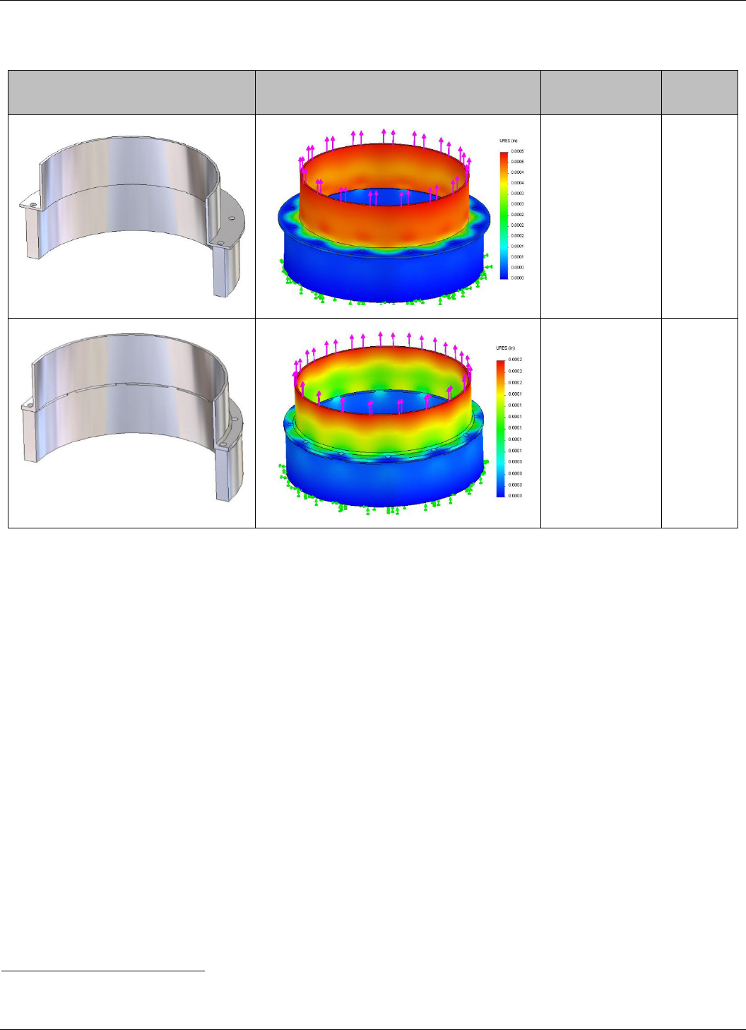
ALB. As the analysis in Table 4-3 shows, thick flanges, small moment arms, and chamfers (or large radii) create much stiffer and lighter structures.
Design Deflection Plot Design Notes
Max
Deflection
Value [in]
• Flanges too thin
• Moment arms too
large
• No chamfer or
fillet
0.0005
• Thicker flanges
• Smaller moment
arms, but fits
fasteners
• Chamfer added
for stiffness
• No significant
increase in mass
0.0002
Table 4-3: Features of adjoining structure
1
The stiffness of flanges is important relative to overall stack stiffness. If the flange stiffness is too low, the first mode lateral frequency of the entire
stack can decrease detrimentally. For proper operation of the ALB, the flanges should be stiff enough to guarantee the preload of the ALB will not
excessively warp the adjoining structure and vice-versa.
The stiffness increase associated with straight load-paths is illustrated below. A straight load path can double the stiffness and increase lateral
frequencies by 40%.
Fasteners must be installed at every location in order to integrate the ALB. Do not skip a bolt as this will substantially decrease strength and stiffness
of the ALB.
The thermal extremes of the bolted joint often drive the selection of fasteners. Users anticipating temperatures beyond +10 to +50°C should examine
the preload changes associated with coefficient of thermal expansion (CTE) mismatch. In the past, missions on the Space Shuttle have driven
bolted joint design to extremes because joints are expected to survive landing loads at very low temperature (-40°C). NASA-STD-5020 document
outlines a thorough bolted joint analysis.
Stiffness is affected by bolted joints. A well designed bolted joint leads to greater stiffness and is less susceptible to slipping or gapping.
1
The lower cylinder represents a Lightband. The upper cylinder with flange represents an adjoining structure. The applied load is 1,000 lb. The
materials are aluminum.

2003336C Advanced Lightband User's Manual PSC by Rocket Lab
February 2023 https://www.rocketlabusa.com/space-systems/separation-systems/ Page 14 of 41
Figure 4-7: Straight load-paths from adjoining structures substantially increase stiffness
Figure 4-8: Structures with stiffest flange design. Moment arms in the flange are minimal, maximizing stiffness and strength
As noted in Table 3-1, there are two sets of required flatness for adjoining structure values. Though somewhat subjective, if the adjoining structure is
relatively stiff, the required flatness will be tighter than if the adjoining structure is relatively flexible. A relatively flexible structure will conform to the flat
interface better than a relatively stiff one.
The type of adjoining structure can also have an effect on operation and integration of the ALB. Users should be aware of the effects of their choice
of adjoining structure before integration and adequately plan for any likely issues. See following table.

2003336C Advanced Lightband User's Manual PSC by Rocket Lab
February 2023 https://www.rocketlabusa.com/space-systems/separation-systems/ Page 15 of 41
Table 4-4: Comparison of ALB adjoining structures

2003336C Advanced Lightband User's Manual PSC by Rocket Lab
February 2023 https://www.rocketlabusa.com/space-systems/separation-systems/ Page 16 of 41
4.9 Line Load Limits
Line loading in the X
LB
axis arises from loads in the X
LB
direction and moments about the Y
LB
or Z
LB
axis. Generally, the moments about Y
LB
and Z
LB
generate higher line loading than axial loads. In other words, lateral load cases are typically the limiting factor in strength margin.
Figure 4-9: Line loading forces
Each Leaf corresponds to thru holes for fastening to the adjoining structures. The thru-holes are sized for 0.25-inch socket head cap (SHC) screws.
PSC-RL analysis and tests have shown that the as-designed fastener hole size and spacing is optimum for ALB operation. All testing at PSC-RL is
performed with 0.25-inch fasteners because PSC-RL test cells have 0.25-28 UNF accepting threads.
Axial line loading arises from axial (X
LB
) and lateral (Y
LB
or Z
LB
) loading and moments about Y
LB
or Z
LB
, whereas shear line loading arises from lateral
(Y
LB
or Z
LB
) loading and moments about X
LB
. In flight, lateral loads tend to make the greatest contribution to line loading. Maximum lateral load and
axial load do not occur at the same location on the ALB and standard PSC-RL strength testing reflects this fact.
Note: PSC-RL documentation sometimes expresses line loading in terms of force/Leaf instead of force/bolt. ALB’s have 1 less Leaf than bolt, but the
difference in line load value from this computation method is accounted for in PSC-RL qualification testing. Thus, the terms force/Leaf and force/bolt
are interchangeable.
The equations below provide an approximation of the line loading for initial sizing purposes. They will not however account for peaking due to
stiffness variation of adjoining structures (e.g. base plate stiffening ribs, access cutouts, walls, etc.). They also do not account for non-uniform load
distribution resulting from significant lateral CG offsets. Customers should incorporate the ALB finite element model in their flight stack to determine
the actual load distribution around the ALB. This will expose peaking and inform any derating. Naturally customers should avoid structural
discontinuities to retain high line load margin.
Magnitude of maximum axial line load is given by Equation (1). Direction of maximum axial line load is the same as F
X
.
P
=
|
|
n
+
4
|
VX
|
nD
(1)
Where:
P
eq
is maximum axial line loading [force per bolt]
F
X
is axial force [force]
n is the number of fasteners in the bolt circle [-] (n is one more than the number of Leaves)
V is lateral force [force]
X is the distance from the ALB origin to the load application point in the x direction (typically the center of mass in X direction) [length]
D is the bolt circle diameter [length]
Magnitude of maximum shear line loading is given by Equation (2):
Q =
2
n
V +
|M
|
D
(2)

2003336C Advanced Lightband User's Manual PSC by Rocket Lab
February 2023 https://www.rocketlabusa.com/space-systems/separation-systems/ Page 17 of 41
Where:
Q is the maximum shear line load [force per bolt]
V is the lateral force [force]
n is the number of fasteners in the bolt circle [-] (n is one more than the number of Leaves)
D is the bolt
circle diameter [length]
M
X
is the maximum applied torsional moment about the X
LB
axis (typically negligible in-flight loading) [force x length]
The line load operating limits of P
eq
and Q in Table 3-1 were established by applying loads (Fx and V) to an ALB in qualification strength tests. The
computed line loading was reduced to establish the operating limits shown in Table 3-1. In the strength tests, the distribution of load is discontinuous
because the Stow Screw occupies the space of one Leaf. Therefore, the Leaves adjacent to the Stow Screw will carry a higher percentage of load.
Thus, in test, the actual line loading was higher. This peaking is naturally accounted for with equations 1 and 2.
Typically, customers launch spacecraft with a maximum line loading that is half of the operating limit because they are typically attempting to
maximize stiffness (which tends to produce lower line loading).
Figure 4-10: A round separation system and a square satellite can create high line loading
4.10 Fatigue Limits & Mass-Loaded Vibration
Fatigue failure is generally defined as failure due to cyclic loading. Fatigue failure is typically manifested in a flight stack as a loss of preload in
fasteners, a breakdown of surface treatments at separable interfaces, or cracking of materials. Fatigue can be induced by static, dynamic and
thermal environmental loads. Loading can be locally amplified when dissimilar structures (ex. round to square) are joined to the ALB. The ALB’s load
limits are based on quasi-static strength testing.
When derating the ALB’s maximum load capability from Table 3-1 consider all loading events including mass loaded random vibration, sine sweep,
sine burst and shock testing as well as flight environments. The customer shall use an equivalent fatigue damage approach to properly account for
the combined effects of all loading. See section 7.8 for qualification fatigue testing performed on the ALB. The line loads shown are axial.
Mass-loaded vibration will generate cyclic loading on the ALB dependent on the adjoining structure and payload stiffness and damping. This will
often result in loads far greater than those calculated in Section 4.9 using quasi-static load factors. Flight ALBs should not be used for mass-loaded
vibration testing. If mass-loaded vibration testing is required by the launch provider a waiver should be requested given the ALB’s qualification or an
EDU ALB shall be used. Further, all test and flight environments shall be accurately predicted using a finite element model of the ALB and payload.
During testing, the test results shall be continually compared to analytical predictions for sufficient agreement.

2003336C Advanced Lightband User's Manual PSC by Rocket Lab
February 2023 https://www.rocketlabusa.com/space-systems/separation-systems/ Page 18 of 41
4.11 Flatness and Parallelism
Prior to joining, the surfaces adjoining the ALB should be flat to the specification defined in Table 3-1.
Figure 4-11: An MLB attached to a launch vehicle cone and CAD model showing resulting stress peaking that occurs when adjoining two
warped surfaces
When the adjoining vehicles are extremely warped or surfaces are not parallel, an attempt to join the ALB to both adjoining structures may break or
damage the ALB. Joining an ALB to only one adjoining structure will generally not increase stress because separation systems are designed to be
more flexible than adjoining structures.
It may be tempting to design flexible features to attenuate stress exhibited in the warped structures that are joined. However, this can lead to an
unacceptably low stiffness and first mode frequency of the entire system. To achieve both a low stress and high stiffness system, flatness of the
adjoining structures must be controlled.
Isolation systems like Moog CSA Engineering’s SoftRide intentionally add flexibility to joints to attenuate response. Furthermore, isolation systems
offer an additional benefit in the substantial relaxation of adjoining structure flatness requirements.
Finite element models (FEMs) nominally assume perfect flatness of adjoining structures. Therefore, FEMs can obscure this potentially significant
reduction in structural margin.
Figure 4-12: FEM simulates a clamp band separation system via radially inward preload from band tension. Warping can result

2003336C Advanced Lightband User's Manual PSC by Rocket Lab
February 2023 https://www.rocketlabusa.com/space-systems/separation-systems/ Page 19 of 41
Figure 4-13: A deflection of 0.004 inches at the interface to adjoining structures is created by preload
ALBs and clamp bands embody the challenging nature of mechanical assembly; not only do they warp in proportion to preload, but a warp applied to
them can affect their preload. Critically, as many mechanisms engineers have observed in test, the structural performance (strength and stiffness) is
highly correlated to preload. PSC-RL engineers often observe changes in internal strain as structures are joined to the ALB. A 20% change in
preload as the separation system is fastened to an adjoining structure has been observed.
Easily fabricated structures adjoining separation systems may be expensive to make flat. Alternatively, structures that may be expensive to fabricate
can be easy to make flat. For example, a thrust cone that interfaces the final stage engine to the launch vehicle can be easily made by riveting
machined rings to conical sheets. The riveting process can stress the thrust cone. This may manifest itself as warping (a lack of flatness) when the
riveted structure is removed from its much more rigid tooling. To attain flatness requirements, the riveted structure must be machined or shimmed at
additional cost. As a more expensive option, the thrust cone could be directly machined from a conical forging ensuring flatness requirements are
met.
Engineers should consider the fact that all manufacturing and joining processes (riveting for assembly, fastening to adjoining structures, curing of
composites) increase strain energy and thus will warp structures.

2003336C Advanced Lightband User's Manual PSC by Rocket Lab
February 2023 https://www.rocketlabusa.com/space-systems/separation-systems/ Page 20 of 41
4.12 SoftRide and ALB
The SoftRide Isolation System is a spacecraft vibration and shock isolation system designed to reduce launch vehicle-induced loading on the
spacecraft. SoftRide is a patented product of Moog CSA Engineering (www.csaengineering.com). It has been flown successfully many times.
Bicycle
Car
Aircraft
Spacecraft
Table 4-5: Valuable payloads are isolated from detrimental external loading using spring-damper (isolation) systems
SoftRide Systems have several benefits when used in conjunction with the ALB:
1. Substantially reduce flight loads into the payload such as engine transients, random vibration, and shock.
2. Substantially reduce risk by isolating the payload from unanticipated launch load events.
3. Substantially increase damping. SoftRide damping ratio range is 3% to 25% depending on the needs of the mission.
4. Reduce stiffness requirements of the space vehicle because there is less value to a very stiff bus if it is sitting on a very flexible isolation
system.
5. Reduce flatness requirements of adjoining vehicles because the isolation system is flexible.
6. Ease integration of the ALB by eliminating the need to stow the ALB to join the satellite to the launch vehicle. With the isolation system
attached to the already stowed ALB, integration can occur by simply fastening the launch vehicle to the isolation system.
Figure 4-14: Moog CSA’s SoftRide OmniFlex which isolates the satellite from the launch vehicle loads
Isolation systems add mass that is usually small compared to the spacecraft mass. In fact, the mass added by SoftRide is often nullified because the
ALB has a lower mass than other separation systems. Isolation systems require a displacement stroke to attenuate dynamic loads.
4.13 Lifecycle
An ALB cycle is defined as one stow and one separation. Refer to Table 3-1 for max number of cycles (Noted as Life, Deployments). If cycles equal
or exceed the allowable, the unit must be returned to PSC-RL for inspection and possible refurbishment. Contact PSC-RL for pricing and schedule.

2003336C Advanced Lightband User's Manual PSC by Rocket Lab
February 2023 https://www.rocketlabusa.com/space-systems/separation-systems/ Page 21 of 41
4.14 Rotation Rates
Rotation rates are induced by the distance between the payload’s center of mass (CM) and the center of the ALB’s spring force. Rotation rates may
be about any axis of a space vehicle as a result of the separation event.
Rotation rates can be estimated via Equation (3). There are many variables that contribute to this rate and several simplifying assumptions have
been made to compensate. Equation (3) assumes the adjoining vehicle is many times more massive (>10X) and has many times more inertia (>10x)
than the separating vehicle. It also assumes the pre-separation rates are all zero. Only Separation Reliability testing can produce verifiable values
for rotation rates.
Figure 4-15: CM offset and rotation rate
w =
mvd
I
(3)
Where:
w is the payload rotation rate [rad/s]
m is the mass of the payload [mass]
v is the relative velocity [length/s]
d is the distance between the CM and the resultant location of the Separation Springs [length]
I is the mass moment of inertia about the center of mass of the separating vehicle [mass∙length
2
]
Figure 4-16: An illustration of Equation 4
The Separation Spring configuration may be adjusted on the ALB so the Springs, as a sum, act through the CM. Table 3-1 provides all the
information to complete dynamic analysis of the separation event. Though typically trivial, even the effect of the spring in the Separation Switches
and Separation Connectors may be incorporated into dynamic models.
Modern CAD models of spacecraft inform designers of the CM location allowing them to control it to within thousandths of an inch prior to
manufacture. Testing has confidently shown that when d = 0.0±.01 in the expected tip-off will be within 2 degrees per second.
Rotation rates can be beneficial. It tends to average out the temperatures on the spacecraft, and if a camera attached to the launch service is
looking at the spacecraft while it is rotating after separation, mission managers can verify configuration in spaceflight. For example, are the stowed
solar arrays intact?
m = 181 kg
v = 0.5 m/s
I = 12 kg*m
2

2003336C Advanced Lightband User's Manual PSC by Rocket Lab
February 2023 https://www.rocketlabusa.com/space-systems/separation-systems/ Page 22 of 41
4.15 Separation Velocity and Separation Springs
Equation (4) is used to calculate the required total separating energy, E, given a desired velocity between the payload and final stage.
E =
(
mM
)
v
2
(
m + M
)
(4)
Equation (5) is used to calculate the estimated number of Separation Springs, S, required given a desired velocity between the payload and the final
stage.
S =
mM
m + M
×
v
2e
(5)
Equation (6) is used to calculate relative velocity, v, between payload and final stage given a known total stored energy.
v =
2E
(
m + M
)
mM
(6)
Where:
m is the payload mass [kg] (includes mass of ALB Upper Ring)
M is the final stage mass [kg] (includes mass of ALB Lower Ring, excludes payload mass)
v is the relative velocity between m and M [m/s] (ΔV or separating velocity)
S is the number of Separation Springs [-] (even qty. preferred)
e = 2.45 J is the stored potential energy of a single Separation Spring that is converted to kinetic energy manifested as v. It includes efficiency losses.
E = S∙e is the total ALB separating energy manifested as v [J] (The stored potential energy of all Separation Springs that is converted to kinetic
energy. It includes efficiency losses. See Table 3-1 for typical ranges for each ALB size.)
Example 1: velocity is known, total separating energy is desired
Payload mass, m = 200 kg
Final stage mass, M = 3000 kg
Desired relative velocity, v = 0.356 m/s
Total Separating Energy, =
(
200 kg × 3000 kg
)
× (0.356
m
)
2 ×
(
200 kg + 3000 kg
)
= 11.9 J
Example 2: total separating energy is known, required number of Separation Springs is desired
Total separating energy, E =11.9 J
Number of Separation Springs, =
11.9
2.45
= 4.86
Example 3: Total separating energy is known, relative velocity is desired
Payload mass, m = 200 kg
Final stage mass, M = 3000 kg
Total separating energy, E =12.25 J
Relative velocity, =
2 × 12.25 J ×
200 kg + 3000 kg
200 kg 3000 kg
= 0.361
m
s
Observe that the quantity and mass of Separation Springs increases with the square of v. A small increase in velocity requires a significant increase
in Springs. The allowable quantity of Separation Springs varies by ALB diameter.
Figure 4-17: The relative velocity (v) is created by the Separation Springs (S)

2003336C Advanced Lightband User's Manual PSC by Rocket Lab
February 2023 https://www.rocketlabusa.com/space-systems/separation-systems/ Page 23 of 41
Figure 4-18: Spring quantity required increases with the square of velocity (springs are lousy rocket engines)
The location of Separation Springs, Separation Connectors, and Separation Switches need not be symmetric to minimize rotation rates. Sometimes
PSC-RL engineers will modify the location (configuration) of Separation Springs to null out rotation rate torques during Separation Reliability tests
(this is a custom test).
When several payloads are on the same launch vehicle, engineers can minimize the possibility of re-contact by varying the separation velocity and
direction. Angling the payloads so they push through the center of mass reduces rotation rate torques and the possibility of re-contact.
The ALB will work without any Separation Springs—it just won’t have any velocity. However, if Separation Connectors or Separation Switches are
installed, the ALB will separate with a very small separating velocity due to the small force of the spring plungers.
Figure 4-19: Spacecraft oriented so they reduce the moment arms between center of force and center of mass

2003336C Advanced Lightband User's Manual PSC by Rocket Lab
February 2023 https://www.rocketlabusa.com/space-systems/separation-systems/ Page 24 of 41
5. Vertical and Horizontal Integration to Adjoining Vehicles
Figure 5-1: Typical vertical and horizontal integration methods
The compliance of the entire stack needs to be assessed to properly integrate the ALB. When the ALB is stowed as part of the integration process,
the entire system will be structurally indeterminate. If the space vehicle and Upper Ring are too far from the Lower Ring or improperly aligned, the
ALB will have to pull the space vehicle down and vice versa. To minimize this effect, a compliance spring and/or a more precise control of space
vehicle position in all six degrees of freedom is necessary.

2003336C Advanced Lightband User's Manual PSC by Rocket Lab
February 2023 https://www.rocketlabusa.com/space-systems/separation-systems/ Page 25 of 41
Figure 5-2: Horizontal and vertical integration
Flatness of the adjoining surfaces should be within the flatness requirement. See Table 3-1. If flatness requirements are not met by the structure,
shims (epoxy or metal) can be used to attain the required flatness.
Flexible adjoining structures may distort while lifting to mate the structures. Simple static analysis can expose any detrimental distortion due to lifting
hard-points and weight.

2003336C Advanced Lightband User's Manual PSC by Rocket Lab
February 2023 https://www.rocketlabusa.com/space-systems/separation-systems/ Page 26 of 41
6. Reliability, Failure Modes and Anomaly Reporting
ALB reliability will be maximized by strictly adhering to the procedures in this document. Over a thousand separation tests on more than 20 ALBs
before, during, and after critical development and qualification tests (thermal-vacuum, shock, vibration, strength, separation reliability, etc.) over
several years show reliability and confidence.
6.1 Failure Modes, Effects and Preventative Actions
Failure Mode
Effect(s)
Preventative Action
Operator fails to remove Stow Screw prior to
initiation
Failure to separate
Follow procedures
Operator fails to remove Spring Locks prior to
initiation
Lower separation velocity and/or higher
rotation rates
Follow procedures
Initiator voltage or current is too high or too low;
too short or too long
Failure to initiate or damage to initiator
Follow procedures
Subsystems loosen (Switch, Connector, Spring)
Decreased performance, debris
Verify and record torque at all
fasteners joining subsystems
Cross-threading screw
Screw is seized, proper assembly is
prevented
Verify all screws and their
accepting threads are within
specification and free running
Flatness of interfacing boundaries are out of
tolerance.
System will not stow or will be difficult to
stow.
Inspect boundary interfaces
FOD in DE-9 connector
Increased electrical resistance
Inspect and clean pins and
sockets prior to mate
Operator fails to follow stow procedure, exceeds
max torque or max turns
ALB detrimentally damaged, requires PSC-
RL rework
Procedures, checklists, PSC-RL
provided training
Loopbacks in Separation connector are too long
to allow proper seating of Matrix
Pins are damaged
Verify Matrix seats properly
before integration to ALB
Stow screw torque is exceeded or operator turns
past ‘Ping’
ALB won’t deploy
Adhere to operating procedures,
checklists and training
Table6-1: Failure Modes, Effects and Preventative Actions

2003336C Advanced Lightband User's Manual PSC by Rocket Lab
February 2023 https://www.rocketlabusa.com/space-systems/separation-systems/ Page 27 of 41
7. Testing
PSC-RL completes acceptance testing on standard flight ALBs prior to delivery. EDU ALBs only receive build verification tests. PSC-RL’s testing of
the ALB does not include the customer’s wiring harness. Typically, Transition Rings are fastened to the ALB during testing to mimic flight-like
structural, thermal, and dynamic boundary conditions. There is no fixed sequence for acceptance tests. PSC-RL writes, executes, and approves all
test plans. PSC-RL also takes any corrective action if anomalies arise. PSC-RL may employ a lot testing strategy, at PSC-RL discretion (i.e. all units
within one lot may not receive all testing).
Special (Custom) testing is not included and adds cost and schedule.
Test
Standard or
Special?
Build Verification (pre-BCR)
Standard
Random Vibration Test
Standard
Thermal Vacuum Test
Standard
Separation Reliability Test
Special (Custom)
Strength Test
Special (Custom)
Shock Test
Special (Custom)
Table 7-1: Standard vs Custom test summary
7.1 Test Summary
These values may be exceeded at PSC-RL’s discretion.
Test
Parameter
Qualification
Protoflight
Flight (Acceptance)
EDU
Build
Verification
Preload Tuning [-]
proprietary
proprietary
proprietary
proprietary
Benchtop Operations [-]
≥7
≥7
≥7
≥7
Random
Vibration
Level [grms], ± 1 dB
14.1
14.1
10.0
Not Performed
Duration [s/axis], +10%/-0%
180
60
60
TVAC
Temp [°C], ±3.0 °C
-50 to 110
-29 to 66
-24 to 61
Not Performed
Cycles, min [-]
10
8
4
Separations [-]
6
2
1
Shock
Levels
See Figure 7-4
See Figure 7-4
Not Performed Not Performed
Impacts/axis
3
2
Strategy
positive & negative
maxi max
Separation
Separations, min [-]
100
5
Not Performed
Not Performed
Strength
Axial Line Load [lbf/bolt]
2064
Not Performed Not Performed Not Performed
Shear Line Load [lbf/bolt]
775
Fatigue
Axial Line Load [lbf/bolt]
See Figure 7-7
Not Performed Not Performed Not Performed
Cycles
See Figure 7-7
Table 7-2: Test Summary
7.2 Build Verification
The ALB is tuned to achieve optimal retention and separation characteristics. Throughout build the ALB is stowed and deployed to verify nominal
operation. The Springs elongate, and the Separation Switches and Separation Connectors change state. Transition Rings are fastened to the ALB to
produce flight like structural boundary conditions. These verifications are completed during the build process prior to Build Complete Review (BCR)
and do not have stand-alone test procedures.
Figure 7-1: Benchtop Separation Testing
Qualification Proto-Flight Acceptance (Flight) EDU
Benchtop Separations Separations [-] >100 ≥7 ≥7 ≥7
Te st
Parameter
Use

2003336C Advanced Lightband User's Manual PSC by Rocket Lab
February 2023 https://www.rocketlabusa.com/space-systems/separation-systems/ Page 28 of 41
7.3 Component Random Vibration
The ALB is exposed to random vibration in three orthogonal excitation axes to verify workmanship and demonstrate a capability to survive transport
or flight vibration.
Figure 7-2: Random Vibration Testing
7.4 Thermal Vacuum
The ALB is exposed to temperatures and pressures of spaceflight. ALB is initiated and separated in a vacuum at a temperature extreme and
initiation voltage extreme.
Figure 7-3: TVAC Testing
Qualification Proto-Flight Acceptance (Flight) EDU
Level [g
rms
] 10±1dB
Duration [s/axis] 180+18/-0 60+6/-0 60+6/-0
Excitation Axes [-]
Component Random Vibration
14.1±1dB
Not Performed
X, Y, Z
Te st
Parameter
Use
0.010
0.100
1.000
10 100 1000
ASD [g
2
/Hz]
Frequency [Hz]
Qual/Proto
Acceptance
Qualification Proto-Flight Acceptance (Flight) EDU
Temperature (
±3) [°C] -50 to +110
-29 to +66 -24 to +61
Pressure [Torr]
Cycles [-]
≥10 ≥8 ≥4
Separations [-] ≥6
2 1
Te st
Parameter
Use
Thermal Vacuum
Not Performed
<1.0E-4

2003336C Advanced Lightband User's Manual PSC by Rocket Lab
February 2023 https://www.rocketlabusa.com/space-systems/separation-systems/ Page 29 of 41
7.5 Shock (Custom Test)
The ALB is exposed to simulated flight shock.
Figure 7-4: Shock Testing
7.6 Separation Testing (Custom Test)
The ALB is separated repeatedly to monitor nominal operation. This may be performed as a benchtop test or on the PSC-RL Separation Reliability
fixture, a 5 degree of freedom air bearing table. During Separation Reliability, tip-off rates and separation energy are measured and recorded.
Figure 7-5: Separation Reliability Testing
Qualification Proto-Flight Acceptance (Flight) EDU
Shock Level [g] Not Performed
Not Performed
See following figure
Te st
Parameter
Use
1
10
100
1,000
10,000
100 1,000 10,000
Acceleration [g]
Frequency [Hz]
Qual
Protoflight
Qualification Proto-Flight Acceptance (Flight) EDU
Separation Testing Operations [-] 100 5 Not Performed Not Performed
Te st
Parameter
Use

2003336C Advanced Lightband User's Manual PSC by Rocket Lab
February 2023 https://www.rocketlabusa.com/space-systems/separation-systems/ Page 30 of 41
7.7 Strength (Custom Test)
The ALB is exposed to line loading at the specified limits. Reactions in the ALB may be produced with sine-burst testing or with hydraulic rams. Sine-
burst testing requires a PSC-RL supplied mass simulator.
Figure 7-6: Strength Testing
7.8 Fatigue (Custom Test)
The ALB is cyclically loaded. Reaction forces are excited through dynamic loads, reaching a prescribed line load to a required number of cycles. A
PSC-RL supplied mass simulator is required.
Figure 7-7: Fatigue Testing
Qualification
Proto-Flight Acceptance (Flight)
EDU
Axial Line Load (Peq)
[lbf/bolt]
2064
Shear line load (Q)
[Lbf]
775
Parameter
Use
Te st
Strength (sine burst or static)
Not Performed
Not Performed
Not Performed
Qualification Proto-Flight Acceptance (Flight) EDU
Axial Line Load [lbf/bolt]
1188 | 893 | 670
Cycles [-]
100 | 800 | 10000
Fatigue (sine burst or sine dwell)
Not Performed
Not Performed
Not Performed
Te st
Parameter
Use
0.0
0.2
0.4
0.6
0.8
1.0
1.2
1.4
1.6
1.8
2.00
[s]
-12
-10
-8
-6
-4
-2
0
2
4
6
8
10
[g]
Chan. no: 22
Chan. type: M
Level: 0.0 dB
Resolution: 2.44e-004
Unit: g
Peak (curr.): 10.17 g
Peak (ref.): 9.87 g
-- Pulses on curr. level
done: 1
remaining: 9
-- Pulses total --
done: 14
remaining: 15
Date: 02-19-20
Time: 13:57:07
Product version:
VTL-20-018
Y-axis, Run #002
Operator: Luke Boggs
Program: PSC
Test Engr: Chris Flood
Item: ALB-8
Y-axis Qual Sine Burst,
Budget: EEP22XXX
R6Y, Stack CM +Z
Shock SRS
Test Engr: Chris Flood
Item: ALB-8
Y-axis Qual Sine Burst, ALB-8 Load Case #001

2003336C Advanced Lightband User's Manual PSC by Rocket Lab
February 2023 https://www.rocketlabusa.com/space-systems/separation-systems/ Page 31 of 41
8. Specifying an ALB
8.1 Determine stiffness requirements
The biggest driver in ALB diameter selection should be payload stiffness requirements. From dynamic envelope mission requirements, determine
the required axial and lateral stiffness of the payload stack. The minimum ALB diameter can then be selected from Table 3-1. However, it is prudent
to choose an ALB diameter larger than necessary to provide additional stiffness margin at less than an equivalent increase in weight. For example, a
15-inch diameter ALB is about 6.6 times stiffer than an 8-inch diameter ALB but weighs less than twice as much.
8.2 Determine strength requirements
From your expected mission loads on the payload, calculate maximum line load. Verify that mission loads required to attain those line loads are less
than maximum ALB loads shown in Table 3-1. If not, increase the chosen ALB diameter until allowable line load is achieved. PSC-RL will request
mass of payload, center of mass location (in ALB coordinate system), and quasistatic load factors at Kick-off to verify adherence to strength
requirements.
8.3 Select ALB Bolt Circle diameter
Choose an appropriate ALB diameter from Table 3-1 based on stiffness and strength.
8.4 Complete virtual fit check and plan logistics
Integrate both the ALB stay-out zone model and a CAD model of the ALB (download from www.planetarysystemscorp.com or contact PSC-RL) with
a model of your payload and verify your fit requirements. Pay close attention to all stay-out zones per Table 3-1 as the CAD model may not
represent the maximum travel of all components. Remember to include your wiring harness. Also determine how you will fasten and operate the ALB
for shipment, testing and final integration procedures. Determine the electrical and mechanical ground support equipment (GSE) needed.
8.5 Separation Switch quantity (SW)
The greater the quantity of Separation Switches, the more complex and heavier the harness. See Table 3-1 to ensure the total quantity of
Separation Switches and Separation Connectors does not exceed the maximum allowable.
8.6 Separation Connector quantity (SC)
As with Separation Switches, fewer Separation Connectors allow for a simpler harness. Connectors are specified as pairs, so one Connector
consists of both the Lower and Upper halves. See Table 3-1 to ensure the total quantity of Separation Switches and Separation Connectors does
not exceed the maximum allowable.
8.7 End Use (FLT or EDU)
Engineering Development Unit (EDU) ALBs receive only a bench-top separation test. They do not receive acceptance testing and shall not be used
for flight. As such, EDUs are indelibly marked “NOT FOR FLIGHT.”
Flight Units (FLT) receive testing per Section 7 prior to shipment. If special testing is required (shock, strength, separation reliability, off-set center of
mass separation reliability, etc.) additional schedule and cost is typically incurred.
EDU and FLT ALBs are built using the same materials and processes. Customers often purchase an EDU in addition to a FLT for fit checks and
ground testing.
8.8 Separation Springs
Use Equation (5) to specify the number of Separation Springs that creates the desired separating velocity or separating energy. A standard ALB
comes with 3 Separation Springs (~7.4 J) or 4 Separation Springs (~9.8 J) depending on the diameter of the Lightband (refer to Table 3-1).
Additional Separation Springs can be purchased for customer installation. More than n/4 or less than the standard quantity of Separation Springs is
a custom unit.
8.9 Specifying ALB
Use the following convention to specify the ALB: ALBXX-SW-SC-FLT-XX
Required
Prefix
Bolt Circle
Diameter
(rounded down)
Separation
Switch
Qty.
Separation
Connector
Qty. [pairs]
End Use
(Flight or
EDU)
Separation
Springs [-]
ALB
XX
SW
SC
FLT
XX
Table 8-1: ALB specification convention
For example, ALB11-1-2-FLT-3 specifies
• ALB – Advanced Lightband
• 11 – 11.732-inch bolt circle diameter
• 1 – Separation Switch
• 2 – Separation Connector pairs (2 Lower and 2 Upper)
• FLT – Be used for space flight and thus receive testing
• 3 – Separation Springs, separating kinetic energy of ~7.4 J

2003336C Advanced Lightband User's Manual PSC by Rocket Lab
February 2023 https://www.rocketlabusa.com/space-systems/separation-systems/ Page 32 of 41
9. Purchasing, Deliverables, & Schedule
9.1 Purchasing an ALB
Contact PSC-RL directly to receive the most up-to-date ALB prices. The standard payment schedule is shown below.
Event
Payment [%]
After Kick-off Meeting
35
Build complete review (BCR) completion
45
Shipment
20
Table 9-1: Standard ALB schedule
9.2 Standard Delivery Schedule
Standard ALBs are typically delivered in 30 weeks ARO. Expedited delivery is available at an additional cost. Custom or Special testing (e.g., shock,
strength, separation reliability, CM off-set separation reliability, etc.) increases schedule and cost.
9.3 ALB Deliverables
The items included in the price of an ALB and delivered to the customer are:
1. The ALB(s)
2. Certificate(s) of conformance
9.4 ALB STEP Files
STEP files of simplified ALB assemblies are available to prospective users and customers. Users may request a STEP model at
www.planetarysystemscorp.com
.
Note: ALB STEP models do not show all components or their full extent of travel. Users shall not use simplified ALB STEP models to verify
clearance. Instead use the stay-out zone CAD models for clearance verification.
9.5 ALB Finite Element Models
PSC-RL has test-verified finite element models (FEM) of ALBs available for customers. To accurately predict line loading through the ALB,
customers should incorporate the FEM into their flight stack model. Contact PSC-RL for further information. FEMs may incur an additional cost. This
item is subject to US Export Control regulation.
9.6 Custom Units
ALB is a COTS separation system. Any customization (e.g., testing, configuration, program management, additional customer requirements,
accelerated schedule, etc.) will incur additional cost and schedule. Figure 9-1 has a summary checklist to compare standard vs custom ALBs, the
custom list is not all-encompassing (there may be additional unlisted items which necessitate a custom unit).
Figure 9-1: Standard vs. Custom Lightband
9.7 Accessories
Separation Switches, Separation Connectors, and Separation Springs, may be delivered earlier than the ALB. Accessories delivered not attached to
a flight ALB will not receive testing. PSC-RL does not install spare accessories for testing as a standard service. Accessories may be installed at any
step through build and test. Separation Connectors and Separation Switches may not receive the full suite of testing. All Accessories should be
listed as individual line items on the PO/contract. All PSC-RL paperwork will list parts as individual line items.
9.7.1 Separation Connectors
Separation Connectors are sold in pairs (an -Upper and -Lower half). Each half will be listed as an individual line item.
• 4000932-Upper, ALB Separation Connector Assembly Upper
• 4000932-Lower, ALB Separation Connector Assembly Lower
Note: Quantity 2 (per half, 4 per pair), NAS1352N06-7, .138-32 x .438 SHC Screws, are required to attach the ALB Separation Connector to the ALB
Upper/Lower Ring. PSC-RL does not sell fasteners and does not include loose fasteners when accessories are not attached to the ALB.

2003336C Advanced Lightband User's Manual PSC by Rocket Lab
February 2023 https://www.rocketlabusa.com/space-systems/separation-systems/ Page 33 of 41
9.7.2 Separation Switches
Two parts are typically ordered for each Separation Switch (if procuring flight spares, only the Switch needs to be procured):
• 4000952 Separation Switch (includes a .375-32 x .625 x .094 thin hex nut) - this is the actual switch.
• 4000922 ALB Switch Bracket – this bracket is required to attach the switch to the ALB.
Note: Quantity 2, NAS1352N06-7, .138-32 x .438 SHC Screws, are required to attach the ALB Switch Bracket to the ALB Upper/Lower Ring. PSC-
RL does not sell fasteners and does not include loose fasteners when accessories are not attached to the ALB.
9.7.3 Separation Springs
Three parts make up a single Separation Spring
• 4000920 ALB Spring Stop
• 4000921 ALB Spring Guide
• Separation Spring, 1.06 x .79 x 53.2 Compression Spring
Note: Quantity 1, NAS1352N3-10, .190-32 x .625 SHC Screw, is required to attach spring parts to an ALB Lower Ring. PSC-RL does not sell
fasteners and does not include loose fasteners when accessories are not attached to the ALB.
To stow the Spring an ALB Spring Lock is required. See Section 12.
10. Manufacturing Process
Employees at PSC-RL design, assemble, and test separation systems. PSC-RL is an AS 9100-compliant organization. All of the machining and
fabrication is completed by vendors qualified to PSC-RL’s standards. PSC-RL maintains documentation of all tasks associated with flight hardware
procurement, inspection, storage, assembly, test, and shipment. All of these are enveloped by PSC-RL’s quality management program. Procuring,
manufacturing, and stocking are controlled by inventory management software. ALBs and their subsystems are tracked and completely traceable
using their purchase order, serial number, or lot number. Just like in testing at PSC-RL, manufacturing is done in teams. Two employees typically
sign-off on steps in manufacturing procedures (one acts as the technician, the other as quality assurance) and execute a Build Complete Review
(BCR) as the final step in the completion of the manufacturing procedures. PSC-RL writes, executes and approves manufacturing procedures. PSC-
RL also takes any corrective action if anomalies arise. The customer-furnished wiring harness is not included in the manufacturing of an ALB.
11. ALB Testing and Procedures Performed by Customer
Customers often complete some of these tests and procedures after receiving the ALB.
Test or procedure
Objective
Remarks and cautions
ALB training
Learn how to operate ALB and uncover
unexpected potential integration difficulties
Verify operators are trained to operate the
ALB
Fit check to adjoining structures Verify bolt patterns and clocking
Is the electrical wiring harness attached
during this procedure?
System-level vibration test Verify workmanship and modes
Will the ALB be overloaded at resonance? Are
notching or force limiting methods employed?
EDU ALBs are great for this test.
Electrical initiation test
Verify the initiation circuit and power system
from the launch vehicle will initiate the ALB
within specification. Verify adjoining vehicles
will receive the proper signal upon separation.
Ensure ALB operation procedures are being
followed.
Table 111-1: Testing and other procedures
Figure 111-1: Electro-mechanical fit check and a separation test

2003336C Advanced Lightband User's Manual PSC by Rocket Lab
February 2023 https://www.rocketlabusa.com/space-systems/separation-systems/ Page 34 of 41
12. Ground Support Equipment (GSE)
For program planning, several pieces of GSE are listed below that have been useful to customers in the past.
Item
Description
Graphic
Transition Ring
NOT SUPPLIED
NOR SOLD BY
PSC-RL
Fastens to the Upper or Lower Ring.
Useful to attenuate flatness issues of
adjoining structures, allow access to
fasteners, simulate stiffness of adjoining
structure
Vibration Adapter
Plate
NOT SUPPLIED
NOR SOLD BY
PSC-RL
The interface between an electro-dynamic
exciter and the ALB or a Transition Ring.
Oscilloscope,
probes, power
supply, 1.0Ω (10W)
and 8.0 Ω (150W)
resistors, 2x DE-9
breakout cables and
various banana jack
cables
NOT SUPPLIED
NOR SOLD BY
PSC-RL
Used to deploy, initiate, and
record V and I
Stow Screw
ONE SUPPLIED
WITH EACH ALB
Used to Stow ALB
Spring Lock
ONE SUPPLIED
WITH EACH
SPRING
Used to hold Separation Spring in stowed
state

2003336C Advanced Lightband User's Manual PSC by Rocket Lab
February 2023 https://www.rocketlabusa.com/space-systems/separation-systems/ Page 35 of 41
Item
Description
Graphic
Crane Compliance
Sling
NOT SUPPLIED
NOR SOLD BY
PSC-RL
Allows for compliance when mating
adjoining vehicles with the ALB
Turned-down flat
head screws
NOT SUPPLIED
NOR SOLD BY
PSC-RL
Align an Upper or Lower ring to an
adjoining structure
1.0 inch long, #2-
56 screw
Typically SUPPLIED
BY PSC-RL
Aids in Separation Connector assembly
Table 122-1: Ground support equipment

2003336C Advanced Lightband User's Manual PSC by Rocket Lab
February 2023 https://www.rocketlabusa.com/space-systems/separation-systems/ Page 36 of 41
13. Warranty and Glossary
13.1 Warranty
The ALB warranty is defined in Planetary Systems Corporation Commercial Terms and Conditions of Sale (Doc. 1001112)
13.2 Glossary
• ALB: Advanced Lightband
• ARO: After receiving order
• Bench-top testing: A separation test of the ALB on a bench top. Rate and velocity information are not recovered.
• Build Complete Review (BCR): Verify product assembly is complete (and hence ready for test). This includes bench-top separation.
• CAD: Computer Aided Design
• CCW: Counterclockwise
• CM: Center of mass (also known by center of gravity, CG)
• CRES: Corrosion Resistant Steel
• CTE: Coefficient of thermal expansion
• CVCM: Collected volatile condensable material
• CW: Clockwise
• Engineering development unit (EDU): An ALB designated for use on the ground to allow engineers to use flight like hardware. EDU are
not exposed to testing, they only receive several bench-top separation tests prior to delivery
• EMF: Electromotive Force
• FEA: Finite element analysis
• Flight Unit: An ALB designated for use as a hardware that will fly into space. Flight units are exposed to acceptance testing prior to
delivery
• FMEA: Failure modes and effects analysis
• FOD: Foreign object debris, any article or substance, alien to a space vehicle or system, which could potentially cause damage
• GSE: Ground support equipment
• IAW: In accordance with
• Inch (in): English unit of distance
• Initiation: The Upper and Lower halves of the ALB unlock
• IPA: Isopropanol (Alcohol)
• LV: Launch vehicle
• MLB: Motorized Lightband (version preceding the ALB)
• MOI: Moment of inertia
• Nominal Operation: Separation of the ALB at 23 ±10°C, initiated within limits of Table 3-1
• Payload: Spacecraft or space vehicle (used interchangeably)
• Pound (lb): English unit of weight
• Quality Management System (QMS): Policies, processes and procedures required for planning and executing business
• Separation: The Upper and Lower halves of the ALB unlock, and the Separation Springs elongate to end of travel
• SHC: Socket Head Cap Screw
• Spacecraft or Space vehicle: payload (used interchangeably)
• SRS: Shock response spectrum
• Standard for the Exchange of Product model data (STEP): A file format used to share CAD files governed by ISO10303-21
• Stow: To mechanically join the Upper and Lower halves of the ALB
• TML: Total mass loss
• Transition Ring: custom aluminum interface rings attached to the ALB. Used to emulate flight boundary conditions and ease bolt
attachment.
• WRT: With respect to

2003336C Advanced Lightband User's Manual PSC by Rocket Lab
February 2023 https://www.rocketlabusa.com/space-systems/separation-systems/ Page 37 of 41
14. Appendix A: ALB Accessories
Figure 14-1: ALB Accessories
14.1.1 ALB Separation Connector
PSC-RL has developed a 30 pin Separation Connector for use with the ALB. This connector has been spaceflight qualified alongside the ALB and
has flight heritage.
Separation Connectors pairs have two parts: a -Upper and -Lower half.
• 4000932-Upper, ALB Separation Connector Assembly Upper
• 4000932-Lower, ALB Separation Connector Assembly Lower
Note: Quantity 2 (per half, 4 per pair), NAS1352N06-7, .138-32 x .438 SHC Screws, are required to attach the ALB Separation Connector to the ALB
Upper/Lower Ring. PSC-RL does not sell fasteners.
See Figure 14-2 for overview. See Table 3-1 for parameters, Table 14-1 lists a subset specific to the Separation Connector. See PSL-RL document
3000355 ALB Operating Procedure for attachment. See Section 14.1.4 for wiring details. See Section 9.7.1 for purchasing.
Figure 14-2: ALB Separation Connector Overview
Table 14-1: ALB Separation Connector Parameters
Energy per separation connector [J] Kec 0.001 -
Spring Constant [lbf/in] Kc 38 -
Force per connector, stow ed [lbf] Fs c 5.1 -
Force per connector, deployed [lbf] Fdc 1.9 -
Stroke [in] - 0.110 -
Current, each pin, steady state, vacuum [A] Is c v 3.00 -
Current, each pin, steady state, STP [A] Is c a 5.00 -
Pulsed current through pin [A] Ipv 5.00 -
Mated pin-pair contact resistance [Ohm] Rs c 0.04 ± 0.02
Mated pair mass + fasteners [lbm] - 0.099 ± 0.02
Pin Solder Cup Internal Diameter [inch] Pid 0.05 -
Pin Solder Cup Internal Depth [inch] Pdepth 0.100 -
Separation
Connector

2003336C Advanced Lightband User's Manual PSC by Rocket Lab
February 2023 https://www.rocketlabusa.com/space-systems/separation-systems/ Page 38 of 41
14.1.2 ALB Separation Switch
PSC-RL has developed a Separation Switch for use with the ALB. This switch has been spaceflight qualified alongside the ALB and has flight
heritage.
Two parts make up a Separation Switch:
• 4000952 Separation Switch (includes a .375-32 x .625 x .094 thin hex nut) - this is the actual switch.
• 4000922 ALB Switch Bracket – this bracket is required to attach the switch to the ALB.
Note: Quantity 2, NAS1352N06-7, .138-32 x .438 SHC Screws, are required to attach the ALB Switch Bracket to the ALB Upper/Lower Ring. PSC-
RL does not sell fasteners.
See Figure 14-3 for overview. See Table 3-1 for parameters, Table 14-2 lists a subset specific to the Separation Switch. See PSL-RL document
3000355 ALB Operating Procedure for attachment. See Section 14.1.4 for wiring details. See Section 9.7.2 for purchasing.
Figure 14-3: ALB Separation Switch Overview
Table 14-2: ALB Separation Switch Parameters
14.1.3 Separation Springs
PSC-RL has developed Separation Springs for use with the ALB. These springs have been spaceflight qualified alongside the ALB and have flight
heritage.
Three parts make up a single Separation Spring
• 4000920 ALB Spring Stop
• 4000921 ALB Spring Guide
• Separation Spring, 1.06 x .79 x 53.2 Compression Spring
Note: Quantity 1, NAS1352N3-10, .190-32 x .625 SHC Screw, is required to attach spring parts to an ALB Lower Ring. PSC-RL does not sell
fasteners.
To stow the Spring an ALB Spring Lock is required. See Section 12.
See Table 3-1 for parameters,
Table 14-3 lists a subset specific to the Separation Springs. See PSL-RL document 3000355 ALB Operating Procedure for attachment. See Section
9.7.3 for purchasing.
Table 14-3: ALB Separation Spring Parameters
Energy per separation sw itch [J] Kes 0.
02 -
Spring Constant [lbf/in] Ks 14.0 -
Force per sw itch, stow ed [lbf] Fs w 3.7 -
Force per sw itch, deployed [lbf] Fds 0.9 -
Stroke [in] dsw 0.21 ± 0.05
Current, steady state, vacuum [A] Iscv 5.
0 -
Contact resistance [Ohm] Rs w <
0.025 -
Mass + fasteners [lbm] - 0.058 ± 0.02
Separation
Sw itch
Energy per spring [J] e 2.45 -
Spring Constant [lbf/in] Ks 5.85 -
Force per spring, stow ed [lbf] Fs s 19.9 -
Force per spring, deployed [lbf] Fsd 8.8 -
Stroke [in] deltas 1.890 ± 0.025
Weight Supported per Spring w hen stow ing [lb] Fw s 50.0 max
Spring assembly + fastener [lbm] - 0.087 -
Separation
Springs

2003336C Advanced Lightband User's Manual PSC by Rocket Lab
February 2023 https://www.rocketlabusa.com/space-systems/separation-systems/ Page 39 of 41
14.1.4 Wiring Separation Switch and Separation Connector
In the beginning of programs, engineers and program managers often underestimate the cost, mass, and size of wiring harnesses. This is due in
part to the difficulty of modeling a harness using CAD software. Harnesses sometimes cost and weigh more than the ALB. Additionally, poorly
designed harnesses can obstruct access to the ALB fasteners. If the net shape of the harness is not predetermined, it may not fit and will require
extensive re-work. As such it is absolutely essential to complete a detailed CAD model of the wiring harness. PSC-RL does not supply harnesses
from the ALB or through the ALB. PSC-RL recommends the simplest possible harness design using the smallest quantity of Separation Connectors
and Separation Switches.
General Guidance
1) Practice this procedure. At PSC-RL all hand soldering is completed IAW NASA-STD 8739.3 with Change 5 or IPC J-STD-001FS (or more recent).
All soldering of flight hardware is performed by certified personnel.
2) For all soldering, use soldering flux and solder per the most recent revision of IPC-STD-001 Space Applications Addendum.
3) Clean flux with 99% pure Isopropanol (lPA).
4) Set solder temperature to 315 C, do not exceed three (3) seconds of heating.
Figure 14-4: Wiring of Separation Switch (MLB switch bracket shown)
Join the Separation Switch to a Switch Bracket on the Upper or Lower Ring using the supplied .38-32 thin hex nut. Or alternatively, keep the Switch
Bracket attached to the Switch throughout the wiring procedure, and then use NAS1352N06-7, .138-32 x .438 SHC Screws to attach to the Upper or
Lower Ring.
Nothing shall extend below the interface of the Switch Bracket.
Potting of the Separation Switch is not recommended because it is difficult to control where the potting material may migrate to prior to curing. PSC-
RL does not have a recommended potting material and process. PSC-RL qualified the Switch without the use of additional potting. If potting is used
ensure nothing extends past the Switch body or below the Bracket’s interface.

2003336C Advanced Lightband User's Manual PSC by Rocket Lab
February 2023 https://www.rocketlabusa.com/space-systems/separation-systems/ Page 40 of 41
Figure 144-5: Wiring of Separation Connector
Join the Separation Connectors to Upper or Lower Rings. Upper Connector to Upper Ring, Lower Connector to Lower Ring. Loosely attach with
provided fasteners. Separation Connectors need to self-align during the first Stow. The fasteners will be torqued during the Stow Procedure.
Potting of the Separation Connector is not recommended because it is difficult to control where the potting material may migrate to prior to curing.
Potting may inadvertently be applied to conductors or housing. Similarly, loopbacks may be too long inside the housing, preventing proper seating of
Matrix. PSC-RL does not have a recommended potting material and process. PSC-RL qualified the Separation Connector without the use of
potting. If potting is used, ensure that the matrix fully seats against housing hard stop. When fully installed the matrix should float within the housing,
the .086-56 screw only threads into the housing and retains the matrix from falling out. The two matrices shall be free to self-align within the
connector housing. All pins on both Connector halves shall be visibly below the top plane of the Housing.
Ensure that any loop backs inside the housing have sufficient clearance. Nominal dimensions can be determined from supplied STEP models.
The unused features to fasten the Separation Switch or Separation Connector in the Upper Ring and Lower Ring may be used to secure a section of
wiring harness. Beware of any possibility that the wiring or harness may move and inhibit ALB operation.
Figure 14-6: Loopbacks too long did not allow for matrix to seat, BAD

2003336C Advanced Lightband User's Manual PSC by Rocket Lab
February 2023 https://www.rocketlabusa.com/space-systems/separation-systems/ Page 41 of 41
Figure 14-7: The Left Connector shows Matrix properly seated in the Housing, Right Connector is incorrect
